






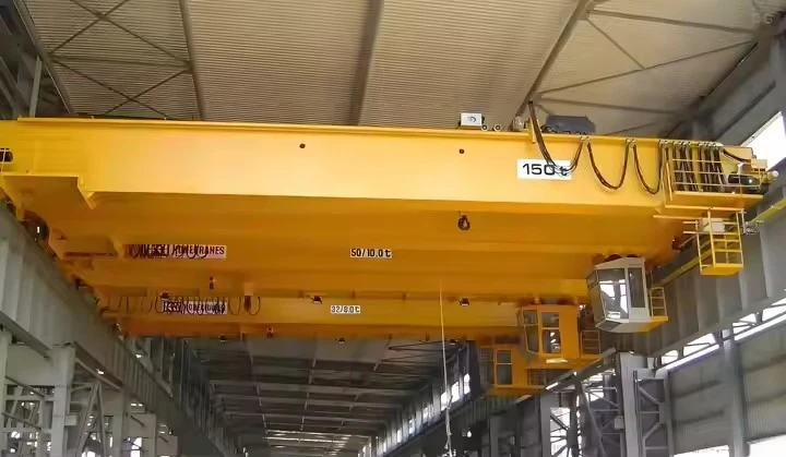


Qd Model Double Girder Bridge Overhead Cranes
Products Description
What is a QD Model Double Girder Bridge Crane?
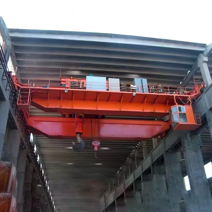
The "QD" designation is a model classification originally from the Chinese crane industry, with "Q" standing for "Bridge Crane" (Qiao Shi Qi Zhong Ji) and "D" standing for "Double Girder" (Shuang Liang). These are robust, top-running overhead cranes designed for heavy-duty industrial applications where high capacity, long spans, and precise handling are required.
They are characterized by their two main girders that run the length of the bridge, providing superior strength and rigidity compared to single girder cranes.
Features and Advantages
High Capacity: Designed for heavy-duty service (Class D, E, or F) with standard capacities ranging from 5 tons to over 550 tons.
Long Spans: The double girder design offers exceptional rigidity, allowing for much longer bridge spans (over 30 meters/100 feet) without excessive deflection (sagging).
Higher Hook Height: The trolley runs on top of the girders, maximizing the available lifting height under the crane structure compared to under-running (single girder) cranes.
Durability and Rigidity: The box girder construction provides excellent resistance to twisting and bending, ensuring smooth and precise load control.
Versatility: Can be equipped with various hoists, magnets, grabs, or other below-the-hook devices for specific materials (steel, lumber, bulk goods).
Customization: While a standard model, QD cranes are highly customizable in terms of span, lift height, speed, and control options.
QD vs. Other Common Standards
It's helpful to understand how QD compares to other common designations:
| Feature | QD Model (China Standard) | FEM / DIN (European Standard) | CMAA (American Standard - Class D) |
|---|---|---|---|
| Design Philosophy | Robust, cost-effective, widely available | Precision engineering, high-duty cycles | Heavy-duty, industrial focus |
| Girder Type | Predominantly fabricated box girder | Box girder or truss girder | Box girder or modified girder designs |
| Hoist Type | Often uses standardized "QD" modular hoists | Often uses integrated or European-style hoists | Often uses US-manufactured hoists (e.g., CM Lodestar) |
| Control | Pendant is very common; radio remote is an option | Radio remote and cab are very common | All options common; often tailored to application |
| Availability | Very common globally due to competitive pricing | Common in European projects and high-spec facilities | Common in North America and US-led projects |
Core Components:Bearing, Gearbox, Motor, Pump
Place of Origin:Henan, China
Warranty:1 Year
Weight (KG):2000 kg
Video outgoing-inspection:Provided
Machinery Test Report:Provided
Design:Double beam
Effectiveness:high efficiency
Operating speed:High speed operation
Stability:Anti-swing function
Color:Optional
Power Source:110V/220V/230V/380V/440V,customized
Span:7.5-31.5m

Pictures & Components
Of course. Here is a detailed breakdown of the components of a QD Model Double Girder Bridge Overhead Crane, organized by the main structural and functional systems.
This builds on the previous overview to give you a clear, part-by-part understanding.
1. Bridge Structure (The Main Moving Frame)
This is the primary structure that travels the length of the building (along the runway).
Main Girders (2): The two primary, horizontal load-bearing beams that run parallel to the runway. In QD models, these are almost always welded box girders, known for their high strength and rigidity, which minimizes deflection (sagging) under heavy loads.

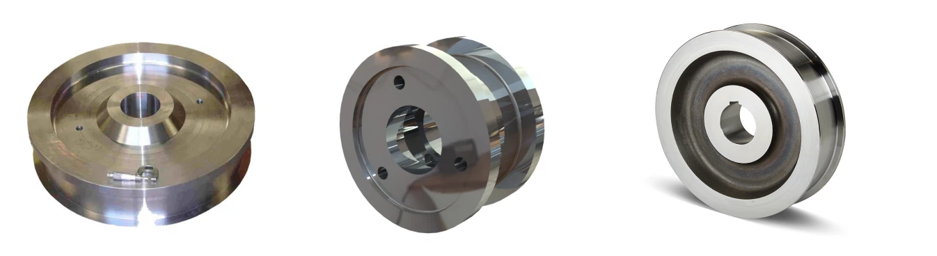
End Trucks (2): The sturdy assemblies at each end of the bridge that connect to the main girders. Each end truck houses:
Wheels: Typically two or more double-flanged wheels that ride on the runway rails.
Axles & Bearings: To support the wheels.
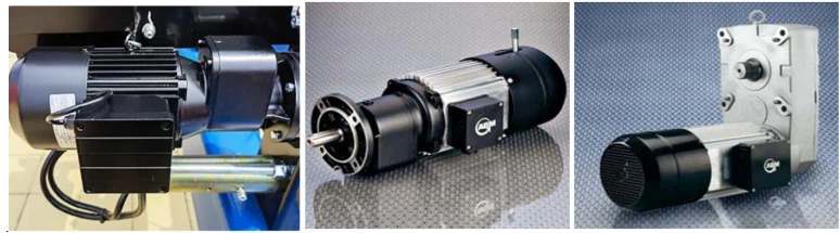
Drive Motor(s): One or more motors to propel the entire bridge along the runway (long travel motion).
Reduction Gearboxes: To reduce the motor's high speed to the required wheel torque.
Brakes: Usually an automatic fail-safe brake on the drive motor.
 |
 |
2. Trolley and Hoisting Unit
This unit moves across the width of the bridge (on top of the main girders) and performs the actual lifting.
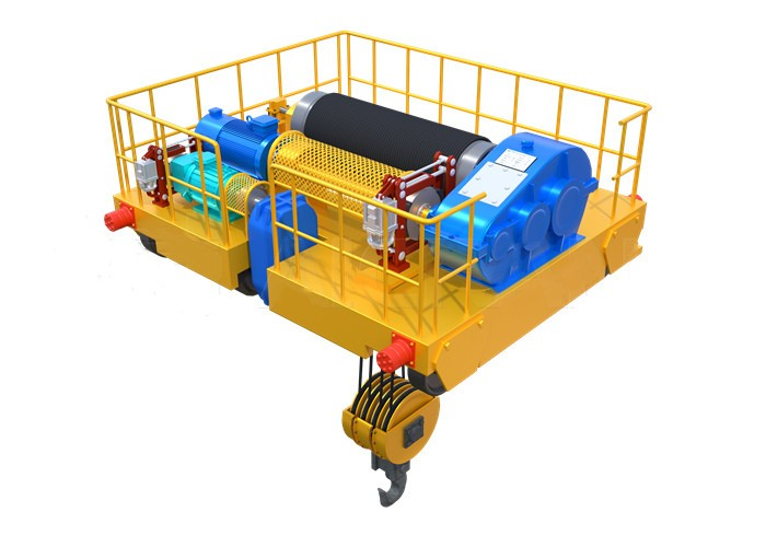
Trolley Frame: The rigid frame that carries the hoist and moves along rails mounted on the top of the main girders.
Trolley Drive: Consists of a motor, gearbox, brakes, and wheels that propel the trolley back and forth (cross travel motion).
 |
 |
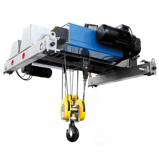
Hoist Unit: The core lifting device. On a QD crane, this is typically a standardized QD-type electric wire rope hoist, which itself consists of:
Hoist Motor: Powers the lifting and lowering.
Drum: The cylindrical assembly around which the wire rope is wound.
Wire Rope: The high-strength cable that does the lifting.
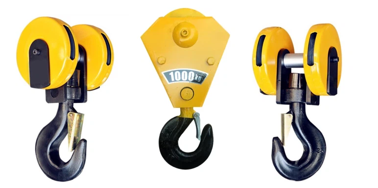
Hook Block: The assembly at the end of the rope, containing the hook, sheaves (pulleys), and often the load limiter.
Gearbox: Reduces the motor's speed to the desired lifting speed.
Brakes: Multiple brakes (usually a primary mechanical brake and an emergency load brake) for safe operation.
Cooling System: Many QD hoists are force-cooled with an independent fan motor to handle heavy-duty cycles without overheating.
3. Runway System (The Fixed Support Structure)
This is the stationary infrastructure installed on the building structure.
Runway Beams: Typically heavy-duty wide-flange (I-beams) or custom-fabricated box beams that are securely attached to the building's columns or freestanding support columns.
Runway Rails: Precision steel rails (e.g., ASCE, KRUPP, or DIN standards) that are bolted or welded onto the runway beams. The crane's end truck wheels travel on these rails.
Rail Clips / Fasteners: Secure the rail to the runway beam.
End Stops / Buffers: Physical barriers at the extreme ends of the runway to prevent the crane from over-traveling and derailing.
4. Electrical System and Controls
The nervous system of the crane, providing power and command.
Main Power Supply: Delivered via:
Festoon System: A cable-carrier system with a flexible ribbon cable that curls and uncurls as the crane moves.
Conductor Bar (Enclosed Raceway): A series of insulated bars mounted along the runway. Collectors on the crane slide along these bars to draw power. Better for long distances and heavy currents.
Control System:
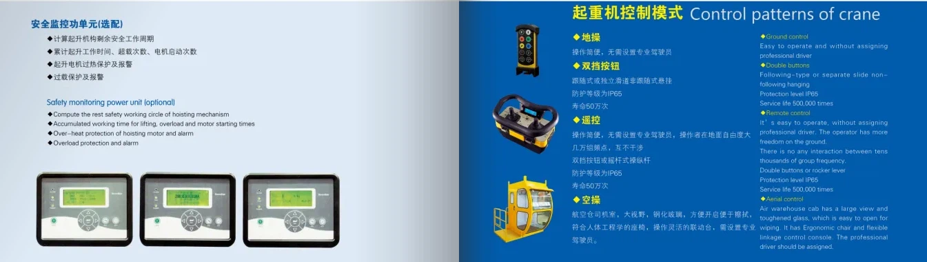
Pendant Control Station: A hanging, push-button box (pendant) that the operator uses to control all crane functions. It is connected via a festoon or a flexible cable that moves with the trolley.
Radio Remote Control: A wireless transmitter that allows the operator to control the crane from the floor with complete freedom of movement and optimal visibility. This is an extremely popular and safe option.
Cab Control: An operator's cab mounted on the bridge or trolley, containing all control levers/buttons.

Control Panel / Panel Box: Contains the contactors, overload relays, variable frequency drives (VFDs - for smooth speed control), transformers, and programmable logic controller (PLC) that manage power and logic for all motors.
Limit Switches: Critical safety sensors that cut power at the limits of travel.
Main Hoist Upper Limit Switch: Prevents overwinding and "two-blocking".
End Travel Limit Switches: For both bridge and trolley travel, to prevent collisions with the end stops.

5. Safety Devices (Integrated Throughout)
Load Limiter / Overload Limit Device: A critical sensor (often mechanical or electronic) that prevents the hoist from lifting a load beyond the crane's rated capacity (typically 110% of capacity).
Emergency Stop (E-Stop): Mushroom-head buttons on the pendant and often at ground level to cut all power to the crane motors immediately.
Anemometer & Anti-Wind System: For cranes installed outdoors, this measures wind speed and can lock the crane's motion if winds become dangerous.
Warning Devices: Rotating beacon lights and audible alarms (horns/buzzers) to alert personnel before the crane moves.
Sketch

Main technical

Advantages
Advantages of QD Double Girder Bridge Cranes
QD double girder cranes are engineered for performance and durability in demanding environments. Their advantages stem from their robust design and standardization.
1. High Load Capacity and Heavy-Duty Performance
Core Advantage: Their primary strength is the ability to handle very heavy loads, typically from 5 tons up to 550 tons or more.
Why: The double girder box design provides immense structural integrity and resistance to bending and twisting, making them ideal for Class D (Heavy-Duty), E (Severe-Duty), and F (Continuous Severe-Duty) service cycles.
2. Long Span Capability
Core Advantage: They can operate efficiently over long spans (over 30 meters/100 feet) between the runway rails.
Why: The two girders significantly reduce bridge deflection (sagging) compared to a single girder design. This ensures smooth and stable operation even when moving heavy loads across a wide bay.
3. Maximum Hook Height and Clearance
Core Advantage: The top-running trolley design provides superior hook height.
Why: Since the trolley runs on top of the girders, no crane structure is below the girders. This utilizes the full available building height, allowing loads to be lifted higher, which is critical in facilities with limited headroom.
4. Exceptional Durability and Rigidity
Core Advantage: The welded box girder construction offers superior rigidity and longevity.
Why: The closed-box design is highly resistant to torsional stress (twisting) and vertical deflection. This results in smoother travel, less sway on the load, and a longer service life, even in harsh industrial environments.
5. Versatility and Customization
Core Advantage: They can be equipped with a wide range of below-the-hook devices and customized to specific needs.
Why: The strong structure can support auxiliary hoists (for lighter loads), magnet systems for steel, grabs for bulk materials, rotators, vacuum lifters, and other specialized tools. Span, lift, speed, and control can all be tailored.
6. Improved Trolley Performance
Core Advantage: The trolley runs on a wide, stable rail on top of the girder, allowing for higher travel speeds and more precise load positioning.
Why: The design can support more powerful trolley drive motors and provides better traction and alignment than underhung trolleys.
7. Safety and Reliability
Core Advantage: Designed and built to international safety standards (like ISO, FEM).
Why: They integrate critical safety features as standard, including overload limit devices, emergency stops, limit switches for all movements, and secure braking systems. Their inherent stability minimizes risks associated with load sway.
8. Cost-Effectiveness for Heavy Lifting
Core Advantage: While the initial investment is higher than a single girder crane, they offer a lower total cost of ownership for heavy-duty applications.
Why: Their durability reduces maintenance costs and downtime. Their efficiency and reliability improve workflow productivity, handling jobs that would otherwise require multiple pieces of equipment.
Application:
Applications of QD Double Girder Bridge Cranes
These cranes are the workhorses of heavy industry. You will find them anywhere robust, reliable, and powerful lifting is required.
| Industry / Sector | Specific Application | Why a QD Crane is the Right Choice |
|---|---|---|
| Steel & Metal | Steel mills, fabrication shops, foundries. Handling coils, sheets, plates, raw billets, and finished structures. | High capacity needed for heavy weights. Durability to withstand molten heat and harsh conditions. Often used with electromagnets or C-hooks. |
| Power Generation | Hydro, nuclear, and thermal power plants. Installing/maintaining turbines, generators, rotors, and transformers. | Extreme precision and very high capacities (often 100+ tons) required for critical, valuable components. |
| Paper & Pulp | Paper mills. Handling massive, heavy rolls of paper. | Precise positioning is needed to avoid damaging rolls. Variant: Can be equipped with specialized paper roll hooks. |
| Heavy Machinery | Manufacturing plants for construction, mining, and agricultural equipment. Moving large frames, booms, and assemblies. | Long spans to cover large assembly bays. Rigidity for precise placement of large, awkward components. |
| Aerospace | Manufacturing and maintenance hangars. Lifting fuselages, wings, and engines. | Clean, precise control (often with VFDs) to handle incredibly valuable and delicate structures without shock loads. |
| Shipbuilding & Ports | Dry docks and warehouses. Moving large ship sections, engines, and containers. | Outdoor models available with anti-wind systems. High capacity to lift massive loads. |
| Automotive | Stamping plants. Moving large metal dies in and out of stamping presses. | Reliability and durability for constant, heavy cycling. High hook approach to reach into presses. |
| Heavy Logistics | Large warehouses and rail depots. Moving heavy machinery, transformers, and industrial products. | Covers a large area (long span) and provides a flexible, robust lifting solution for diverse heavy loads. |
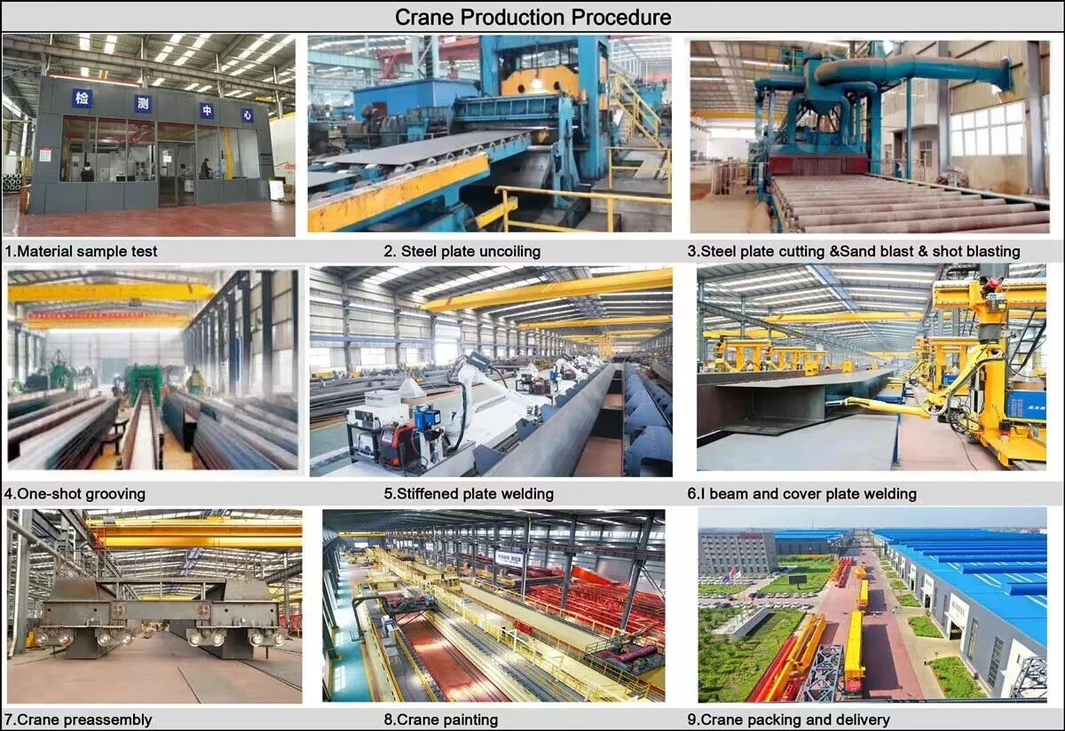
Crane production procedure
The production of a QD Model Double Girder Bridge Overhead Crane is a meticulous process that blends heavy steel fabrication, precise machining, electrical assembly, and rigorous quality control.
Stage 1: Design & Engineering (Pre-Production)
Order Review & Technical Clarification: Engineers review the customer's specifications (capacity, span, lift height, duty class, control mode, etc.).
Detailed Design & Calculation:
Structural Design: Using CAD software (e.g., AutoCAD, SolidWorks), engineers create detailed drawings for every component (girders, end trucks, trolley frame). The girder design is critically analyzed for deflection, strength, and fatigue life.
Electrical Design: Schematics for the power and control systems are developed, including the bill of materials for motors, panels, cables, and pendants.
Load Calculation & FEM Analysis: Modern factories use Finite Element Method (FEM) software to simulate stress, strain, and deflection under load, optimizing the design before any metal is cut.
Stage 2: Raw Material Preparation & Processing
Material Procurement: Steel plates (typically Q235B or Q345B for main structures), profiles (beams, channels), rails, and purchased parts (motors, gearboxes, wheels, electrical components) are sourced from certified suppliers.
Material Testing: Incoming steel plates are often tested for conformity to grade specifications (ultrasonic testing is common).
Cutting & Forming:
CNC Cutting: Steel plates for the main girders are cut to precise dimensions using Computer Numerical Control (CNC) plasma or flame cutting machines. This ensures high accuracy.
Drilling & Machining: Holes for connections are drilled using magnetic base drills or CNC machining centers. The ends of the main girders are machined to ensure a perfect, square fit with the end trucks.
Stage 3: Main Girder Fabrication (The Core Process)
This is the most critical welding process.
Assembly & Jigging: The cut plates (web and flange) are placed in a large, rigid assembly jig. This jig holds everything in perfect alignment during welding to prevent distortion and ensure the girder is straight and cambered correctly.
Welding: Main girder welding is performed by certified welders using Submerged Arc Welding (SAW) for long, main seams (which provides deep penetration and high-quality welds) and Manual Metal Arc Welding (MMA) or Gas Metal Arc Welding (GMAW/MIG) for smaller attachments.
Cambering: A pre-defined upward camber (curvature) is built into the girder to counteract deflection under the load's weight. This is achieved by the jig design and welding sequence.
NDT (Non-Destructive Testing): Critical welds are inspected by quality inspectors. Methods include:
Ulasonic Testing (UT): For detecting internal flaws in welds.
Magnetic Particle Testing (MT): For detecting surface cracks.
Fitting Attachment: After welding, the rails for the trolley are meticulously aligned and welded or bolted onto the top of the finished girders.
Stage 4: End Truck & Trolley Frame Fabrication
Fabrication: The end truck housings and trolley frame are fabricated from steel plate, following similar processes of cutting, drilling, and welding.
Machining: Key areas, such as the bearing housings for the wheels and the drive shafts, are machined to high tolerances to ensure perfect alignment and smooth operation.
Assembly: Wheels, bearings, axles, drive motors, and gearboxes are assembled onto the end trucks. The same is done for the trolley frame.
Stage 5: Surface Treatment & Painting
Shot Blasting: All structural components are fed into a shot blasting machine where high-speed steel abrasives clean the surface of rust, mill scale, and dirt. This creates a rough, clean surface ideal for paint adhesion.
Priming: Immediately after blasting, a high-quality anti-rust primer is applied to prevent oxidation.
Painting: The topcoat is applied, usually according to customer-specified color and thickness requirements. This is often done using spray painting for an even finish.
Stage 6: General Assembly & Electrical Installation
Pre-Assembly: The main girders are connected to the end trucks to form the complete bridge. The trolley is placed on the bridge rails. The entire structure is checked for squareness and dimensional accuracy.
Mechanical Installation: The hoist unit (QD-type hoist) is installed onto the trolley frame. All drives are connected.
Electrical Installation: Electricians wire the entire crane:
Install the main panel and resistance box on the bridge.
Run cables along the bridge to the trolley and end truck drives.
Install the festoon system or conductor bar for power collection.
Install limit switches, safety devices, and warning lights.
Connect the control pendant or test the radio remote control.
Stage 7: Testing & Inspection (Factory Acceptance Test - FAT)
This is a mandatory step before dismantling for shipment.
No-Load Test: The crane is operated without a load. All functions are tested: bridge travel, trolley travel, hoisting up and down. Limits, brakes, and controls are checked.
Static Load Test: A test load of 125% of the rated capacity is lifted just off the ground (typically with test weights or calibrated water bags). The crane is held for 10+ minutes to check for any deformation, and the brakes are checked for holding ability.
Dynamic Load Test: A test load of 110% of the rated capacity is lifted and put through all motions: traveling, trolleying, and hoisting. This tests the functionality and safety under stress.
Dimensional Inspection: Key dimensions (span, lift height, etc.) are verified against the order.
Documentation: All test results, certificates for materials and welds, and equipment manuals are compiled into a final delivery dossier for the customer.
Stage 8: Dismantling, Packaging & Shipping
Dismantling: The crane is carefully disassembled into logical, shippable components (e.g., two main girders, two end trucks, trolley unit, hoist, electrical panels, runway rails).
Packaging: Components are packaged to prevent damage during sea or land transport. Structural parts are often bundled on wooden crates. Electrical components are boxed and stored in wooden cases.
Shipping: All parts are marked for easy identification and site reassembly. They are then shipped to the customer's site for installation by the manufacturer's technicians or the customer's own team.
Workshop view:
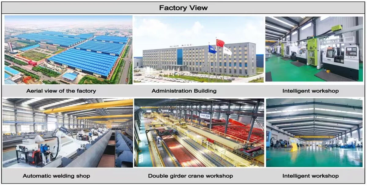
The company has installed an intelligent equipment management platform, and has installed 310 sets (sets) of handling and welding robots. After the completion of the plan, there will be more than 500 sets (sets), and the equipment networking rate will reach 95%. 32 welding lines have been put into use, 50 are planned to be installed, and the automation rate of the entire product line has reached 85%.


Hot Tags: qd model double girder bridge overhead cranes, China qd model double girder bridge overhead cranes manufacturers, suppliers, factory, Double Girder Overhead Crane, Double Girder Overhead Travelling Crane
You Might Also Like


Send Inquiry