










180T Bridge Launching Girder
A 180T Bridge Launching Girder is a specialized construction machine designed for lifting, transporting, and erecting precast concrete bridge girders weighing up to 180 tons. It is widely used in highway, railway, and urban viaduct bridge projects where heavy concrete beams must be installed efficiently and safely.

Product Features
Features of 180T Bridge Launching Girder
1. Heavy-Duty Lifting Capacity
Designed to lift and erect precast concrete girders up to 180 tons.
Suitable for large highway, railway, and metro bridge projects.
2. Modular Steel Structure
High-strength steel truss or box-girder design.
Modular sections facilitate transportation, assembly, and maintenance.
3. Dual Trolley Lifting System
Equipped with front and rear lifting trolleys.
Ensures synchronized lifting and stable beam handling.
4. Longitudinal Launching Capability
Can move forward span by span along the completed bridge deck.
Reduces the need for large ground-based cranes.
5. Precise Beam Positioning
Hydraulic and PLC-controlled systems provide accurate alignment and placement of girders.
Minimizes installation errors.
6. Multi-Function Operation
Capable of beam lifting, transportation, launching, and erection using a single machine.
Improves construction efficiency.
7. Advanced Hydraulic System
Hydraulic cylinders control support legs, steering mechanisms, and beam positioning.
Ensures smooth and reliable operation.
8. Intelligent Control System
PLC-based electrical controls with real-time monitoring.
Remote and cabin control options available.
9. Adaptability to Various Bridge Types
Suitable for:
Precast box girders
T-girders
I-girders
U-girders
Can be customized for straight, curved, or inclined bridges.
10. High Safety Standards
Overload protection system.
Wind speed monitoring device.
Travel and lifting limit switches.
Emergency stop functions.
Anti-collision protection.
11. Stable Support System
Front, middle, and rear support legs distribute loads effectively.
Provides excellent stability during launching and erection operations.
12. Efficient Construction Performance
Enables rapid bridge girder installation.
Reduces labor costs and project duration.
Suitable for continuous span erection operations.
13. All-Weather Operation
Designed for operation in challenging construction environments.
Reliable performance under varying weather and site conditions.
14. Low Maintenance Requirements
Durable components and robust construction.
Easy access to key mechanical and electrical systems for servicing.
15. Customizable Design
Span length, lifting height, beam type, power supply, and control system can be tailored to specific project requirements.
Key Design Parameters & Performance Specifications
| Parameter | Specification |
|---|---|
| Lifting Capacity (per girder) | 180 Metric Tons |
| Maximum Span (Pier to Pier) | 50 meters (Typical), customizable up to 60m |
| Minimum Curve Radius | 2,000 meters (can be designed for tighter radii) |
| Maximum Supported Grade | ±4% |
| Lifting Hoists | 2 x Main Hoists (typically 120-ton capacity each) |
| Hoist Lifting Speed | 0-5 m/min (variable speed control) |
| Trolley Traversing Speed | 0-10 m/min (variable speed control) |
| Main Beam Launching Speed | 0-5 m/min (variable speed control) |
| Machine Self-Propelling Speed | 0-5 m/min (variable speed control) |
| Control System | Centralized PLC with frequency control for all motions. Remote control operation. |
| Power Supply | 380V / 50Hz / 3 Phase (or as per project requirement) |

Pictures & Components
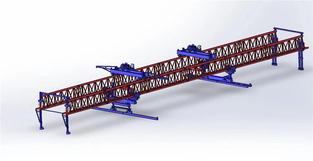
Components of 180T Bridge Launching Girder
1. Main Girder
The primary load-bearing structure of the launching girder.
Manufactured from high-strength steel in truss or box-girder form.
Supports lifting trolleys and transfers loads during beam erection.
2. Front Support Leg
Positioned on the bridge pier or completed span ahead.
Provides stability and support during launching operations.
Equipped with hydraulic adjustment mechanisms.
3. Middle Support Leg
Located near the center of the machine.
Carries a significant portion of the working load.
Ensures balanced load distribution during girder erection.
4. Rear Support Leg
Installed on the completed bridge deck.
Supports the rear section of the launching girder.
Assists in longitudinal movement and launching.
5. Front Lifting Trolley
Travels along the main girder.
Responsible for lifting and transporting the front end of the precast girder.
Equipped with hoists, motors, and safety devices.
6. Rear Lifting Trolley
Works synchronously with the front trolley.
Handles the rear end of the concrete girder.
Ensures smooth and stable beam transportation.
7. Hoisting System
Includes electric winches, wire ropes, drums, pulleys, and hooks.
Provides the lifting force required for girder handling and installation.
8. Longitudinal Traveling Mechanism
Enables the launching girder to move forward from one span to the next.
Consists of drive motors, wheel assemblies, reducers, and rail systems.
9. Transverse Traveling Mechanism
Allows lateral movement of lifting trolleys and girders.
Facilitates accurate beam positioning on bridge bearings.
10. Hydraulic System
Composed of hydraulic cylinders, pumps, valves, pipelines, and oil tanks.
Controls support leg lifting, steering, and positioning functions.
11. Electrical Control System
PLC-based control cabinet.
Coordinates lifting, traveling, and launching operations.
Features monitoring, diagnostics, and safety interlocks.
12. Power Supply System
Provides electrical power to motors, winches, hydraulic units, and control systems.
Can be configured according to project power requirements.
13. Safety Protection System
Overload limiters.
Travel limit switches.
Emergency stop devices.
Wind speed monitoring system.
Anti-collision protection devices.
14. Cable Management System
Includes cable reels, festoon systems, and cable trays.
Ensures safe and reliable power and signal transmission.
15. Operator Cabin (Optional)
Provides centralized control and monitoring of machine operations.
Equipped with control panels, displays, and communication systems.

Sketch

Advantages
Advantages of 180T Bridge Launching Girder
1. High Lifting Capacity
Designed to handle precast concrete girders weighing up to 180 tons.
Suitable for large-scale highway, railway, and urban bridge construction projects.
2. Improved Construction Efficiency
Integrates girder lifting, transportation, positioning, and erection into one system.
Enables rapid span-by-span bridge construction, significantly reducing project duration.
3. Reduced Dependence on Ground Cranes
Performs beam erection directly on bridge piers and completed spans.
Ideal for locations where large mobile cranes cannot access the site.
4. Excellent Operational Stability
Multi-support leg structure ensures balanced load distribution.
Provides stable operation during lifting, launching, and girder placement.
5. Precise Beam Placement
Equipped with hydraulic positioning and synchronized lifting systems.
Ensures accurate alignment of girders on bridge bearings.
6. Enhanced Safety Performance
Features overload protection, emergency stop devices, travel limit switches, and anti-collision systems.
Minimizes operational risks and improves workplace safety.
7. Adaptability to Various Bridge Designs
Suitable for:
Box girders
T-girders
I-girders
U-girders
Can be customized for straight, curved, skewed, and inclined bridge alignments.
8. Lower Labor Requirements
Automated control systems reduce manual intervention.
Fewer personnel are required compared with conventional erection methods.
9. Cost-Effective Solution
Reduces equipment rental costs and construction time.
Improves overall project productivity and return on investment.
10. Suitable for Difficult Terrain
Performs efficiently over rivers, valleys, highways, railways, and mountainous regions.
Eliminates many site access limitations faced by traditional lifting equipment.
11. Intelligent Control System
PLC-based controls provide real-time monitoring and synchronized operations.
Enhances accuracy, reliability, and operational efficiency.
12. Reliable Structural Strength
Manufactured from high-strength steel with advanced welding technology.
Designed for long service life and heavy-duty operation.
13. Flexible Span Erection
Can launch itself forward from one span to the next after beam installation.
Supports continuous bridge construction without frequent dismantling.
14. Low Maintenance Requirements
Durable components and modular design simplify inspection and servicing.
Reduces maintenance downtime and operating costs.
15. Environmental Benefits
Minimizes disturbance to the ground and surrounding environment.
Reduces the need for temporary access roads and large lifting platforms.
Summary
The 180T Bridge Launching Girder offers a combination of high lifting capacity, superior safety, precise positioning, operational efficiency, and adaptability, making it an ideal solution for modern bridge construction projects involving heavy precast concrete girders.

Application
Applications of 180T Bridge Launching Girder
1. Highway Bridge Construction
Erection of precast concrete box girders for expressways and highways.
Installation of T-beams and I-beams for multi-span bridge projects.
Suitable for large-scale transportation infrastructure developments.
2. Railway Bridge Projects
Construction of conventional railway bridges.
Installation of heavy precast girders for freight railway lines.
Suitable for long-span and high-load railway bridge structures.
3. High-Speed Railway Viaducts
Efficient erection of precast box girders for high-speed rail networks.
Ensures precise beam placement and alignment required for high-speed train operations.
4. Urban Metro and Light Rail Systems
Construction of elevated metro lines and light rail viaducts.
Ideal for projects in densely populated urban areas where ground crane access is limited.
5. Elevated Expressways
Installation of heavy concrete girders for urban elevated highways.
Supports rapid construction with minimal disruption to existing traffic.
6. Interchange and Flyover Bridges
Used for complex bridge structures at highway interchanges.
Enables safe and efficient girder erection in restricted construction zones.
7. River Crossing Bridges
Suitable for erecting girders over rivers, lakes, and reservoirs.
Eliminates the need for large floating cranes or temporary support structures.
8. Valley and Mountain Bridge Construction
Ideal for projects in mountainous and difficult-to-access terrain.
Allows girder erection where conventional lifting equipment cannot operate effectively.
9. Coastal and Marine Bridge Projects
Used in bridge construction across coastal regions and estuaries.
Provides stable operation in challenging environmental conditions.
10. Municipal Infrastructure Projects
Construction of urban overpasses, ring roads, and transportation corridors.
Supports large-scale public infrastructure development.
11. Precast Segmental Bridge Construction
Handles heavy precast bridge segments and girders.
Ensures accurate placement for segmental bridge assembly.
12. Long-Span Bridge Erection
Suitable for medium and long-span precast concrete bridge projects.
Supports continuous span-by-span launching and installation operations.

Production Procedure
Production Procedure of 180T Bridge Launching Girder
1. Engineering Design
Project requirement analysis.
Structural strength and stability calculations.
3D modeling and finite element analysis (FEA).
Preparation of fabrication drawings and technical documents.
2. Raw Material Procurement
Selection of high-quality structural steel plates and sections.
Procurement of motors, reducers, hydraulic components, electrical systems, and wire ropes.
Verification of material certificates and specifications.
3. Material Inspection
Chemical composition and mechanical property testing.
Dimensional inspection of steel materials.
Quality verification according to manufacturing standards.
4. CNC Cutting
CNC plasma or flame cutting of steel plates.
Cutting of webs, flanges, stiffeners, and connection plates.
Edge preparation for welding operations.
5. Component Fabrication
Main Girder Manufacturing
Assembly of truss or box-girder sections.
Installation of diaphragms and reinforcing plates.
Dimensional alignment and inspection.
Support Leg Fabrication
Manufacturing of front, middle, and rear support legs.
Assembly of support frames and hydraulic mounting points.
Trolley Frame Fabrication
Fabrication of lifting trolley structures.
Installation of wheel assemblies and drive components.
6. Welding Process
CO₂ gas shielded welding.
Submerged arc welding (SAW) for major structural joints.
Welding according to approved procedures and standards.
Continuous quality monitoring during fabrication.
7. Non-Destructive Testing (NDT)
Ultrasonic Testing (UT).
Magnetic Particle Testing (MT).
Dye Penetrant Testing (PT) where required.
Inspection of critical weld seams and load-bearing components.
8. Machining and Finishing
Machining of shafts, wheel sets, bearing housings, and pins.
Drilling and boring of connection holes.
Precision finishing of mechanical components.
9. Pre-Assembly
Trial assembly of main structural sections.
Verification of dimensions and connection accuracy.
Adjustment of alignment and tolerances.
10. Surface Treatment
Shot blasting to remove rust, scale, and contaminants.
Surface cleaning to achieve specified preparation standards.
Inspection of surface quality before painting.
11. Painting and Corrosion Protection
Application of epoxy zinc-rich primer.
Intermediate protective coating.
Polyurethane or customized topcoat finish.
Dry film thickness inspection.
12. Mechanical Assembly
Installation of:
Hoisting winches
Motors and reducers
Wheel assemblies
Wire ropes and pulley blocks
Traveling mechanisms
13. Hydraulic System Installation
Installation of hydraulic cylinders.
Mounting of pumps, valves, oil tanks, and pipelines.
Hydraulic pressure and leakage testing.
14. Electrical System Installation
PLC control cabinet assembly.
Wiring of motors, sensors, and limit switches.
Installation of remote-control and monitoring systems.
Electrical insulation testing.
15. Complete Machine Assembly
Integration of all structural, mechanical, hydraulic, and electrical components.
Functional system verification.
Alignment and calibration.
16. Factory Testing
No-Load Test
Verification of all movements and controls.
Inspection of electrical and hydraulic systems.
Load Test
Static load testing.
Dynamic load testing.
Verification of lifting, traveling, and launching functions.
Safety Test
Overload protection verification.
Emergency stop testing.
Limit switch and safety interlock inspection.
17. Final Quality Inspection
Dimensional inspection.
Performance verification.
Review of welding, painting, and assembly quality.
Preparation of quality records and certificates.
18. Packaging and Delivery
Disassembly into transportable modules.
Protective packing of electrical and hydraulic components.
Container or truck loading.
Shipment to the project site.


Workshop View
The company has installed an intelligent equipment management platform, and has installed 310 sets (sets) of handling and welding robots. After the completion of the plan, there will be more than 500 sets (sets), and the equipment networking rate will reach 95%. 32 welding lines have been put into use, 50 are planned to be installed, and the automation rate of the entire product line has reached 85%.


Hot Tags: 180t bridge launching girder, China 180t bridge launching girder manufacturers, suppliers, factory
You Might Also Like


Send Inquiry