







170T Beam Launcher Machine For Erecting Concrete Girders manufacturers

170T Beam Launcher Machine For Erecting Concrete Girders suppliers

170T Beam Launcher Machine For Erecting Concrete Girders factory

170T Beam Launcher Machine For Erecting Concrete Girders best

170T Beam Launcher Machine For Erecting Concrete Girders high quality
170T Beam Launcher Machine For Erecting Concrete Girders
A 170T Beam Launcher Machine is a specialized bridge construction equipment designed for the lifting, transportation, positioning, and erection of precast concrete girders in highway, railway, metro, and viaduct projects. It is commonly used for installing T-girders, I-girders, U-girders, and box girders with high precision and safety across bridge spans. Modern beam launchers feature self-advancing mechanisms, hydraulic support systems, and intelligent control systems to improve erection efficiency and reduce labor requirements.

Product Features
Rated lifting capacity of 170 tons for heavy concrete girder erection.
Suitable for bridge spans typically ranging from 30m to 50m.
Self-launching design eliminates the need for large ground-based cranes.
High-strength truss or box-girder structure with excellent rigidity and wind resistance.
Hydraulic lifting and traveling systems for smooth operation.
Adjustable support legs for straight, curved, and inclined bridges.
Frequency-controlled lifting and traveling mechanisms for precise positioning.
Modular structure for convenient transportation and site assembly.
Integrated safety monitoring, overload protection, and emergency stop systems.
Capable of beam feeding from the rear deck, side, or ground level depending on project requirements.
Key Design Parameters & Performance Specifications
| Parameter | Specification |
|---|---|
| Lifting Capacity (per girder) | 170 Metric Tons |
| Maximum Span (Pier to Pier) | 50 meters (Typical), customizable up to 60m |
| Minimum Curve Radius | 2,000 meters (can be designed for tighter radii) |
| Maximum Supported Grade | ±4% |
| Lifting Hoists | 2 x Main Hoists (typically 120-ton capacity each) |
| Hoist Lifting Speed | 0-5 m/min (variable speed control) |
| Trolley Traversing Speed | 0-10 m/min (variable speed control) |
| Main Beam Launching Speed | 0-5 m/min (variable speed control) |
| Machine Self-Propelling Speed | 0-5 m/min (variable speed control) |
| Control System | Centralized PLC with frequency control for all motions. Remote control operation. |
| Power Supply | 380V / 50Hz / 3 Phase (or as per project requirement) |

Pictures & Components
The main components of a 170T Beam Launcher Machine include:
1. Main Girder (Launching Truss)
Primary load-bearing structure of the launcher.
Supports the lifting trolleys and concrete girder during transportation and erection.
Typically fabricated from high-strength welded steel truss or box-girder sections.
2. Front Support Leg
Supports the front end of the launcher on the bridge pier.
Transfers vertical and horizontal loads during launching and girder erection.
Equipped with hydraulic adjustment mechanisms.
3. Middle Support Leg
Provides stability and load distribution during operation.
Assists in the self-launching process when moving to the next span.
4. Rear Support Leg
Supports the rear section of the launcher.
Maintains structural balance during beam transportation and erection.
5. Front Lifting Trolley
Travels along the main girder.
Lifts and carries the front end of the concrete girder.
Equipped with hoisting winches, motors, and braking systems.
6. Rear Lifting Trolley
Lifts and supports the rear end of the girder.
Coordinates with the front trolley for synchronized lifting and movement.
7. Hoisting Mechanism
Includes motors, reducers, drums, wire ropes, hooks, and pulleys.
Responsible for lifting and lowering the concrete girder safely.
8. Longitudinal Traveling Mechanism
Enables movement of the lifting trolleys along the launcher.
Used for transporting girders to the erection position.
9. Transverse Traveling Mechanism
Allows lateral adjustment of the girder.
Ensures accurate alignment with bridge bearings.
10. Hydraulic System
Provides power for support leg adjustment, launching operations, and auxiliary movements.
Includes hydraulic pumps, cylinders, valves, and pipelines.
11. Electrical Control System
Controls all machine operations.
Includes PLC, frequency inverters, control cabinets, sensors, and monitoring devices.
12. Power Supply System
Supplies electrical power to motors, controls, and hydraulic equipment.
May be powered by grid electricity or generator sets.
13. Beam Carrying Device
Supports and stabilizes the concrete girder during transportation and erection.
Includes lifting beams, spreader frames, and suspension assemblies.
14. Wire Rope and Pulley System
Transfers lifting forces from the hoisting mechanism to the girder.
Designed with high safety factors for heavy-duty operation.
15. Safety Protection System
Overload limiter.
Travel limit switches.
Wind-speed monitoring device.
Emergency stop system.
Anti-collision protection.
Rope breakage protection.
Real-time operation monitoring system.
16. Operator Cabin (Optional)
Provides centralized control and monitoring.
Equipped with displays, joysticks, alarms, and communication systems.
17. Maintenance Platforms and Walkways
Installed along the main girder.
Facilitate inspection, maintenance, and safe operator access

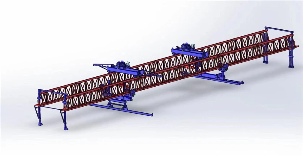
Sketch

Advantages
1. High Lifting Capacity
Designed to handle concrete girders up to 170 tons safely and efficiently.
Suitable for large highway, railway, and metro bridge projects.
2. High Construction Efficiency
Enables rapid span-by-span girder erection.
Reduces bridge construction time significantly compared with conventional crane methods.
Allows continuous operation with minimal interruption.
3. Self-Launching Capability
Can advance from one span to the next without the assistance of large external lifting equipment.
Minimizes site preparation requirements and equipment mobilization costs.
4. Reduced Construction Cost
Decreases dependence on large crawler cranes and temporary support structures.
Reduces labor requirements and overall project expenses.
5. Excellent Safety Performance
Equipped with overload protection, limit switches, emergency stop systems, and monitoring devices.
Provides stable lifting and precise girder positioning.
Reduces risks associated with heavy-load handling.
6. Precise Beam Positioning
Front and rear lifting trolleys operate synchronously for accurate girder placement.
Hydraulic adjustment systems ensure precise alignment with bridge bearings.
7. Adaptability to Various Bridge Types
Suitable for:
Straight bridges
Curved bridges
Skew bridges
Variable-span bridges
Elevated viaducts
8. Minimal Ground Occupation
Operates primarily on completed bridge structures.
Ideal for congested urban areas, rivers, valleys, highways, and environmentally sensitive locations.
9. Strong Structural Stability
High-strength steel truss or box-girder construction provides excellent rigidity and load-bearing performance.
Capable of operating under demanding site conditions.
10. Modular Design
Components can be easily transported, assembled, dismantled, and relocated.
Facilitates use on multiple projects.
11. Wide Project Applicability
Suitable for installing:
Precast T-girders
I-girders
Box girders
U-girders
Segmental bridge elements
12. Intelligent Control System
PLC and frequency-converter control provide smooth operation.
Real-time monitoring improves operational accuracy and reliability.
Supports remote control and automated safety diagnostics.
13. Reduced Environmental Impact
Less disturbance to traffic and surrounding areas.
Lower site footprint compared with large ground-based lifting equipment.
Suitable for projects with strict environmental requirements.
14. Improved Project Schedule Reliability
Consistent erection performance regardless of difficult terrain.
Reduces delays caused by limited crane access or restricted working space.
Summary
A 170T Beam Launcher Machine offers high lifting capacity, rapid erection speed, excellent safety, precise positioning, low operating costs, and strong adaptability, making it one of the most efficient solutions for installing heavy precast concrete girders in modern bridge construction projects.

Application
A 170T Beam Launcher Machine is widely used in the construction of bridges and elevated structures where heavy precast concrete girders need to be installed safely and efficiently.
1. Highway Bridge Construction
Erection of precast concrete T-girders, I-girders, and box girders.
Suitable for expressways, national highways, and elevated road projects.
Enables rapid span-by-span bridge construction.
2. Railway Bridge Construction
Installation of heavy concrete girders for conventional railway lines.
Provides accurate beam placement to meet strict railway alignment requirements.
3. High-Speed Railway Projects
Used for erecting large precast box girders on high-speed rail viaducts.
Ensures high precision and stability during installation.
4. Metro and Urban Transit Viaducts
Ideal for elevated metro systems and light rail transit projects.
Operates efficiently in densely populated urban environments with limited ground access.
5. Flyovers and Interchanges
Erection of girders for urban overpasses, flyovers, and multi-level interchanges.
Reduces disruption to existing traffic during construction.
6. Cross-River and Valley Bridges
Suitable for bridge projects over rivers, lakes, valleys, and other difficult terrains.
Eliminates the need for large cranes operating from the ground or water.
7. Curved and Skew Bridge Construction
Capable of handling girder installation on curved, skewed, and variable-width bridge alignments.
Provides precise positioning through hydraulic and trolley adjustment systems.
8. Long Viaduct Projects
Widely used in long-span elevated corridors where hundreds of girders must be erected continuously.
Increases construction productivity and consistency.
9. Infrastructure Development Projects
Expressway networks
Railway expansion projects
Urban transportation systems
Industrial transportation corridors
Port and logistics infrastructure

Production Procedure
The production of a 170T Beam Launcher Machine involves a series of engineering, fabrication, assembly, and testing processes to ensure structural reliability, lifting safety, and operational performance.
1. Engineering Design
Project requirement analysis
Structural strength and stability calculations
Finite Element Analysis (FEA)
Mechanical and hydraulic system design
Electrical control system design
Preparation of manufacturing drawings
2. Raw Material Procurement and Inspection
Procurement of high-quality steel plates and profiles
Inspection of material certificates
Chemical composition verification
Mechanical property testing
Dimensional inspection
3. CNC Cutting and Material Preparation
CNC flame cutting
Plasma cutting
Saw cutting of structural members
Edge preparation for welding
Material identification and marking
4. Main Structure Fabrication
Main Girder Manufacturing
Plate assembly
Web and flange alignment
Tack welding
Full welding according to WPS requirements
Support Leg Fabrication
Front support leg manufacturing
Middle support leg manufacturing
Rear support leg manufacturing
Auxiliary Structure Fabrication
Maintenance platforms
Walkways
Guardrails
Lifting brackets
5. Welding and Quality Inspection
CO₂ gas shielded welding
Submerged arc welding
Weld visual inspection
Ultrasonic Testing (UT)
Magnetic Particle Testing (MT)
Dimensional verification
6. Machining of Components
Wheel machining
Drum machining
Shaft machining
Bearing housing machining
Pulley processing
Reducer mounting surface machining
7. Surface Treatment
Shot blasting to Sa2.5 standard
Surface cleaning
Primer coating application
Intermediate paint application
Finish coating application
Dry film thickness inspection
8. Mechanical Assembly
Installation of lifting trolleys
Wheel assembly
Winch installation
Reducer installation
Coupling installation
Brake installation
9. Hydraulic System Installation
Hydraulic cylinder installation
Hydraulic pump assembly
Hydraulic valve block installation
Hydraulic piping connection
Pressure testing
Leakage inspection
10. Electrical System Installation
Control cabinet assembly
Motor installation
PLC programming
Frequency inverter installation
Cable laying
Sensor installation
Safety device integration
11. Factory Pre-Assembly
Main girder assembly
Support leg assembly
Trolley installation
Mechanical alignment inspection
Functional verification of all mechanisms
12. Testing and Commissioning
No-Load Testing
Hoisting operation test
Trolley traveling test
Launcher traveling test
Hydraulic system test
Electrical system test
Load Testing
Static load test
Dynamic load test
Safety device verification
Structural deformation measurement
13. Final Quality Inspection
Dimensional inspection
Weld quality inspection
Paint quality inspection
Electrical system verification
Documentation review
Compliance verification
14. Packing and Delivery
Component labeling
Protective packaging
Transportation securing
Shipping documentation preparation
Loading for transport
15. Site Installation and Commissioning
Site assembly of main structures
Mechanical and electrical connections
Hydraulic system commissioning
Alignment and calibration
Trial operation
Load testing on site
Operator training
Final acceptance


Workshop View
The company has installed an intelligent equipment management platform, and has installed 310 sets (sets) of handling and welding robots. After the completion of the plan, there will be more than 500 sets (sets), and the equipment networking rate will reach 95%. 32 welding lines have been put into use, 50 are planned to be installed, and the automation rate of the entire product line has reached 85%.


Hot Tags: 170t beam launcher machine for erecting concrete girders, China 170t beam launcher machine for erecting concrete girders manufacturers, suppliers, factory
You Might Also Like


Send Inquiry