


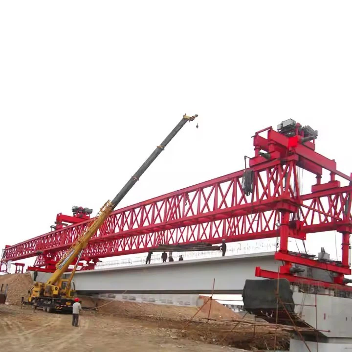


120 Tons Counterweight Bridge Lancher Machine
The "counterweight" is a key feature that balances the machine during the launching process, allowing it to reach further out from the bridge pier without toppling over. The "120-ton" typically refers to its lifting capacity per leg or per trolley, not its total weight (which is much higher).

Typical Construction Method (Incremental Launching or Segmental Erection):
Setup: The launcher is assembled on the bridge abutment or on falsework over the first few piers.
Segment Delivery: Pre-cast concrete segments (box girders, U-beams, etc.) are transported to the site and fed to the launcher from the rear, often on a transport vehicle.
Lifting & Placement: The launcher's trolleys pick up a segment (weighing up to 120 tons), move it forward, and precisely position it against the previously placed segment.
Epoxy & Post-Tensioning: The segment is glued with epoxy, and temporary or permanent steel tendons are threaded through and tensioned to hold it in place.
Launching Cycle: After a complete span (or a set of segments) is erected and post-tensioned, the entire launcher machine is launched forward to the next position. The counterweight is critical during this move to maintain stability.
Repetition: The cycle repeats until the bridge deck is complete.
Key Design Parameters & Performance Specifications
| Parameter | Specification |
|---|---|
| Lifting Capacity (per girder) | 120 Metric Tons |
| Maximum Span (Pier to Pier) | 50 meters (Typical), customizable up to 60m |
| Minimum Curve Radius | 2,000 meters (can be designed for tighter radii) |
| Maximum Supported Grade | ±4% |
| Lifting Hoists | 2 x Main Hoists (typically 120-ton capacity each) |
| Hoist Lifting Speed | 0-5 m/min (variable speed control) |
| Trolley Traversing Speed | 0-10 m/min (variable speed control) |
| Main Beam Launching Speed | 0-5 m/min (variable speed control) |
| Machine Self-Propelling Speed | 0-5 m/min (variable speed control) |
| Control System | Centralized PLC with frequency control for all motions. Remote control operation. |
| Power Supply | 380V / 50Hz / 3 Phase (or as per project requirement) |

Pictures & Components
1. Main Structural System (The "Backbone")
Main Girder (Launching Nose / Boom): The primary, long truss or box girder that extends over the already constructed bridge deck. It carries the traveling hoist and provides the reach to place new segments. It must be extremely stiff to minimize deflection.
Supporting Legs / Front Pier: Adjustable columns at the front of the main girder that transfer the machine's load to the bridge pier caps during segment placement. They are hydraulically powered to lift, lower, and adjust position.
Rear Support / Anchorage System: The connection point at the rear of the machine, which anchors it firmly to the already constructed bridge deck. It often includes clamps or shear keys.
2. Counterweight System (The "Balancer")
Counterweight Blocks: Massive, heavy blocks (often made of concrete or steel) totaling 120 tons. This weight balances the machine when the main girder is extended forward with a heavy segment at its tip, preventing the machine from tipping over.
Counterweight Carrier / Platform: A strong structural frame that holds the counterweight blocks securely at the rear of the machine.
Adjustment Mechanism: Allows for the addition or removal of counterweight blocks to match the weight of the specific bridge segment being lifted.
3. Hoisting and Handling System (The "Muscle")
Main Traveling Hoist (Gantry): A movable crane that runs on rails along the top of the main girder. It is equipped with a powerful winch and lifting gear.
Lifting Beam / Spreaders: Attached to the hoist, this device connects to the precast concrete segment. It ensures the segment is lifted evenly and can sometimes provide fine adjustments in tilt.
Winches and Cables: High-strength steel cables and precisely controlled electric or hydraulic winches responsible for the actual lifting and lowering of segments.
4. Launching and Propulsion System (The "Mover")
Propulsion Mechanism: Typically consists of hydraulic walking feet or traction cylinders that "inch" the entire machine forward along the bridge deck to the next span after completing one. It moves in a cycle of gripping, pushing, and re-gripping.
Guidance and Tracking System: Rails or guiding wheels that ensure the machine moves in a straight line along the centerline of the bridge.
5. Hydraulic and Control System (The "Nerves and Heart")
Hydraulic Power Unit (HPU): Pumps, reservoirs, valves, and filters that generate and regulate high-pressure hydraulic fluid to power cylinders (for supports, propulsion) and sometimes winches.
Electrical Control System: The "brain" of the machine. Includes PLCs (Programmable Logic Controllers), sensors, and operator cabins. It allows for precise, synchronized control of all movements.
Operator Cabins: Located for optimal visibility, these house control panels, joysticks, and monitoring screens.
6. Auxiliary and Safety Systems
Anchoring and Locking Devices: Secure the machine firmly to the bridge during all critical operations to prevent any unintended movement.
Safety Load Monitoring System: Includes load cells and sensors that constantly monitor the weight on the hoist and the stresses in the structure, providing alarms and automatic shutdowns if limits are exceeded.
Emergency Braking Systems: For both the hoist and the propulsion system.
Weather Protection & Lighting: Allows for operation in various conditions and during low-light periods.

Sketch


Advantages
Primary Advantages
1. Enhanced Stability and Safety
Balanced Launching: The 120-ton counterweight provides a massive stabilizing moment. This allows the machine to safely cantilever the heavy precast girder over the span without requiring temporary supports from the ground below, which is crucial over valleys, rivers, roads, or railways.
Reduced Risk of Overturning: The system is mechanically designed to keep the center of gravity within a safe range, significantly minimizing the risk of catastrophic failure during the critical launching phase.
2. High Lifting Capacity and Reach
Handles Heavy Girders: A 120-ton counterweight configuration typically corresponds to a machine capable of lifting and launching girders in the 150-ton to 450-ton range, making it suitable for large highway, railway, and extra-dosed bridges.
Long Span Erection: It is ideally suited for erecting multiple spans of 30 to 60 meters (and sometimes more) efficiently in sequence.
3. Minimal Ground Disruption & Environmental Advantage
"Above-Obstacle" Construction: The entire erection process happens from the bridge deck itself or from the piers. There is no need for ground-level cranes or scaffolding in the area beneath the span. This is its single biggest advantage in challenging terrains.
Ideal for Sensitive Sites: Perfect for crossing protected ecosystems, water bodies, active highways, and live railway lines without interrupting traffic or causing ground disturbance.
Smaller Worksite Footprint: Reduces the need for large temporary access roads and ground-level staging areas.
4. Construction Efficiency and Speed
Repetitive Cycle: Once set up, the machine operates in a fast, repetitive cycle: lift girder, move it forward, place it, launch the machine itself to the next position. This systemization speeds up project timelines.
Reduced Weather Dependency: Less reliant on ground conditions compared to methods requiring extensive ground support.
Parallel Work Streams: While launching proceeds, other activities like pier construction, girder fabrication at the casting yard, and deck finishing can occur simultaneously.
5. Economic Benefits
Lower Cost for Long Viaducts: For projects with many identical spans (e.g., viaducts), it becomes highly economical compared to other methods like mobile cranes or full-form travelers.
Reduced Temporary Works: Significant savings on costly and time-consuming temporary foundations, falsework, and ground supports.
Labor Optimization: Requires a smaller, specialized crew to operate the repetitive cycle.
6. Adaptability and Precision
Adjustable Counterweight: The 120-ton weight can often be fine-tuned or adjusted based on the specific girder weight being launched.
Accurate Placement: Hydraulic systems allow for millimeter-precise positioning of heavy girders, which is critical for post-tensioned segmental bridges.
Suitable for Various Girder Types: Can handle Pre-stressed Concrete (PSC) I-girders, U-girders, and steel-concrete composite girders.

Application
Primary Applications
1. Segmental Balanced Cantilever Construction
How it works: The launcher places pre-cast concrete segments symmetrically from a pier, building out a cantilever on each side to maintain balance.
Role of the 120-ton machine: It travels along the completed deck, lifts segments (typically weighing 80-120 tons) from transport vehicles at ground level, and places them at the growing tip of the cantilever for workers to epoxy and tension.
Best for: Long-span bridges (150m - 300m+) over deep valleys, rivers, or existing roads where scaffolding from below is impossible or too expensive.
2. Span-by-Span Erection of Pre-cast Girders
How it works: The bridge is built one span at a time. Multiple pre-cast girders (I-beams or U-beams) are placed side-by-side across two piers to form a single deck span.
Role of the 120-ton machine: The launcher straddles the gap between piers. It lifts each girder directly from trailers, positions them accurately on the pier bearings, and then moves forward to erect the next span. Its high capacity allows it to handle the longest/heaviest girders common in highway interchanges.
3. Full-Span Prefabricated Box Girder Launching
How it works: Entire bridge spans (40m - 50m long, box sections) are pre-cast in a yard near the site, transported to the launch site, and then erected.
Role of the 120-ton machine: This is where the "launcher" truly shines. The machine picks up the complete, several-hundred-ton span using multiple lifting points (distributing the load), moves it longitudinally along the bridge alignment, and lowers it onto the piers. It then launches itself forward over the newly placed span to repeat the process. The 120-ton lifting capacity per point is crucial for the total weight distribution.
4. Construction in Challenging Environments
The machine is invaluable where traditional cranes cannot reach:
Over active railways/highways: It works from above, causing minimal traffic disruption.
Over water bodies: Eliminates the need for massive floating cranes or trestles.
In rugged terrain: Requires only pier construction, not ground-level access along the entire bridge.

Production Procedure
Project: 120-Ton Counterweight Bridge Launching Machine - Production Procedure
1. Project Definition & Design Phase
Client Requirements Analysis: Finalize technical specifications (span length, max lifting capacity (120T), bridge width, curve radius, gradient, control system type, power source).
Conceptual & Detailed Design:
Structural Design: Finite Element Analysis (FEA) of main beams (box girders), front/rear supports, legs, and connection nodes. Material selection (typically high-strength steel Q345B/Q390B).
Mechanical Design: Design of lifting trolleys, winches, hydraulic systems (for lifting/lowering legs, fine adjustments), braking systems, and traction systems (if self-propelled).
Electrical & Control Design: Design of power distribution, motor drives, PLC-based control logic, sensors (load, tilt, position), and safety interlocks.
Drawings & BOM: Generation of fabrication drawings, assembly drawings, and a comprehensive Bill of Materials (BOM).
2. Procurement & Material Preparation
Steel Procurement: Order primary steel plates, profiles (I-beams, channels), and forgings as per BOM. Material certificates (Mill Certificates) must be obtained.
Purchased Components: Procure critical subsystems:
Electrical: Motors, variable frequency drives, PLC, HMI, sensors, cables.
Hydraulic: Pump stations, cylinders, valves, hoses.
Mechanical: High-strength bolts (grade 10.9/12.9), wire ropes, sheaves, reducers, brakes, wheels.
Material Inspection: All incoming materials are inspected for dimensions, quality, and certification.
3. Fabrication of Structural Components
Steel Cutting: CNC plasma/oxy-fuel cutting of plates to required shapes. Bevel preparation for welds.
Sub-Assembly Fabrication:
Main Girders: Fabrication of large box girders. Internal stiffeners are welded. Precision jigs are used to ensure camber (pre-deflection) and straightness.
Support Legs & Towers: Fabrication of vertical/horizontal legs with connection interfaces.
Front/Support Nose: Fabrication of the overhanging front section.
Welding: Submerged arc welding (SAW) for long seams, CO₂/MAG welding for other joints. Welding procedures (WPS) qualified. Welders are certified. Non-Destructive Testing (NDT) like Ultrasonic Testing (UT) or Magnetic Particle Testing (MT) is performed on critical welds.
Machining: CNC machining of critical mating surfaces, pin holes, and connection interfaces to ensure dimensional accuracy.
4. Surface Treatment & Painting
Surface Preparation: Blast cleaning (Sa 2.5) of all components to remove rust and mill scale.
Priming: Application of a high-quality zinc-rich epoxy primer.
Intermediate & Top Coat: Application of epoxy intermediate coat and polyurethane top coat in specified colors. Dry film thickness (DFT) is measured.
5. Sub-System Assembly & Testing
Trolley Assembly: Assembly of the lifting trolley frame, installation of winches, sheaves, and wire ropes. Load testing of the winch brake system off-site.
Hydraulic Power Unit (HPU) Assembly: Assembly of pump, reservoir, valves, and filters on a skid. Function and pressure testing.
Electrical Cabinet Assembly: Wiring of PLC, drives, circuit breakers, and terminals according to schematic diagrams.
6. Pre-Assembly & Factory Acceptance Test (FAT)
Trial Assembly: Major structural components (main beams, legs) are assembled in the factory yard using temporary supports.
Alignment and geometry checks (span, camber, squareness).
Connection fit-up checks for bolts/pins.
System Integration: Mounted trolley, hydraulic legs, and electrical systems onto the structure.
Factory Acceptance Testing (FAT) with Client Present:
Functional Tests: Individual and coordinated operation of all movements (trolley travel, winch hoisting/lowering, leg lifting/stepping).
Load Test: Application of 150% of rated static load (180 Tons) using calibrated weights or a hydraulic jack system. Critical deflection and stress points are monitored. Load is held for a specified duration.
Safety System Tests: Emergency stop, overload protection, limit switches, anti-collision, and tilt alarm tests.
Control System Tests: Manual, semi-automatic, and remote control mode verification.
Dismantling & Packing: After FAT approval, the machine is disassembled into transportable modules. All parts are clearly marked. Exposed machined surfaces and threads are greased and protected. A detailed packing list is created.
7. Dispatch & Site Erection (Provided by Manufacturer)
Transportation: Modules are shipped to the bridge construction site via heavy-duty trailers.
Site Erection Supervision: Manufacturer's engineers supervise the erection process:
Foundation preparation (if required).
Step-by-step assembly according to erection manuals.
Bolt torque tightening verification.
Final system connection and calibration.
Site Commissioning & Load Test: Final functional and load test on-site to verify performance under actual conditions.
8. Documentation & Handover
As-Built Drawings
Operation & Maintenance Manuals
Certificates: Material certificates, weld procedure reports, NDT reports, FAT report, load test certificates.
Warranty & Spare Parts List
Training: On-site training for the client's operators and maintenance personnel.


Workshop View
The company has installed an intelligent equipment management platform, and has installed 310 sets (sets) of handling and welding robots. After the completion of the plan, there will be more than 500 sets (sets), and the equipment networking rate will reach 95%. 32 welding lines have been put into use, 50 are planned to be installed, and the automation rate of the entire product line has reached 85%.


Hot Tags: 120 tons counterweight bridge lancher machine, China 120 tons counterweight bridge lancher machine manufacturers, suppliers, factory
You Might Also Like


Send Inquiry