










180T Bridge Erecting Machine
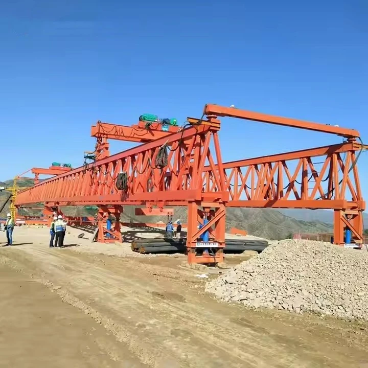
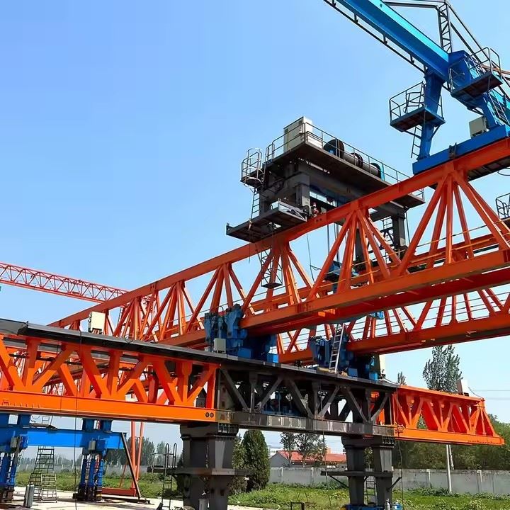
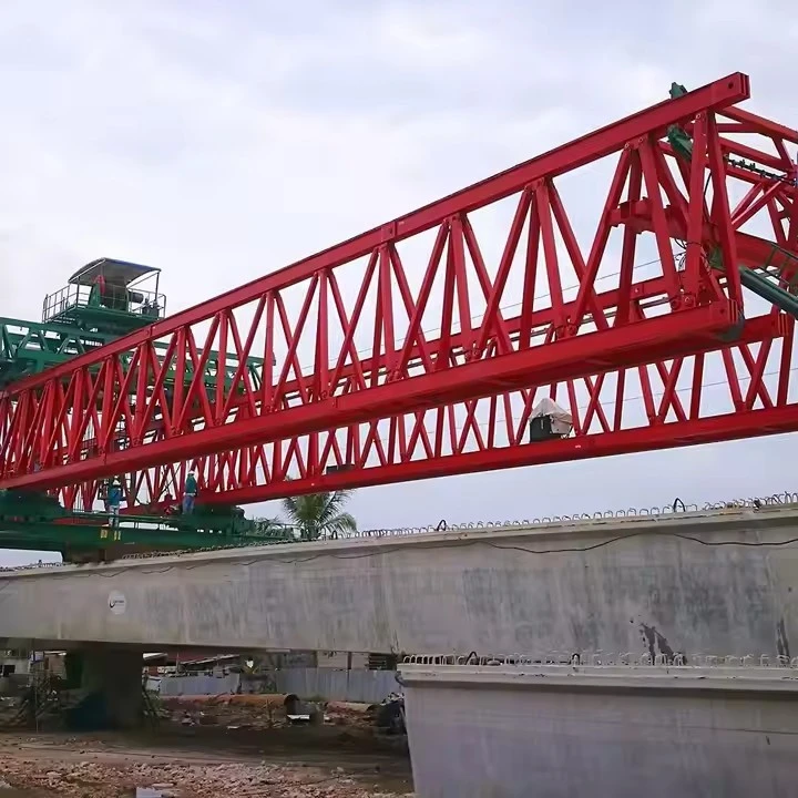
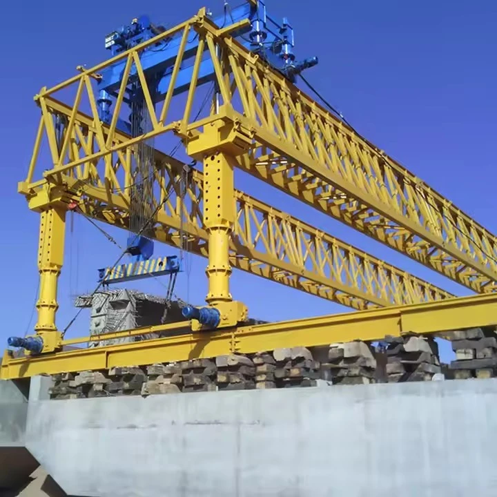
The 180T Bridge Erecting Machine (also known as a Bridge Beam Launcher or Girder Erection Equipment) is a specialized heavy-duty construction machine designed for the precise installation of precast concrete beams (including T-beams, box girders, and U-beams) onto bridge piers. It is an indispensable tool for modern infrastructure projects, including highways, high-speed railways, urban viaducts, and bridges spanning rivers or valleys

The 180T Bridge Erecting Machine is engineered for high efficiency, precision, and safety in large-scale bridge construction. Its features can be categorized into structural design, operational capabilities, adaptability, and intelligent systems.
1. Robust & Optimized Structural Design
The equipment features a well-engineered structure to provide the strength and stability required for heavy-duty lifting, while maintaining ease of transport and assembly.
Main Structure Options: The machine is available in two primary configurations based on the main girder.
Triangular Truss Structure: This is a common and highly stable design for models like the JQJ series, offering an excellent strength-to-weight ratio for longer spans (up to 50m).
Continuous Single Main Beam: Featured in the DJ180 series, this design offers a simpler structure, is easier to assemble, and allows the entire machine to traverse laterally for precise beam placement.
Compact Design for Efficiency: The main beam is designed to be as short as possible while maintaining optimal performance. A shorter beam improves the machine's ability to adapt to complex working conditions, reduces the space needed for operation, and facilitates self-launching ("through-hole") operations.
2. High-Precision & Versatile Operation
The machine is equipped with sophisticated mechanisms for accurate beam handling and placement.
Full Lateral Movement: The entire machine can move transversely, enabling the precise positioning of edge beams and allowing for single-step beam installation, which significantly speeds up the process.
Adjustable Lifting System: The lifting trolley features variable frequency adjustable speeds for both loaded and empty operations. This provides smooth and controlled lifting and lowering of the heavy 180-ton beams.
Adaptable to Various Bridge Types: The machine is capable of handling different bridge geometries, including:
Skew Bridges: Can adapt to skew angles of up to 45 degrees.
Curved Bridges: Can operate on curved sections with a minimum radius of approximately 300 meters (and down to 200m for smaller models).
3. Exceptional Adaptability to Challenging Terrain
This equipment is built to perform reliably in diverse and difficult construction environments.
Handling Steep Slopes: The machine can operate effectively on significant longitudinal and cross slopes, with some models capable of handling a 7% longitudinal gradient thanks to its hydraulic support legs.
Variable Span Capability: It can be adjusted to erect beams of different spans (e.g., 32m, 40m, 50m) within a single project, providing excellent flexibility.
"C" Shape Column Technology: Some models incorporate a "C" shape column design on one of the rear supports. This technology saves transverse space during travel and enables the machine to navigate through tunnels while carrying the girder transfer vehicle.
4. Intelligent Control & Comprehensive Safety
Safety and reliability are at the core of the machine's design, featuring multiple systems to protect both personnel and equipment.
Advanced Control System: The machine typically features a PLC (Programmable Logic Controller) for automated and synchronized lifting operations, simplifying complex maneuvers and enhancing precision.
Multiple Safety Features: Key safety systems include:
Wind Resistance: Designed to operate safely in high winds, with a maximum working wind resistance typically at Force 6 and a higher resistance for empty-load travel (e.g., Force 8).
Comprehensive Protection: Equipped with overload protection, emergency stop systems, and wind speed monitors to ensure operational safety.
Remote Operation: The machine can be operated via a wired button or a wireless remote control, allowing the operator to maintain a safe distance.
5. Ease of Assembly & Transport
Modular Design: The structural components are designed for easy on-site assembly and disassembly, with the heaviest single part weighing approximately 7 tons, which simplifies logistics and crane requirements.
Self-Launching Capability: The machine can move forward to the next span ("through-hole") on its own, significantly reducing the need for auxiliary cranes or heavy transport equipment.
6. Certification & Standards
The machine meets international quality and safety standards, ensuring it is a reliable choice for projects worldwide. It is commonly available with CE, ISO, and GOST certifications.
Key Design Parameters & Performance Specifications
| Parameter | Specification |
|---|---|
| Lifting Capacity (per girder) | 180 Metric Tons |
| Maximum Span (Pier to Pier) | 50 meters (Typical), customizable up to 60m |
| Minimum Curve Radius | 2,000 meters (can be designed for tighter radii) |
| Maximum Supported Grade | ±4% |
| Lifting Hoists | 2 x Main Hoists (typically 120-ton capacity each) |
| Hoist Lifting Speed | 0-5 m/min (variable speed control) |
| Trolley Traversing Speed | 0-10 m/min (variable speed control) |
| Main Beam Launching Speed | 0-5 m/min (variable speed control) |
| Machine Self-Propelling Speed | 0-5 m/min (variable speed control) |
| Control System | Centralized PLC with frequency control for all motions. Remote control operation. |
| Power Supply | 380V / 50Hz / 3 Phase (or as per project requirement) |

Pictures & Components
🏗️ 1. Main Structure & Support System
This is the "backbone" and "legs" of the machine, providing the primary load path and stability.
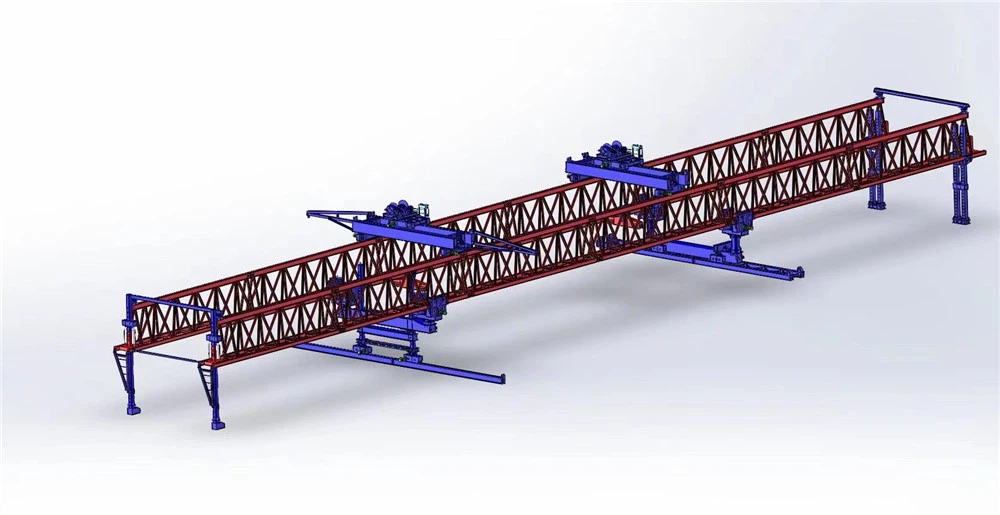
Main Beam / Machine Arm (机臂/主梁): The core load-bearing structure of the machine, typically a continuous single main beam (as in DJ180) or a double-beam truss structure (as in JQJ series), designed to carry the full 180-ton load.
Support Legs (支腿): These vertical supports bear the weight and transfer it to the bridge piers or deck. A typical configuration includes:
Zero/No. 0 Leg (零号柱): The front-most leg, positioned on the target pier ahead.
No. 1, 2, 3 Legs (一号柱, 二号柱, 三号柱): The main support legs along the machine's body, often with hydraulic systems for adjustment.
Outriggers & Stabilizers: Provide additional balance and stability during the lifting and launching operations.
🏗️ 2. Traveling & Positioning System
This system is responsible for moving the entire machine forward and positioning the beams with precision.
Longitudinal Traveling Mechanism: Allows the entire machine to move forward ("self-launch") from one span to the next.
Transverse (Cross) Traveling Mechanism: Enables the whole machine or the lifting trolley to move sideways for precise alignment of the beam, which is crucial for placing edge beams in a single operation.
Wheel Assemblies & Rails: The wheels and rails on which the machine and its trolleys travel.
🏗️ 3. Lifting Mechanism
This is the "workhorse" responsible for hoisting and moving the concrete beams.
Lifting Trolley / Beam Trolley (吊梁行车/起重小车): The traveling unit on the main beam that carries the hoist and is responsible for moving the beam longitudinally.
Wire Ropes, Hooks, and Spreader Beams: The rigging components used to safely attach to and lift the heavy precast beam.
Winches and Hoists: The powered units that drive the lifting operation.
🏗️ 4. Power & Control Systems
The "brain" and "muscle" that power and direct all operations.
Electric Motors & Gearboxes: Provide the motive power for hoisting, traveling, and launching motions.
Hydraulic System (电液系统): Used for jacking, leveling, and making precise adjustments to the legs and other components.
PLC Control System: Acts as the central computer, automating and synchronizing complex lifting and traveling sequences for safety and precision.
Operator Cabin & Sensors: The control interface for the operator, incorporating sensors like limit switches, load cells, and inclinometers for real-time monitoring and safety.
🛡️ 5. Safety & Auxiliary Systems
Essential components for safe operation and on-site practicality.
Safety Systems: Includes overload protection, emergency stops, wind speed monitors, and anti-sway devices.
Cable Reels & Power Supply: Manages the power cables to prevent tangling during movement.
Maintenance Platforms & Ladders: Provide safe access for inspection and maintenance.
The specific configuration can vary slightly between models like the DJ180 and JQJ series, but the functional systems described above form the foundation of all 180T bridge erecting machines

Sketch

Advantages
🚀 Superior Performance & Adaptability
The 180T bridge erecting machine is designed to handle complex construction challenges with high precision.
High Precision & Versatility: A significant advantage is its ability to erect "edge beams in a single placement" (bian liang yi ci dao wei). This capability is facilitated by the machine's ability to move transversely as a whole unit, enabling precise placement of beams that are not in the center of the bridge deck.
Adaptability to Demanding Conditions: The equipment is highly adaptable and can operate effectively on steep longitudinal and cross slopes (up to 5%), on curved bridge sections, and can accommodate various bridge spans (e.g., 32m for railways, 40m for highways). This ensures it can be used in diverse geographical and project-specific scenarios.
🏗️ Enhanced Efficiency & Self-Sufficiency
Modern versions of this machine are engineered to streamline the construction process and reduce reliance on auxiliary equipment.
Self-Launching Without Counterweights: One of the most notable improvements in newer models (often referred to as "third-generation") is the ability to perform the self-launching ("through-hole") operation without needing additional counterweights. This reduces setup time and logistical complexity.
Simplified Logistics: The machine's design often eliminates the need for specialized beam carriers or additional track lines for beam delivery, further simplifying the construction site layout and improving mechanization.
🛡️ Intelligent Safety & Operational Stability
Safety is a core design principle, integrating advanced systems to protect personnel and equipment.
Intelligent Safety Systems: Modern machines are equipped with intelligent limit alarm and anti-overturning technologies that provide real-time monitoring and preventive measures.
Robust & Stable Operation: The equipment is designed for safe and reliable operation under heavy loads and harsh environmental conditions, with certifications such as CE, ISO, and GOST often available to demonstrate compliance with international standards.

Application
The 180T bridge erecting machine is a versatile piece of heavy equipment designed for high-efficiency, large-scale bridge construction, particularly where conventional cranes are impractical. Its primary application is the erection of precast concrete beams (such as T-beams, box girders, and U-beams) in a "span-by-span" method .
🏗️ Key Project Types & Infrastructure
Highways and Expressways: Commonly used for building new highway bridges and viaducts. For example, the JQXD180 model has been used in the construction of the Xizhao Expressway , and the QJ180-40 model was used for a 4x20-meter span municipal bridge in Ezhou .
High-Speed and Conventional Railways: Heavily applied in railway projects for T-beam installation. Notable instances include its use in the Chengdu-Kunming Railway reconstruction project (which used JQXD180 to set a target of erecting 6 T-beams per shift) and the Nanjing hub renovation of the Shanghai-Nanjing-Hefei High-Speed Railway .
Urban Rail and Viaducts: Suitable for erecting various beam types, including U-beams, which are common in urban transit systems .
🌍 Addressing Complex Construction Challenges
The machine excels in scenarios that are difficult for other lifting equipment, such as:
Challenging Terrain: In projects like the Heimaguan Bridge, it navigated steep slopes, sharp curves, and narrow, confined construction zones in mountainous areas to successfully erect 30-meter box girders .
Crossing Obstacles: Designed to build bridges over natural and man-made barriers like rivers, valleys, and existing highways, where ground-based cranes cannot operate effectively .
Complex Engineering Conditions: It is capable of handling special requirements such as erecting beams on skewed bridges (e.g., at a 30-degree angle, achieved by widening support legs) , curved bridge sections, and projects with significant longitudinal slopes . Its ability to handle tunnel-to-bridge transitions and navigate through tunnels with the girder transport vehicle is another advantage, as seen in the Kangxian to Lueyang highway project .

Production Procedure
The production procedure for a 180T bridge erecting machine can be divided into two distinct phases: the manufacturing of its structural components in a factory and the on-site assembly and commissioning required before it can begin work. Because the machine is too large for transport, it is manufactured in sections and assembled at the project site.
🏭 Factory Manufacturing of Main Structural Components
The production of key structural elements, like the main guide beam, follows strict engineering procedures to ensure precision and safety. A representative manufacturing process includes material pretreatment, welding, machining, and assembly.
Step 1: Material Preparation: This initial phase involves selecting the correct materials and preparing them for fabrication. The surfaces of components like connection plates, H-beams, and side plates must be free of corrosion, scars, and defects. They are then subjected to deformation correction, shot blasting for rust removal, and the application of a primer coat.
Step 2: Welding & Quality Control: The side plates are welded onto the H-beam to form a square tube. After welding, the assembly is inspected to ensure weld quality and to remove any slag.
Step 3: Machining & Sub-Assembly: The connection plates and square tubes are precisely machined in a CNC center to create bolt holes according to the design specifications. The parts are then temporarily assembled to form chord members, the fundamental building blocks of the main structure.
Step 4: Main Structure Assembly: Three chords are assembled to form a triangular truss structure. This design provides the high strength-to-weight ratio required for the machine's 180-ton lifting capacity. Gusset plates are welded at the joints to reinforce the structure.
🔧 On-Site Assembly and Commissioning
Once the components are delivered to the construction site, the erecting machine is assembled and commissioned. This process demands careful planning and execution to ensure safety and operational readiness.
Component Ground Assembly: The main body of the bridge erecting machine is assembled at ground level. This is a key step that significantly reduces the amount of high-altitude work required, improving safety and efficiency.
Sequential Lifting and Leg Installation: The main structure is lifted in stages. At specific heights, the rear, middle, and front support legs are installed underneath. This sequence is critical for maintaining stability. For example, the assembly of a DJ180 railway erector follows a specific order: assembling the No. 2 leg, then the boom segments, the traveling trolleys, the No. 1 leg, and finally the No. 0 and No. 3 legs.
Support and Stabilization: As the legs are installed, support frames are placed beneath them, and the main structure is lowered into its final operational position. Wind ropes (cables) may be attached to the side of the structure for added stability during the assembly process.
Final Assembly and Commissioning: The final steps involve installing auxiliary components like the power unit, electrical systems, and hydraulic lines. The machine is then thoroughly inspected, and tests, including load tests, are performed to certify its functionality and safety before it is cleared for operations.
🛠️ Special Considerations for On-Site Erection
Handling Special Span Types: When erecting the first span of a bridge, the foundation under the middle leg's transverse track must be well-compacted to prevent the machine from sinking under the massive load. For the last span, the front leg must be specially adapted to operate directly on the bridge abutment.
Stability and Counterweights: During operation, stability calculations are crucial to prevent overturning. For instance, when erecting a standard 32.6-meter beam, a 180T erecting machine might require additional counterweights to maintain a safe stability coefficient. The weight of its own track components can sometimes be used to provide this necessary ballast.


Workshop View
The company has installed an intelligent equipment management platform, and has installed 310 sets (sets) of handling and welding robots. After the completion of the plan, there will be more than 500 sets (sets), and the equipment networking rate will reach 95%. 32 welding lines have been put into use, 50 are planned to be installed, and the automation rate of the entire product line has reached 85%.


Hot Tags: 180t bridge erecting machine, China 180t bridge erecting machine manufacturers, suppliers, factory
You Might Also Like


Send Inquiry