









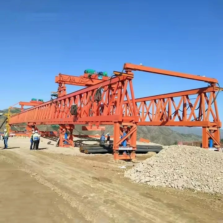
150 Ton Bridge Erecting Machine
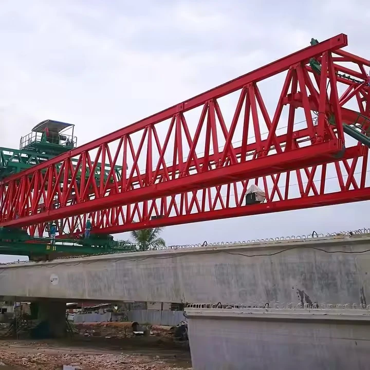
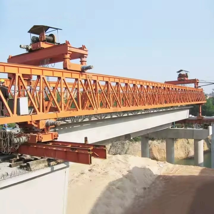
A 150-ton bridge erecting machine is a large, specialized piece of equipment designed for the efficient and precise placement of precast concrete or steel girders in bridge construction.

🏗️ How It Works
The machine uses a self-launching mechanism to move along the completed bridge deck, eliminating the need for constant repositioning of external cranes. The process is a carefully balanced operation:
Positioning: The machine is assembled on a bridge pier and spans to the next support.
Counterbalancing: A heavy counterweight (sometimes up to 150 tons) is placed on the completed section of the bridge to stabilize the machine and prevent it from tipping forward when lifting a new girder.
Lifting & Placement: A trolley system travels along the main girder to the new segment, lifts it from a transport vehicle, and moves it into its precise position on the pier.
Precision Alignment: The machine uses lateral movement systems and hydraulic controls to ensure the girder is placed with high accuracy, reducing errors and rework.
Key Design Parameters & Performance Specifications
| Parameter | Specification |
|---|---|
| Lifting Capacity (per girder) | 150 Metric Tons |
| Maximum Span (Pier to Pier) | 50 meters (Typical), customizable up to 60m |
| Minimum Curve Radius | 2,000 meters (can be designed for tighter radii) |
| Maximum Supported Grade | ±4% |
| Lifting Hoists | 2 x Main Hoists (typically 120-ton capacity each) |
| Hoist Lifting Speed | 0-5 m/min (variable speed control) |
| Trolley Traversing Speed | 0-10 m/min (variable speed control) |
| Main Beam Launching Speed | 0-5 m/min (variable speed control) |
| Machine Self-Propelling Speed | 0-5 m/min (variable speed control) |
| Control System | Centralized PLC with frequency control for all motions. Remote control operation. |
| Power Supply | 380V / 50Hz / 3 Phase (or as per project requirement) |

Pictures & Components
Detailed Explanation of Each Component
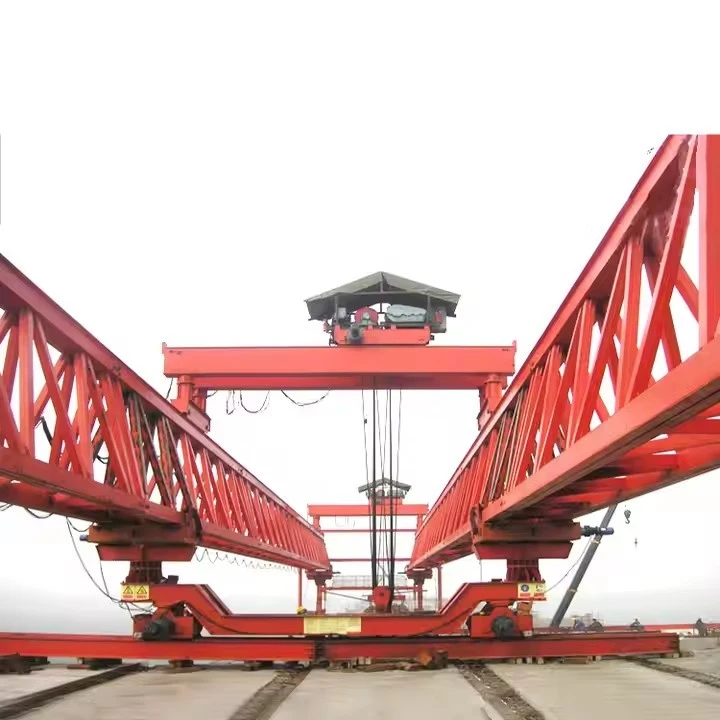
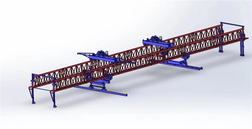
1. Main Girder / Launching Truss
Made of high-strength structural steel.
Provides a rigid track for the lifting trolley to travel along.
Its length typically spans multiple bridge piers (usually 2 to 3 spans).
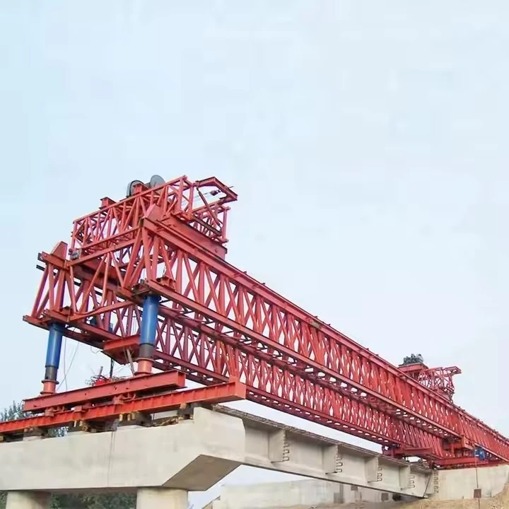
2. Support Legs
Front Leg (Front Support): Erected on the next pier, supporting the front end of the main girder. Often height-adjustable to accommodate varying pier elevations.
Middle Leg (Launching Leg): Positioned near the center of the machine, usually supporting on the girder just placed. It carries most of the load during the launching process.
Rear Leg (Rear Support): Anchored on the completed deck, providing counterbalance and stability.
3. Hoist / Lifting Trolley
Equipped with two synchronized winches to ensure the load is lifted evenly and remains level.
Includes spreader bars to distribute the load across multiple lifting points on the precast girder, preventing stress damage.
4. Electrical & Hydraulic Systems
Hydraulic power packs drive the extension/retraction of legs and the lateral movement of trolleys.
Electrical control uses PLCs (Programmable Logic Controllers) with redundant safety circuits to ensure fail-safe operation.
5. Operator Console & Monitoring System
Equipped with sensors for load weight, tilt angle, wind speed, and leg pressure.
A display screen shows real-time data, allowing the operator to make precise adjustments.
Includes emergency stop and overload alarm functions for safety.
Safety Components (Integrated throughout)
Overload Limiters: Automatically cut power if the lifting weight exceeds 150 tons.
Anti-Tilt Sensors: Trigger alarms if the machine tilts beyond a safe angle.
Wind Speed Anemometers: Require operations to stop when wind speeds exceed safe thresholds.
Emergency Braking Systems: Installed on both hoisting and traveling mechanisms.

Sketch

Advantages
Key Advantages of a 150-Ton Bridge Erecting Machine
🚀 Construction Efficiency Advantages
| Advantage | Description |
|---|---|
| High Daily Output | Capable of erecting 5 to 7 girders per day, significantly shortening overall project timelines. |
| Rapid Deployment | Modular design allows for quick on-site assembly and disassembly, facilitating fast relocation between project sites. Some models offer hoisting speeds up to 20% faster than conventional systems. |
| Automated Operation | Equipped with variable frequency drives and wireless remote controls, enabling one‑key leveling, one‑key bridge launching, and smooth, precise movements. |
🧭 Complex Terrain Adaptability
| Advantage | Description |
|---|---|
| Curve Erection Capability | Articulated main girder designs can accommodate horizontal curves as tight as 75 meters in radius, solving challenges encountered in urban light rail and curved viaduct projects. |
| Steep Grade Adaptation | Capable of handling up to 4% longitudinal slopes and 3% transverse slopes, making it suitable for mountainous and uneven terrains. |
| Flexible Spanning | Maximum spanning capacity ranges from 45 to 60 meters, with the ability to quickly switch between different span lengths (variable span) without major reconfiguration. |
🦾 Safety & Intelligent Systems
| Advantage | Description |
|---|---|
| Multi‑Level Safety Protection | Integrated systems include overload protection, anti‑tilt monitoring, real‑time attitude sensing, and automatic alarms to ensure operational safety at all times. |
| Intelligent Control | Advanced models incorporate AI‑assisted operation to reduce human error, along with environmental perception systems (wind speed, temperature, vibration) for adaptive response. |
| New Energy Application | Some models adopt "range extender + power battery" hybrid technology, reducing fuel consumption by up to 40% while lowering emissions and noise. |
🔩 Structural Design & Durability
| Advantage | Description |
|---|---|
| High‑Strength Materials | Constructed with ASTM A572 Grade 50 high‑strength, corrosion‑resistant steel, ensuring long‑term structural integrity even in harsh environments (coastal, high‑humidity, etc.). |
| Compact & Lightweight | Optimized structure reduces dead weight for easier transport. The heaviest single component typically weighs only 6.6 tons, meeting standard highway transportation limits without special permits. |
| Superior Corrosion Protection | Sealed welding and standardized sandblasting/painting processes effectively prevent internal and external corrosion, extending service life and reducing maintenance costs. |
📊 Summary Table – Advantages at a Glance
| Category | Key Benefits |
|---|---|
| Efficiency | 5–7 girders/day, rapid setup, automated one‑key operations |
| Adaptability | 75m min. curve radius, 4% longitudinal slope, 3% transverse slope, up to 60m span |
| Safety & Intelligence | Overload/anti‑tilt sensors, AI assistance, real‑time monitoring, up to 40% fuel savings |
| Durability | ASTM A572 steel, lightweight transport (6.6t max piece), corrosion‑resistant coating |

Application
💼 Main Applications
| Application Area | Description |
|---|---|
| Highway & Expressway Construction | A primary use for projects like the Shanan Expressway A4 Project in China, where a 150-ton machine was used to successfully erect T-beams that were 40 meters long and weighed 150 tons . These machines are designed for stable operation under heavy loads in long-span highway projects . |
| Railway & High-Speed Rail Projects | Used for erecting box girders and other precast beams on railway lines . They are crucial for the efficient, span-by-span construction of standard and non-standard double-line prestressed concrete box girders . |
| Urban Viaducts & Overpasses | Ideal for building elevated roads in densely populated cities where construction space is limited. A notable application is the urban viaduct construction project in Malaysia, which successfully used a machine with a small curve radius and bottom-feeding beam technology to solve challenges in confined spaces . They are also used in urban rail transit systems like subways and light rail . |
| Large-Span Special Bridges | Essential for constructing long-span bridges that cross rivers, lakes, or straits . For instance, a DP150/60 model was employed on the Mumbai Trans-Harbor Link project in India to erect segmental beams with a maximum span of 60 meters . These machines are also adaptable for overpasses and bridges spanning valleys or other highways . |

Production Procedure
📋 Production Procedure of a 150-Ton Bridge Erecting Machine
| Stage | Key Activities | Description |
|---|---|---|
| 1. Project Definition & Engineering | Client requirement analysis; conceptual/detailed design; FEA structural analysis; mechanical, electrical, and control system design; procurement planning. | The process begins with a detailed review of technical specifications (e.g., span length, max lifting capacity, environmental conditions). Engineering teams use 3D modeling and finite element analysis to validate the structural integrity of the main beams and components . |
| 2. Material Procurement & Inspection | Sourcing of high-strength steel plates (e.g., Q345B, Q460C); incoming quality control (IQC); material certificate verification; ultrasonic testing (UT) of steel plates. | High-grade steel is procured. Upon arrival, all materials are rigorously inspected to ensure they meet the required mechanical properties and are free of internal flaws . This step is critical for load-bearing components. |
| 3. Steel Structure Fabrication | Cutting: CNC plasma/oxy-fuel cutting of steel plates to size. Welding: Submerged Arc Welding (SAW) for main truss/box girders. Assembly: Fabrication of main girders, cross beams, and structural frames. |
This is the core manufacturing phase. Advanced fabrication techniques are used to cut and shape steel components. Critical structural joints are welded using processes like SAW to ensure deep penetration and strength . |
| 4. Quality Control (NDT) | Non-Destructive Testing (NDT): Ultrasonic Testing (UT) and Magnetic Particle Testing (MT) on critical welds. | All critical welds undergo NDT to detect internal or surface defects. This ensures the structural integrity and safety of the machine . |
| 5. Precision Machining | Machining of wheel assemblies, bearing housings, pin shafts, and connection joints. | Precision machining is performed on critical moving parts and connection points. This ensures proper alignment, smooth operation, and long-term durability . |
| 6. Component Manufacturing & Sub-Assembly | Production of key systems: lifting winches, trolleys, hydraulic cylinders, power packs, and support mechanisms. | Individual systems like the lifting mechanism, hydraulic system, and electrical control panels are manufactured and sub-assembled. Each component is often tested individually before the final assembly . |
| 7. Pre-Assembly & Load Testing | Full assembly of the machine at the factory; load testing (often with test weights) to verify lifting capacity and safety. | The entire machine is assembled at the factory to verify fit and function. A crucial step is the load test, where the machine lifts test weights up to its maximum capacity (150 tons) to confirm performance and safety . |


Workshop View
The company has installed an intelligent equipment management platform, and has installed 310 sets (sets) of handling and welding robots. After the completion of the plan, there will be more than 500 sets (sets), and the equipment networking rate will reach 95%. 32 welding lines have been put into use, 50 are planned to be installed, and the automation rate of the entire product line has reached 85%.


Hot Tags: 150 ton bridge erecting machine, China 150 ton bridge erecting machine manufacturers, suppliers, factory
You Might Also Like


Send Inquiry