










180T Bridge Beam Launcher For Bridge Construction manufacturers

180T Bridge Beam Launcher For Bridge Construction suppliers

180T Bridge Beam Launcher For Bridge Construction factory

180T Bridge Beam Launcher For Bridge Construction best

180T Bridge Beam Launcher For Bridge Construction high quality

180T Bridge Beam Launcher For Bridge Construction price
180T Bridge Beam Launcher For Bridge Construction

⚙️ How It Works: Key Systems
The launcher functions as a mobile, high-precision factory on the bridge deck:
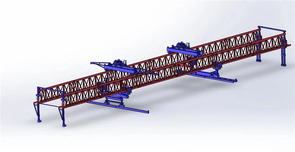
Structure and Support: It consists of a large main beam or truss, supported by front and rear legs that rest on the bridge piers or the newly erected deck. Hydraulic systems are used for leveling and adjusting the machine's stance.
Material Handling: Precast girders are delivered to the rear of the launcher by a dedicated beam trolley. The launcher's twin hoists or trolleys then lift the girder and travel longitudinally along the main beam to position it over the intended span.
Precise Placement: Once in position, the trolleys can move transversely to align the girder with millimeter-level accuracy before gently lowering it onto the bearings.
Self-Launching: A key feature is its ability to move itself to the next span. By using its legs and support systems to "walk" or "crawl" forward along the completed section, it eliminates the need for dismantling and reassembly.
Specifications
Key Design Parameters & Performance Specifications
| Parameter | Specification |
|---|---|
| Lifting Capacity (per girder) | 180 Metric Tons |
| Maximum Span (Pier to Pier) | 50 meters (Typical), customizable up to 60m |
| Minimum Curve Radius | 2,000 meters (can be designed for tighter radii) |
| Maximum Supported Grade | ±4% |
| Lifting Hoists | 2 x Main Hoists (typically 120-ton capacity each) |
| Hoist Lifting Speed | 0-5 m/min (variable speed control) |
| Trolley Traversing Speed | 0-10 m/min (variable speed control) |
| Main Beam Launching Speed | 0-5 m/min (variable speed control) |
| Machine Self-Propelling Speed | 0-5 m/min (variable speed control) |
| Control System | Centralized PLC with frequency control for all motions. Remote control operation. |
| Power Supply | 380V / 50Hz / 3 Phase (or as per project requirement) |

Pictures & Components
🏗️ 1. Main Structure (Load-Bearing Frame)
| Component | Function |
|---|---|
| Main Girder / Truss | The primary horizontal steel structure that carries the full lifting load (180T). Typically a double-box or twin-truss design for high rigidity and stability. |
| Front Support Leg (Front Mast) | Telescopic or folding leg that rests on the front pier or the next span's support. Transfers load to the bridge substructure. |
| Rear Support Leg (Rear Mast) | Positions on the already erected deck or the rear pier. Provides counterbalance and stability during lifting and launching. |
| Auxiliary Leg / Middle Leg | Used during the self-launching (walking) phase to temporarily support the machine while the main legs are relocated. |
🏗️ 2. Lifting & Traveling System (Material Handling)
| Component | Function |
|---|---|
| Lifting Trolleys (Hoists) | Usually two synchronized trolleys running along the main girder. Each is equipped with wire rope hoists and pulleys to lift the 180T beam from the delivery trolley. |
| Spreader Beam | A crossbeam attached between the hoists and the precast girder. Distributes the lifting force evenly across the girder to prevent cracking or damage. |
| Longitudinal Travel Drive | Motors and gearboxes that move the trolleys forward/backward along the main girder to transport the beam from the rear loading zone to the placement position. |
| Transverse Adjustment Mechanism | Hydraulic or screw-driven system that allows lateral (side-to-side) movement of the trolley for fine alignment (±50–100mm typical) over the bearings. |
🏗️ 3. Hydraulic System (Power & Control)
| Component | Function |
|---|---|
| Hydraulic Power Pack | Centralized pump unit (electric motor + hydraulic pump) providing pressurized oil to all actuators. Typical power ~90–100 kW. |
| Leveling Jacks / Cylinders | Located at each leg. Used to level the launcher on uneven piers and to adjust the machine's attitude (slope, skew). |
| Telescopic Cylinders (Legs) | Extend/retract the front and rear legs for height adjustment and for clearance during the self-launching process. |
| Slewing / Rotation Cylinders | Allow limited rotation of the launcher to accommodate skew-angled bridges (up to 45°). |
| Walking Cylinders (Step-Type Launchers) | In "step-type" designs, these cylinders lift the entire machine and move it forward incrementally (like a walking gait) for self-relocation. |
🏗️ 4. Control & Safety Systems
| Component | Function |
|---|---|
| Control Cabin | Operator's station, usually mounted on the main girder. Equipped with joysticks, displays, and indicator lights for real-time load, tilt, and position monitoring. |
| PLC Controller | Programmable logic controller that manages synchronized lifting, travel speed, and load-sharing between the two trolleys to ensure safe, coordinated movement. |
| Load Cells / Pressure Sensors | Installed on the hoist lines and hydraulic cylinders to display real-time lifting weight and prevent overload (critical for 180T capacity). |
| Limit Switches & Proximity Sensors | Prevent over-travel of trolleys, over-extension of legs, and collision with obstacles. |
| Anemometer (Wind Sensor) | Monitors wind speed; operation is halted if wind exceeds safe limits (typically >6–7 Beaufort). |
| Emergency Stop System | Redundant kill-switches located both in the cabin and on the deck for immediate power cutoff in emergencies. |
🏗️ 5. Mobility & Self-Launching Mechanism
| Component | Function |
|---|---|
| Wheel Assemblies (Roller Units) | Mounted on the legs to allow the launcher to move along the bridge deck or piers. Can be motorized or rely on hydraulic pushing. |
| Rail Track | Often used on the deck to guide the launcher's wheels during forward movement. Laid temporarily and moved forward as the machine advances. |
| Guide Pulleys / Side Rollers | Keep the launcher aligned on the track, preventing lateral drift during the self-launching phase. |
| Pin-Connection System | Allows the front leg to be detached, folded, or raised to clear the pier during the walk to the next span. |
🏗️ 6. Ancillary / Support Components
| Component | Function |
|---|---|
| Beam Delivery Trolley | A separate wheeled transporter that brings the 180T precast girder from the casting yard or storage area to the rear of the launcher. |
| Spreader Bar / Lifting Frame | (Reinforced) – mentioned above, but often considered a removable accessory. |
| Counterweights | Added to the rear of the launcher during lifting to maintain stability and prevent forward tipping. |
| Hydraulic Hoses & Fittings | High-pressure lines connecting the power pack to all cylinders, with quick-connect couplings for modular assembly/disassembly. |
| Walkways & Guardrails | Installed along the main girder for safe access during inspection and maintenance. |
| Lighting System | Work lights for night or low-visibility operations. |

Sketch

Advantages
🚀 Core Advantages of a 180T Bridge Beam Launcher
1. High Efficiency & Speed
The beam launcher enables span-by-span erection without dismantling equipment, significantly reducing the cycle time for placing each girder . Modern models, such as the third-generation JQJ45m-180T, are specifically designed to greatly improve beam erection efficiency, making them ideal for long viaducts and projects with repetitive spans .
2. Superior Site Adaptability
It can operate in difficult environments where ground cranes are impractical, such as over rivers, deep valleys, busy highways, or in urban areas with restricted access . The launcher works above ground, so it doesn't depend on terrain conditions below, eliminating the need for large access roads or extensive ground support . Some models are also designed for small-radius curves and skew bridges .
3. High-Precision Installation
Equipped with synchronized lifting and positioning systems, the launcher allows for the accurate alignment of heavy girders. This minimizes installation errors and rework, which is particularly critical for high-speed railway and other precision-demanding projects . Features like "one-time positioning of side beams" further enhance accuracy .
4. Cost-Effectiveness (for Large Projects)
While the initial investment is high, the launcher is cost-effective on large-scale projects by reducing :
Crane rental costs
The need for temporary support structures
Labor requirements
Costs associated with site leveling and land acquisition
5. Enhanced Safety
The launcher's stable structure supported on bridge piers provides a safer alternative to lifting over open ground with cranes . It integrates numerous safety features, including :
Overload protection systems with load sensors
Anti-sway mechanisms to stabilize the load
Intelligent limit controls and anti-tipping technology
Emergency stop buttons and limit switches
6. Self-Launching Capability
A major advantage is its ability to move itself forward from one span to the next without the need for dismantling and reassembly . Some advanced models can perform this "through-hole" process without requiring counterweights, saving significant time and labor . It can also be designed to not require longitudinal moving tracks, reducing pressure on the newly laid deck .
7. Versatility
The launcher is highly versatile and can handle :
Different girder types (T-shaped, I-shaped, U-shaped, and box girders)
Straight, curved, and skew bridges
Both highway and railway applications
8. Reduced Environmental Impact
By operating above ground, the launcher causes minimal ground disturbance and reduces the need for temporary roads or heavy equipment below the bridge. This is a significant advantage for environmentally sensitive areas or projects with high environmental protection requirements .
9. Lightweight & Easy Assembly
Many modern launchers feature a lightweight design that makes transportation, installation, and removal more convenient . The use of modular designs helps save on equipment costs .

Application
🏗️ Primary Applications of a 180T Bridge Beam Launcher
A 180T bridge beam launcher is a specialized machine used wherever large precast concrete girders need to be installed efficiently and safely-especially in projects where traditional cranes are impractical or impossible to use . Below are its main real-world applications.
🌉 Highway & Expressway Bridge Construction
The launcher is widely used for erecting precast concrete girders on expressways, urban flyovers, and elevated highways . It is particularly effective for long elevated road sections with repetitive spans, where its span-by-span erection method dramatically speeds up construction . In urban areas, it allows construction to proceed above active traffic, minimizing disruption to vehicles and pedestrians below .
🚄 Railway & High-Speed Rail Bridges
For railway viaducts and high-speed rail lines, the launcher is an essential piece of equipment . It can handle the heavy prestressed concrete girders commonly used in rail systems and ensures the high-precision alignment required for rail safety and smooth train operation . The DJ180 model, for example, is specifically designed for both highway bridges up to 40m spans and railway bridges up to 32m spans .
🌁 Viaducts & Long Multi-Span Structures
The machine excels in constructing multi-span viaducts across valleys, floodplains, and urban corridors . Its ability to perform continuous span-by-span construction over long distances makes it ideal for large-scale infrastructure projects like the JQJ45m-180T, a third-generation launcher developed for linear road and bridge projects . This model is designed for step-type hole-crossing without requiring counterweights, further improving efficiency .
🌊 Bridges Over Rivers & Water Bodies
When building bridges over rivers, lakes, or straits, the launcher eliminates the need for temporary scaffolding in the water, floating cranes, or barges . This is especially valuable where water conditions are deep, fast-moving, or otherwise difficult, allowing construction to proceed safely from the bridge deck above .
🏙️ Urban Infrastructure & Transit Projects
In cities, the launcher is used for metro lines, light rail systems, and elevated road networks . It minimizes disruption to surrounding buildings, utilities, and traffic-a critical advantage in densely built environments where ground space is limited . The machine's compact footprint and ability to operate above ground keep cities functioning during construction.
⛰️ Mountainous & Difficult Terrain
The launcher is highly suitable for areas where ground access is limited or heavy cranes cannot be deployed . In hilly, remote, or mountainous regions, it can operate on slopes of up to 5% gradient and navigate small-radius curves and skew bridges, adapting to complex site conditions . This makes it a practical solution for infrastructure development in challenging geography.
🔄 Bridge Widening, Rehabilitation & Girder Replacement
The launcher can be adapted for upgrading existing infrastructure-including adding new girders to widen bridges or replacing old, deteriorated beams . This capability allows agencies to upgrade structures without full closure, reducing traffic disruption and extending the service life of aging bridges .
🏗️ Large-Span Special Bridges
For large-span bridges crossing wide waterways or straits, the launcher provides the load-bearing capacity and operational precision required . Studies have also documented its successful use in cable-stayed bridge construction, where it contributes to both efficiency and construction quality .

Production Procedure
🏭 Phase 1: Factory Manufacturing
The factory phase ensures the structural integrity and reliability of the equipment before it arrives on site.
Design & Engineering: The process begins with a detailed analysis of the project's specific requirements, such as lifting capacity, beam length, and span. This includes structural analysis and Finite Element Analysis (FEA) to produce General Arrangement (GA) and fabrication drawings.
Raw Material Procurement & Inspection: High-grade steel (like Q345B or Q420) is selected and inspected for mechanical properties and surface defects to ensure it meets standards.
Steel Structure Fabrication:
Cutting & Forming: CNC flame/plasma cutting machines are used to accurately cut steel plates.
Welding: Critical components like main truss beams are welded using processes like Submerged Arc Welding (SAW), while secondary structures often use CO₂/MIG welding.
Welding Inspection & Quality Control (QC): All critical welds undergo Non-Destructive Testing (NDT), typically using Ultrasonic Testing (UT) and Magnetic Particle Testing (MT) to detect internal and surface flaws.
Machining & Precision Processing: Precision components such as wheel assemblies, bearing housings, and pin shafts are machined to ensure smooth operation and durability.
Sub-Assembly: Key systems, including lifting winches, hydraulic cylinders, and control mechanisms, are assembled and tested individually.
Pre-Assembly (Factory Trial Assembly): A partial or full assembly is conducted in the factory to check structural alignment and fit-up accuracy, which helps ensure smooth on-site installation.
Electrical & Hydraulic System Installation: All electrical (PLC, sensors) and hydraulic (pumps, valves) systems are installed, followed by thorough insulation and grounding tests.
Surface Treatment & Painting: The structure undergoes shot blasting (to Sa2.5 standard) to prepare the surface, followed by anti-corrosion primer and topcoats for weather protection.
Factory Testing & Commissioning:
Functional Testing: Hoisting and travel movements are verified.
Load Testing: A static load test at 125% of the rated load and a dynamic load test at 110% are performed to prove its capacity and safety.
Disassembly, Packing & Delivery: The launcher is disassembled into modular sections and carefully packed for transport via container or bulk shipment.
🏗️ Phase 2: On-Site Installation & Erection Process
Once on location, the launcher is assembled and put to work on the bridge.
On-Site Installation & Commissioning: The structural components are assembled on the bridge piers or abutments. After installing mechanical and electrical systems, the unit undergoes final alignment and a test run.
Beam Erecting Operation (the workflow on the project):
Precast Beam Fabrication: Concrete beams (T-type, I-type, or box girders) are cast, cured, and inspected in a precast yard.
Transport & Positioning: Beams are delivered by trailers to the launcher's working area.
Lifting & Traveling: The launcher's hoisting system lifts the beam, and trolleys carry it longitudinally along the main girder to the target span.
Placement & Alignment: The beam is accurately lowered and aligned onto the bearings on the piers.
Self-Launching to Next Span: After all beams in a span are set, the launcher uses its own mechanism to move forward to the next span, repeating the cycle.


Workshop View
The company has installed an intelligent equipment management platform, and has installed 310 sets (sets) of handling and welding robots. After the completion of the plan, there will be more than 500 sets (sets), and the equipment networking rate will reach 95%. 32 welding lines have been put into use, 50 are planned to be installed, and the automation rate of the entire product line has reached 85%.


Hot Tags: 180t bridge beam launcher for bridge construction, China 180t bridge beam launcher for bridge construction manufacturers, suppliers, factory
You Might Also Like


Send Inquiry