










150ton Counterweight Bridge Erecting Machine
A 150-ton Counterweight Bridge Erecting Machine is a marvel of modern civil engineering, enabling the safe and efficient construction of massive bridges in locations where it was once thought impossible. Its core innovation is the use of a counterweight to manage the immense forces involved in building a bridge outwards from a single point.

How It Works: The Step-by-Step Process
Step-by-Step Working Principle (Balanced Cantilever Method)
The process for a single pier is highly methodical:
Setup: The machine is assembled on top of a bridge pier, with its support legs firmly anchored.
Segment Delivery: A 150-ton pre-cast segment is delivered by a multi-axle trailer and positioned directly beneath the lifting hoists.
Lifting & Counterbalancing:
The hoist on one side of the pier lifts a segment.
Simultaneously, the counterweight system on the opposite side is engaged (either by moving weights or by having a fixed counterweight designed for the load).
This creates a balanced condition, like a seesaw with equal weights, keeping the pier and machine stable.
Placement & Adjustment: The segment is precisely positioned against the previously placed segment. High-strength epoxy is applied to the mating surface, and temporary post-tensioning bars are installed to hold it in place.
Balanced Erection: The process is repeated on the other side of the pier to maintain symmetry and balance. The machine alternates sides, placing one segment on the left, then one on the right, and so on, progressively building out the bridge deck in both directions.
Post-Tensioning: After several pairs of segments are placed, permanent internal or external steel tendons are threaded through the segments and tensioned with massive jacks. This compresses the entire assembly, turning individual segments into a single, strong, continuous span.
Launching: Once the cantilever is complete and can support itself, the machine is disengaged, propelled forward over the newly built deck, and set up on the next pier to repeat the entire process.
Specification
1.0 General Description
The 150-Ton Counterweight Bridge Erecting Machine is a self-contained, modular, and electrically powered gantry system designed for the rapid and safe erection of precast concrete bridge girders, specifically I-girders, U-girders, and T-beams. The machine utilizes a balanced cantilever method with a rear counterweight system to maintain stability during the launching and girder placement process. It is characterized by its high efficiency, minimal requirement for ground support, and adaptability to various bridge geometries.
2.0 Key Design Parameters & Performance Specifications
| Parameter | Specification |
|---|---|
| Maximum Lifting Capacity | 150 Metric Tons per girder |
| Suitable Span Range | 20m to 40m (typical); can be designed for up to 50m |
| Maximum Girder Length | 40 meters (adjustable based on project) |
| Girder Types | Precast I-Girders, U-Girders, T-Beams |
| Applicable Bridge Width | Adaptable for erecting 2 to 4 girders per span |
| Minimum Horizontal Curve Radius | ≥ 1500 meters |
| Maximum Longitudinal Gradient | ±3% |
| Lifting Hoist Travel Speed | 0.5 ~ 1.0 m/min (adjustable) |
| Gantry Traversal Speed | 3 ~ 5 m/min |
| Machine Self-Propelled Speed | 5 ~ 10 m/min |
| Control System | Centralized PLC with RF Remote Control |

Pictures & Components
The components can be categorized into several main systems:
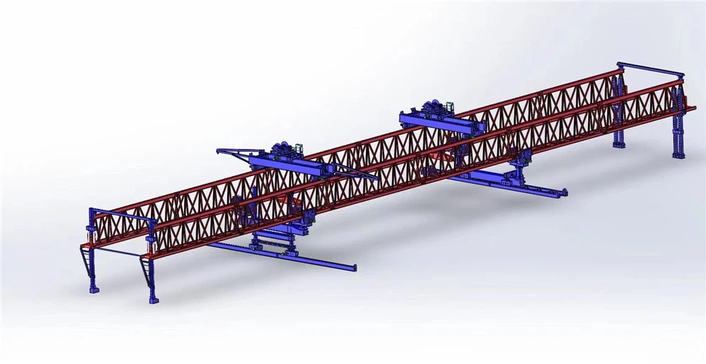
1. Main Structural Steel Frame
This is the primary skeleton of the machine that carries all the loads.
Main Gantry Beams (Girders): Two large, heavy-duty steel box girders or trusses that run the entire length of the machine. They provide the primary support and guide the lifting system.
Front Support Leg: A vertical or A-frame structure at the front of the machine. It transfers the load to the already constructed bridge deck or a pier.
Rear Support Leg: The critical component that interfaces with the counterweight. It also rests on the bridge deck and is designed to handle the massive uplift and compressive forces.
Cross Beams: Horizontal beams connecting the two main girders, ensuring structural stability and providing attachment points for other components.
2. Support and Mobility System
This system allows the machine to "walk" forward as the bridge is constructed.
Support Shoes / Jacking Pads: Large, robust plates at the bottom of the support legs that distribute the concentrated load onto the bridge deck to prevent damage.
Temporary Bearings: Used to securely lock the machine onto the bridge pier or deck during segment erection.
Propulsion System:
Hydraulic Jacks (Traction Cylinders): These are the "muscles" that pull or push the machine forward.
Walking Skids / Sliding Shoes: Low-friction surfaces that the machine slides on during launching.
Reaction Brackets: Anchors fixed to the bridge deck that the traction jacks push against to move the machine.
3. Lifting and Handling System
This is the core system responsible for picking up, moving, and placing the 150-ton concrete segments.
Main Hoists (Lifting Gantries): Typically two or more powerful winches or hoists that travel along the main girders.
Hoist Winch: A high-capacity, electrically or hydraulically driven winch with a robust brake system.
Wire Rope: High-strength steel cable capable of handling the 150-ton load with a significant safety factor.
Sheaves / Pulleys: Heavy-duty blocks that guide the wire rope.
Lifting Frames / Spreaders: A rigid steel frame that connects to the segment. It ensures the load is lifted evenly and prevents excessive bending moments in the precast segment. It often includes fine-adjustment cylinders for precise positioning.
Trolley: The wheeled assembly that the hoist is mounted on, allowing it to traverse the length of the main girders.
4. The Counterweight System
This is the defining feature that balances the machine and prevents it from tipping over.
Counterweight Blocks: Massive, dense blocks, typically made of concrete or steel. For a 150-ton machine, the total counterweight could be in the range of 1000 to 2000 tons or more, depending on the design and reach.
Counterweight Carrier / Platform: A strong structural frame at the rear of the machine that holds the counterweight blocks.
Counterweight Lifting Mechanism: A smaller, dedicated hoist or hydraulic system used to add or remove counterweight blocks as needed during the launching cycle.
5. Hydraulic System
The "lifeblood" of the machine, providing power for most movements.
Hydraulic Power Unit (HPU): The central unit containing reservoirs, pumps, filters, and coolers.
Hydraulic Cylinders: Used for:
Propulsion (traction jacks)
Lifting frame adjustment
Leg jacking and leveling
Operating clamps and locks
Control Valves & Manifolds: Direct the flow of hydraulic fluid to the various actuators.
Hoses and Piping: High-pressure lines that transport the hydraulic fluid.
6. Electrical and Control System
The "nervous system" that coordinates all operations.
Main Control Cabin: An enclosed operator's station with joysticks, switches, and display screens, usually located for optimal visibility.
Programmable Logic Controller (PLC): The computer that automates sequences, monitors sensors, and ensures safety interlocks.
Frequency Drives: For smooth control of hoist and trolley motors.
Sensors:
Load Cells: To measure the weight of the lifted segment and the counterweight.
Limit Switches: To prevent over-travel of moving parts.
Inclinometers: To monitor the level of the entire machine.
Laser Positioning Systems: For precise alignment of segments.
Power Distribution: Transformers, circuit breakers, and cabling to deliver electricity to all motors and systems.
7. Auxiliary and Safety Systems
Anchoring and Bracing: Temporary ties and bracing rods to secure the machine against wind and seismic loads.
Safety Gates and Walkways: For personnel access and maintenance.
Lighting: For night operations.
Emergency Stop Systems: Redundant, hard-wired systems to halt all machine functions immediately.
Storm Tie-Downs: Provisions for securing the machine during severe weather.
How the Components Work Together in a Typical Cycle:
Positioning: The machine is anchored over the pier. The rear leg is securely locked onto the deck, with the counterweight fully engaged.
Lifting: A 150-ton segment is delivered by trailer. The main hoists, on their trolleys, move into position, lower the lifting frame, and pick up the segment.
Transportation: The trolleys transport the segment along the main girders to its installation position at the front of the machine.
Placing & Epoxying: The hoists and lifting frame finely adjust the segment's position. Epoxy is applied to the mating face.
Temporary Post-Tensioning: Steel tendons are threaded through and tensioned to hold the new segment to the previous ones.
Launching (Walking): Once a complete span is built, the machine is released. The propulsion system (hydraulic jacks) engages, and the entire 150-ton-capacity machine, along with its massive counterweight, "walks" forward over the newly built bridge deck to position itself for the next span.

Sketch

Advantages
Key Advantages of a 150-Ton Counterweight BEM
1. Unmatched Stability and Safety for Heavy Loads
This is the most significant advantage. The 150-ton capacity indicates it's built for large, heavy segments.
Balanced Cantilever Construction: The machine uses the counterweight to balance the segment being lifted on the opposite side of the pier. This creates a stable, symmetrical load on the pier head, preventing the structure from tipping over during construction. This is far safer than using an unsupported crane for such precise, heavy lifts.
Reduced Risk of Overturning: The precise counterbalancing mechanism ensures the center of gravity remains over the pier, drastically reducing the risk of machine or structural failure, especially in challenging weather conditions like high winds.
2. High Construction Efficiency and Speed
For long, repetitive viaducts, a BEM is unparalleled in speed.
Cycle Time: A well-crewed BEM can place one 150-ton segment every 20-45 minutes. This allows for the construction of an entire bridge span (comprising multiple segments) in a matter of days, not weeks.
Continuous Workflow: The machine creates a "moving factory" along the bridge alignment. As one span is completed, the machine launches itself forward to the next pier, allowing for a continuous, uninterrupted construction process.
3. Ability to Overcome Challenging Terrain
This is a game-changer for projects in difficult locations.
Obstacle Clearance: The BEM operates entirely from the deck and piers, allowing it to easily cross over existing roads, railways, rivers, valleys, and unstable ground without the need for disruptive and expensive ground-based support systems (falsework).
Minimal Ground Footprint: Since most operations are elevated, there is minimal disruption to the environment and traffic below. This is crucial in ecologically sensitive areas or densely populated urban corridors.
4. Exceptional Precision and Quality Control
Guided Placement: Segments are lifted and positioned with extreme accuracy using hydraulic jacks and guided alignment systems. This ensures a perfect fit between segments, which is critical for the structural integrity of the epoxy-glued joints and the eventual post-tensioning.
Consistent Results: The repetitive, machine-controlled process leads to a very high-quality, consistent final product with a smooth road profile.
5. Economic Advantages on Large-Scale Projects
While the initial investment is high, the long-term economic benefits are substantial.
Reduced Labor Costs: The process is highly mechanized, requiring a smaller crew compared to traditional methods.
Lower Falsework Costs: Eliminating the need to build and dismantle massive temporary supports for each span results in enormous savings in materials, labor, and time.
Faster Project Completion: The high speed of construction leads to earlier project delivery, which translates to lower financing costs and earlier generation of toll revenue or public use.
6. Enhanced Worker Safety
Controlled Environment: Workers operate from the stable platform of the previously constructed deck and within the BEM's structure, reducing risks associated with working at height.
Systematic Process: The repetitive, engineered lifting process minimizes ad-hoc decisions and the associated risks of crane operations and manual placement.
7. Adaptability and Customization
A 150-ton BEM is not a one-size-fits-all machine. It can be customized for specific project needs:
Span Length and Geometry: It can be configured for different span lengths and can handle both straight and curved bridge alignments.
Launching Gantry Configuration: It can be a single-girder or double-girder machine, chosen based on the bridge's width and segment weight.

Application
The Core Application: Balanced Cantilever Construction
This is the primary and most demanding application for a BEM with a significant counterweight like 150 tons.
1. The Process:
Setup: The BEM is assembled on top of a bridge pier. Its main girder spans across the pier, with a lifting hoist on each end.
Counterweight Activation: The 150-ton counterweight is positioned on the "back" or "completed" side of the bridge (the side where segments are already placed and epoxy-glued/post-tensioned together).
Segment Placement: The hoist on the "front" (construction side) lifts a new precast concrete segment from a transport vehicle on the ground or from a barge on a river.
Balancing Act:
The new segment on the front creates a massive overturning moment, trying to tip the entire machine forward.
The 150-ton counterweight on the back creates an equal and opposite stabilizing moment, preventing the machine from tipping.
Progression: After a segment is glued and temporarily stressed, the machine "walks" forward slightly to prepare for the next segment. This process continues symmetrically on both sides of the pier until the two cantilevers from adjacent piers meet in the middle of the span.

Production Procedure
Production Procedure: 150-Ton Counterweight Bridge Erecting Machine
1. Project Definition & Planning Phase
Client Requirements Analysis: Detailed review of technical specifications, including span length, max lifting capacity (150-ton), bridge curvature, working environment, and applicable safety standards.
Design & Engineering:
Conceptual & Detailed Design: Creation of 3D models and finite element analysis (FEA) for all major components (main beams, supports, lifting trolley, counterweight frame) to ensure structural integrity under full load.
Mechanical Design: Design of the launching system (nose, propelling cylinders), lifting winches, trolley drive system, and counterweight mechanism.
Electrical & Control System Design: Design of the power distribution, motor drives, PLC-based control system, and safety interlocks (limit switches, load sensors, anemometers).
Procurement Planning: Identification and sourcing of raw materials (high-strength steel plates, profiles), purchased components (hydraulic cylinders, motors, winches, electrical panels), and outsourced services (large-scale machining, heat treatment).
2. Material Procurement & Inspection
Raw Material Sourcing: Procurement of primary materials, primarily Q345B, Q460C, or equivalent high-yield strength steel plates and sections.
Incoming Inspection (IQC):
Verification of material certificates (Mill Test Certificates - MTC).
Ultrasonic testing (UT) of critical steel plates to detect internal flaws.
Dimensional and visual checks.
3. Fabrication of Major Components
This is the core manufacturing phase, conducted in a heavy-fabrication workshop.
A. Main Box Girders (Primary Beams):
Cutting: CNC plasma/oxy-fuel cutting of steel plates to required sizes.
Edge Preparation: Beveling of edges for welding.
Panel Line Fabrication: Assembly and submerged arc welding (SAW) of web and flange plates to form sub-sections.
Section Assembly: Assembly of sub-sections into the complete box girder using large jigs and fixtures to control geometry and camber.
Welding: Extensive use of SAW and manual welding (SMAW/FCAW) by certified welders. All critical welds are full-penetration.
Stress Relieving: Post-weld heat treatment (PWHT) of the entire girder in a large furnace to relieve residual stresses.
B. Support Legs & Towers:
Fabricated similarly to the main girders, with a focus on the connection points and base plates. High-precision machining is performed on mating surfaces.
C. Lifting Trolley:
Fabrication of the trolley frame.
Assembly of components: winches, wire ropes, sheaves, and the drive system (motors, gearboxes, wheels).
D. Counterweight System:
Fabrication of the counterweight tray or frame.
Sourcing of the actual counterweight blocks (often concrete or steel).
4. Machining & Finishing
Precision Machining: CNC machining of critical interfaces:
Connection pin holes on the main girders and legs.
Rail mounting surfaces for the trolley.
Bearing mounting surfaces.
Surface Treatment:
Blasting: Shot/grit blasting of all components to Sa 2.5 standard to remove mill scale and rust.
Painting: Application of a primer, intermediate build coat, and a durable topcoat (e.g., polyurethane) as per specification. Paint thickness is measured and recorded.
5. Sub-Assembly & Pre-Assembly
Components are assembled into larger, manageable modules.
Assembling the trolley with its winches and drives.
Assembling the support legs with their hydraulic leveling jacks.
Assembling sections of the main girder if it's designed in segments.
Factory Acceptance Test (FAT) of Sub-Systems: Functional testing of individual systems like the winches, trolley movement, and hydraulic propelling system before final assembly.
6. Final Assembly (at Factory or Site)
Due to the machine's enormous size, final assembly is often done at the manufacturer's large outdoor yard or, more commonly, at the project site.
Erection on Supports: The support legs are erected on a simulated or actual foundation.
Main Girder Erection: The main box girders are lifted into place and connected to the support legs using large pins.
Trolley Installation: The lifting trolley is placed onto the rails of the main girder.
Counterweight Installation: The counterweight blocks are carefully placed on the rear of the machine.
Electrical & Hydraulic Integration: All electrical cables and hydraulic hoses are routed and connected. The control cabin is installed.
7. Commissioning, Testing & Load Testing
This is the most critical phase to ensure safety and performance. It is typically witnessed by the client and third-party inspectors.
A. Pre-Functional Checks:
Visual inspection of all structures and connections.
Verification of bolt torques and pin installations.
B. Functional Tests (No Load):
Test all movements: trolley travel, winch hoisting/lowering, machine propelling (launching).
Verify smooth operation and proper function of limit switches.
C. Static Load Test:
The machine is positioned in its worst-case loading scenario.
Test load is applied, typically 125% of the Safe Working Load (SWL). For a 150-ton machine, this means a test load of 187.5 tons.
The load is suspended for a specified period (e.g., 10-30 minutes).
Measurements are taken for deflection of the main girder. Deflection must be within calculated, elastic limits.
A thorough visual and NDT inspection of all welds and connections is performed after the test.
D. Dynamic Load Test:
A test load (usually 110% of SWL, or 165 tons) is lifted and moved through the full range of the trolley's travel to simulate dynamic forces.
E. Emergency System Tests:
Test of emergency stop buttons.
Test of overload protection system.
Test of backup power systems (if any).
8. Dismantling, Packaging & Shipment
After successful testing, the machine is systematically dismantled into transportable modules.
All components are carefully packaged and protected against corrosion and damage during transit.
Lifting points and markings are clearly identified.
Shipping documents, packing lists, and a detailed erection manual are prepared.
9. Site Erection & Commissioning (by Customer/Supplier Team)
The machine is re-erected at the final project site by a trained crew, following the provided manuals.
A final site-based commissioning and load test is often performed to verify reassembly integrity before the machine is put into service.
10. Documentation & Delivery
Final "As-Built" drawings.
Detailed calculation reports and FEA.
Material Certificates and Welding Procedure Specifications (WPS)/Records.
NDT Reports.
Load Test Report and Certificate.
Operation and Maintenance Manuals.
Spare Parts List.
This procedure ensures that the 150-ton Counterweight Bridge Erecting Machine is manufactured to the highest standards of quality and safety, ready for reliable service in constructing critical infrastructure.


Workshop View
The company has installed an intelligent equipment management platform, and has installed 310 sets (sets) of handling and welding robots. After the completion of the plan, there will be more than 500 sets (sets), and the equipment networking rate will reach 95%. 32 welding lines have been put into use, 50 are planned to be installed, and the automation rate of the entire product line has reached 85%.


Hot Tags: 150ton counterweight bridge erecting machine, China 150ton counterweight bridge erecting machine manufacturers, suppliers, factory
You Might Also Like


Send Inquiry