


120ton Counterweight Bridge Erecting Machine
A 120-ton Counterweight Bridge Erecting Machine is a marvel of modern civil engineering. It is the workhorse that enables the efficient, safe, and precise construction of some of the world's most impressive long-span concrete bridges.

How It Works: The Step-by-Step Process
How It Works: The Erecting Cycle
The process is a repetitive, highly choreographed cycle:
Feeding the Machine: A multi-axle trailer delivers a new 120-ton segment to the rear of the BEM, directly under the lifting hoist.
Lifting and Counterbalancing:
The rear hoist lifts the new segment.
Simultaneously, the front hoist (on the other side of the pier) attaches to a previously placed segment on the completed deck, which will serve as the counterweight.
Synchronized Travel: Both hoists, carrying the new segment and the counterweight segment, travel forward along the gantry towards the ends of the bridge (the cantilevered ends).
Precise Placement: The new segment is maneuvered into its precise final position. It is temporarily held in place by high-strength steel bars (temporary post-tensioning) and matched against the previous segment with an epoxy resin.
Post-Tensioning: Once several segments are placed, internal or external steel tendons are threaded through the segments and tensioned with hydraulic jacks, squeezing all the segments together into a monolithic, strong span.
Launching (Self-Propelling): After completing a section between two piers, the machine "launches" itself to the next pier. This involves using hydraulic rams to push the main structure forward, while the support legs are sequentially lifted, moved, and reset. The machine literally builds the bridge it walks on.
Specification
Key Design Parameters & Performance Specifications
| Parameter | Specification |
|---|---|
| Lifting Capacity (per girder) | 120 Metric Tons |
| Maximum Span (Pier to Pier) | 50 meters (Typical), customizable up to 60m |
| Minimum Curve Radius | 2,000 meters (can be designed for tighter radii) |
| Maximum Supported Grade | ±4% |
| Lifting Hoists | 2 x Main Hoists (typically 120-ton capacity each) |
| Hoist Lifting Speed | 0-5 m/min (variable speed control) |
| Trolley Traversing Speed | 0-10 m/min (variable speed control) |
| Main Beam Launching Speed | 0-5 m/min (variable speed control) |
| Machine Self-Propelling Speed | 0-5 m/min (variable speed control) |
| Control System | Centralized PLC with frequency control for all motions. Remote control operation. |
| Power Supply | 380V / 50Hz / 3 Phase (or as per project requirement) |

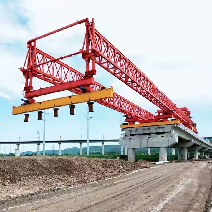
Pictures & Components
I. Main Structural Framework
This is the primary skeleton of the machine, providing support and stability.
Main Gantry (Primary Girder/Truss):
Function: The main overhead bridge-like structure that spans the entire width of the piers and the gap between them. It carries the entire load of the segments and the lifting system.
Description: Typically a large, box-type or truss-type steel structure. It must be incredibly rigid to resist bending and torsion during operations.
Front Support Leg (Nose/Landing Leg):
Function: Provides support on the pier ahead, transferring the load forward as the bridge is extended. It often "walks" or is repositioned to the next pier.
Description: A telescopic or fixed leg with a hydraulic system for fine adjustment and locking onto the pier cap.
Rear Support Leg (Main Support Leg):
Function: Anchors the machine to the already constructed part of the bridge. It carries a significant portion of the machine's weight and the counterweight moment.
Description: A robust leg assembly that clamps securely onto the bridge deck or pier.
Central Support Leg (Intermediate Leg - if applicable):
Function: Used on longer machines to provide additional support and reduce stress on the main girder. It may rest on a pier or a temporary tower.
II. Segment Handling and Erection System
This is the core system that picks up, moves, and positions the concrete segments.
Main Hoist (Lifting Winches/Trolleys):
Function: To lift the pre-cast segments from the transport vehicle (at the rear) and carry them to the front for placement.
Description: Consists of powerful electric or hydraulic winches with high-strength steel cables. The hoists are mounted on trolleys that run along rails on the bottom of the main gantry.
Lifting Frames (Spreader Beams):
Function: To distribute the lifting force evenly across the segment to prevent damage. They connect the hoist cables to the lifting points on the segment.
Description: Rigid steel frames with multiple pickup points. They can often rotate and adjust to handle different segment types or curves.
III. Propulsion and Movement System
This system allows the entire machine to "walk" forward onto the next span.
Propulsion System (Walking Mechanism):
Function: To move the entire machine forward to the next construction position after a span is completed.
Description: Typically uses hydraulic cylinders or walking pads that push against the bridge deck. The machine moves in a "inchworm" or "walking" motion, alternating between lifting, pushing, and setting down.
Support Leg Hydraulics:
Function: To raise, lower, and precisely position the support legs during the launching cycle. This includes retracting the front leg to clear obstacles and extending it to land on the next pier.
IV. The Counterweight System
This is a critical safety and operational component, especially for a balanced cantilever erection method.
Counterweight Deck/Area:
Function: A designated structural area at the rear of the machine where counterweights are placed.
Counterweight Blocks:
Function: To balance the overturning moment created by the cantilevered segments being placed at the front of the machine. This keeps the machine stable and prevents it from tipping over.
Description: These are often massive, pre-cast concrete blocks or steel weights. The total counterweight is carefully calculated based on the weight of the segments and the length of the cantilever. For a 120-ton machine, the counterweight could be in the range of 60-100 tons, depending on the design.
V. Auxiliary and Control Systems
These systems bring everything together and allow for precise operation.
Hydraulic Power Unit (HPU):
Function: Provides pressurized hydraulic fluid to all hydraulic components (cylinders for legs, propulsion, and some hoists).
Description: A central unit with pumps, reservoirs, filters, and cooling systems.
Electrical Control System:
Function: The "brain" of the machine. It controls and synchronizes all movements of the hoists, trolleys, and propulsion system.
Description: Includes a central control cabin with PLCs (Programmable Logic Controllers), joysticks, and monitoring screens.
Safety and Monitoring Systems:
Function: To ensure safe operation.
Components:
Load Moment Indicators (LMIs): Monitor the load on the hoists and the stability of the machine.
Anemometer: Measures wind speed; operations are halted if winds exceed safe limits.
Limit Switches: Prevent components from moving beyond their safe range.
Redundant Braking Systems: On all hoists and trolleys.
Segment Alignment System (Temporary Post-Tensioning):
Function: While not a part of the machine itself, the BEM works in conjunction with a system to hold segments in place before the permanent tendons are stressed.
Description: This includes temporary epoxy resin applied between segments and temporary steel bars or strands that pull the new segment against the previous one.

Sketch


Advantages
Key Advantages of a 120-Ton Counterweight Bridge Erecting Machine
1. Enhanced Stability and Safety
This is the most significant advantage. The 120-ton counterweight actively balances the machine during its most critical operation: when it is reaching out to place a new segment, creating a large overturning moment.
Prevents Toppling: The heavy counterweight generates a stabilizing moment that counteracts the moment created by the weight of the segment being lifted and the machine's own boom. This is crucial for safety.
Operates in "Unbalanced" Conditions: It can safely erect segments on one side of the pier (for balanced cantilever construction) without the need for a temporary "back span" or ground-based supports.
2. Ability to Span Long Distances
The stability provided by the counterweight allows the machine to have a long reach.
Long Cantilevers: It can place segments far from the supporting pier, enabling the construction of bridges with long spans (typically 100-200 meters, depending on the design) without intermediate piers.
Ideal for Challenging Terrain: This makes it perfect for crossing obstacles like rivers, highways, gorges, and environmentally sensitive areas where building intermediate piers is difficult, expensive, or impossible.
3. Minimal Ground Footprint and Disruption
Since the machine is supported entirely by the bridge structure itself, it has a very small impact on the ground below.
No Ground Disruption: There is no need for extensive temporary works, foundations, or falsework on the ground. This is a major advantage in ecologically sensitive areas or over active transportation routes (railways, highways, navigable waterways).
Traffic Can Flow Uninterrupted: Construction can proceed above a highway or railway without the need for closures or significant traffic disruptions.
4. High Precision and Control
These machines are engineered for precision. They feature sophisticated hydraulic and electronic control systems.
Micrometer-Level Adjustment: They can precisely maneuver heavy segments (weighing up to 120 tons in this case) in all directions (up/down, left/right, pitch, yaw) to ensure a perfect fit with the previously placed segment.
Ensures Bridge Geometry: This precision is critical for maintaining the correct bridge alignment, profile, and ensuring the segments' shear keys and epoxy joints fit perfectly, which is vital for the structural integrity of the finished bridge.
5. Efficiency and Speed of Construction
The process is highly methodical and repetitive, leading to fast construction cycles.
Cycle Time: Once the machine is set up, the cycle of lifting, transporting, positioning, and stressing a segment can be completed in a matter of hours. A typical cycle can be as short as 3-7 days per segment pair (one on each side).
Parallel Operations: While the machine is erecting segments at the front, other crews can work on the completed deck behind it (e.g., on barrier walls, drainage, and pavement), speeding up the overall project timeline.
6. Versatility and Adaptability
A 120-ton capacity machine is a robust and versatile model.
Handles Heavy Segments: The 120-ton capacity allows it to handle large, heavy segments, which can reduce the total number of segments needed for a span and speed up construction.
Adaptable to Complex Geometries: Many modern machines can be configured to erect bridges with complex geometries, including horizontal and vertical curves.
Adjustable Counterweight: The counterweight is often not a fixed mass; it can be adjusted (e.g., by adding or removing weight blocks or adjusting its position) to optimize balance for different segment weights and reach distances.
7. Improved Economic Viability for Specific Projects
While the machine itself is a significant capital investment, its advantages often lead to lower overall project costs in the right scenarios.
Reduced Temporary Works: The savings from eliminating massive falsework and ground support structures can be enormous.
Faster Completion: Reduced construction time leads to lower overhead costs and earlier return on investment, especially for projects with high traffic or economic impact.

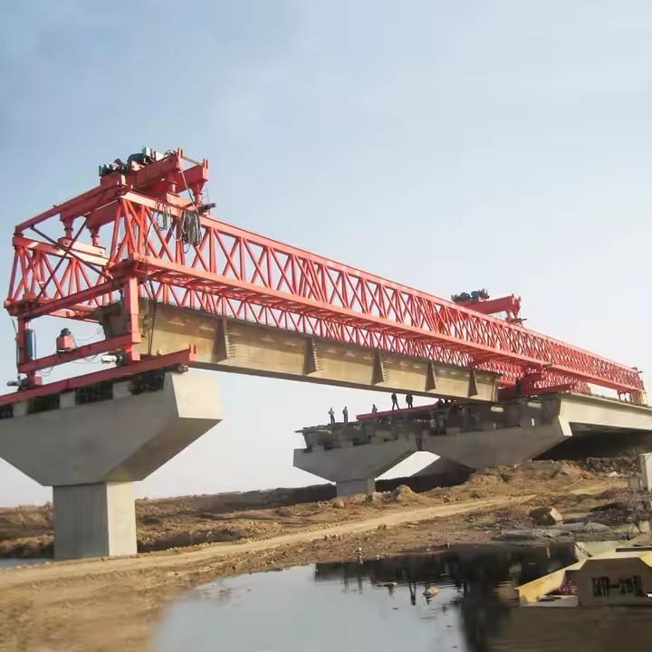
Application
Core Application and Working Principle
The primary application is the Balanced Cantilever Construction Method. This method is used when building over deep valleys, wide rivers, gorges, or existing roads/railways where scaffolding from the ground is impossible or prohibitively expensive.
How it Works:
The machine is positioned on top of the already constructed pier. It then proceeds to build the bridge deck symmetrically in both directions from the pier, one segment at a time.
Positioning: The machine is assembled on the pier.
Casting/Lifting: A new 120-ton (or less) segment of the bridge deck is either:
Cast-in-Place: Concrete is poured into a formwork attached directly to the machine.
Pre-cast: A pre-fabricated segment is delivered and lifted into place by the machine.
Stressing: High-strength steel tendons (cables) are threaded through the segment and tensioned, locking it securely to the previous segments.
"Walking" Forward: Once the segment is secured, the entire machine uses a hydraulic system to "walk" or "launch" itself forward onto the newly built deck to prepare for the next segment.
Counterweight Role: Throughout this process, the machine is holding significant weight at its front end (the new segment and its own front gantry). To prevent the machine from tipping over backwards, a counterweight is applied at its rear. This counterweight, often in the form of concrete blocks or a water tank, creates a balancing moment, ensuring stability.
Key Applications and Project Scenarios
This machine is indispensable in the following scenarios:
Long-Span Viaducts: Crossing wide valleys or floodplains.
River Crossings: Building over major rivers where ship traffic cannot be interrupted for falsework.
Mountainous Terrain: Constructing bridges across deep gorges.
Urban Infrastructure: Erecting flyovers or bridge extensions over existing highways and railways without disrupting traffic below.
Cable-Stayed Bridge Pylons: Building the deck that connects to the base of the cable-stayed bridge towers.

Production Procedure
Production Procedure for a 120-Ton Counterweight Bridge Erecting Machine
1. Project Definition & Planning Phase
1.1. Design Review & Finalization:
A comprehensive review of all engineering drawings, calculations, and specifications is conducted by a team of engineers, production managers, and quality control.
Key components include the main beam (girder), support legs (front and rear), lifting hoists, trolley, hydraulic system, electrical control system, and the counterweight system.
All design codes (e.g., AISC, EN, GB) and safety factors are verified.
1.2. Material Procurement & Inspection:
Raw Materials: Procurement of high-strength steel plates (e.g., Q345B, Q460C or equivalent ASTM A572 Gr. 50), structural sections (I-beams, channels), and steel castings/forgings for critical parts.
Purchased Components: Sourcing of certified components including hydraulic cylinders, pumps, valves, electric motors, frequency converters, brakes, wire ropes, pulleys, bearings, and electrical cabinets.
Incoming Inspection: All materials and purchased components are inspected against purchase orders and relevant standards. Material Certificates (Mill Certificates) are verified.
1.3. Production Planning:
Creation of a detailed production schedule, Work Order, and Bill of Materials (BOM).
Allocation of resources: manpower, workshop space, welding stations, and heavy-duty machining centers.
2. Fabrication & Manufacturing Phase
2.1. Steel Cutting & Profiling:
Steel plates and sections are marked according to nesting drawings.
Cutting is performed using CNC plasma/oxy-fuel cutting machines or high-precision saws to ensure dimensional accuracy and clean edges.
Drilling of bolt holes is done using CNC drilling machines or magnetic base drills for precision.
2.2. Sub-Assembly Fabrication:
Main Box Girders: Steel plates are welded to form the large, box-section main beams. This is a critical process.
Jigging & Fit-up: Components are placed in a large, rigid assembly jig to prevent distortion and ensure correct geometry.
Welding: Performed by certified welders using Submerged Arc Welding (SAW) for long seams and Shielded Metal Arc Welding (SMAW) or Gas Metal Arc Welding (GMAW) for other joints. Pre-heating and post-weld heat treatment (PWHT) may be required for thick plates to relieve stresses.
Support Legs & Towers: Fabricated similarly, with precise machining of mating surfaces and pin connection holes.
Trolley Frame: The structure that carries the hoist is fabricated, ensuring flatness and squareness for smooth travel.
Counterweight Containers/Frames: Fabricated to safely hold the specified counterweight blocks (often concrete or steel).
2.3. Machining of Critical Components:
Key connection points, such as the pins for leg articulation, hinge points, and trolley rail surfaces, are machined on large boring mills, lathes, or planers to achieve the required tolerances and surface finish.
3. Assembly & Integration Phase
3.1. Pre-Assembly (Fit-up):
Major sub-assemblies (main beams, legs) are brought together in the assembly area.
A preliminary "dry" fit-up is performed without final welding or bolting to verify dimensions and alignment. Pin connections are checked for free movement.
3.2. Main Structural Assembly:
The main box girders are connected (bolted or welded as per design) to form the full-span structure.
Support legs and towers are attached to the main girder using high-strength pins and bolts.
The trolley rails are installed and aligned along the top flange of the main girder.
3.3. Mechanical System Installation:
Trolley and Hoist System: The trolley is placed on the rails. The main lifting hoist(s) (120-ton capacity, typically a double-winch system with wire ropes) is installed on the trolley.
Travel System: Wheels or crawlers for the machine's longitudinal movement are installed on the support legs.
Hydraulic System: Hydraulic cylinders (for leg adjustment, fine positioning), power pack, hoses, and valves are installed and connected.
3.4. Electrical & Control System Installation:
Power Distribution: Main electrical cabinet, cable reels, and power cables are installed.
Control System: Programmable Logic Controller (PLC), frequency converters for motor control, sensors (limit switches, load cells, encoders), and the operator's cabin with control pendants are installed and wired.
Safety Systems: Emergency stop circuits, overload protection, anti-collision sensors, and warning alarms are integrated.
4. Testing & Commissioning Phase (Factory Acceptance Test - FAT)
This is a critical phase to ensure the machine functions as designed before disassembly for shipment.
4.1. Dimensional Inspection:
Verify overall dimensions, alignment of main girder, and parallelism of rails.
4.2. Non-Destructive Testing (NDT):
Ultrasonic Testing (UT) or Radiographic Testing (RT) on critical weld joints.
Magnetic Particle Testing (MT) or Dye Penetrant Testing (PT) on machined surfaces and pin holes.
4.3. Load Testing (As per relevant standards - e.g., FEM, DIN, GB):
Static Load Test: The machine is anchored, and the hoist is used to lift a test load of 125% of the Safe Working Load (SWL). For a 120-ton machine, this is 150 tons. The load is held for a specified time (e.g., 10-15 minutes) while inspectors check for deflection, permanent deformation, and integrity of welds and structures.
Dynamic Load Test: The hoist is used to lift and move a test load of 110% of SWL (132 tons). The trolley travels the full length of the girder, and the hoist performs lifting and lowering cycles. This test verifies the performance of motors, brakes, and control systems under dynamic conditions.
4.4. Functional & Safety Tests:
Test all movements: hoisting, lowering, trolley travel, and gantry travel.
Verify all limit switches, emergency stops, and overload protection systems.
Test hydraulic system for leaks and pressure holding.
Calibrate load cells and other sensors.
5. Preparation for Shipment
5.1. Marking & Dismantling:
All components are marked with unique identifiers corresponding to assembly drawings.
The machine is systematically dismantled into shipable modules, considering weight and size constraints for transport.
5.2. Surface Protection & Packaging:
All structural steel surfaces are shot-blasted to Sa 2.5 standard and painted with a protective coating system (primer, intermediate, and topcoat).
Machined surfaces and hydraulic cylinder rods are coated with anti-corrosive grease and protected with plywood or plastic covers.
Hydraulic and electrical components are sealed and packaged to prevent moisture and dust ingress during transit.
5.3. Documentation Packing:
A comprehensive set of documents is prepared, including:
As-built drawings
Design calculations
Welding procedure specifications (WPS) and records (PQR)
NDT reports
Material certificates
Load test certificates
Operation and Maintenance Manual
Parts catalog
Hydraulic and Electrical schematics
6. Site Erection & Commissioning (Provided by Manufacturer's Engineers)
Once the components arrive on the bridge construction site, the manufacturer's engineers typically supervise the re-erection and final commissioning, including a final load test on the actual bridge before commencing erection work.


Workshop View
The company has installed an intelligent equipment management platform, and has installed 310 sets (sets) of handling and welding robots. After the completion of the plan, there will be more than 500 sets (sets), and the equipment networking rate will reach 95%. 32 welding lines have been put into use, 50 are planned to be installed, and the automation rate of the entire product line has reached 85%.


Hot Tags: 120ton counterweight bridge erecting machine, China 120ton counterweight bridge erecting machine manufacturers, suppliers, factory
You Might Also Like


Send Inquiry