


Self-balancing Bridge Erecting Machine For Bridge Construction manufacturers

Self-balancing Bridge Erecting Machine For Bridge Construction suppliers

Self-balancing Bridge Erecting Machine For Bridge Construction factory

Self-balancing Bridge Erecting Machine For Bridge Construction best
Self-balancing Bridge Erecting Machine For Bridge Construction high quality
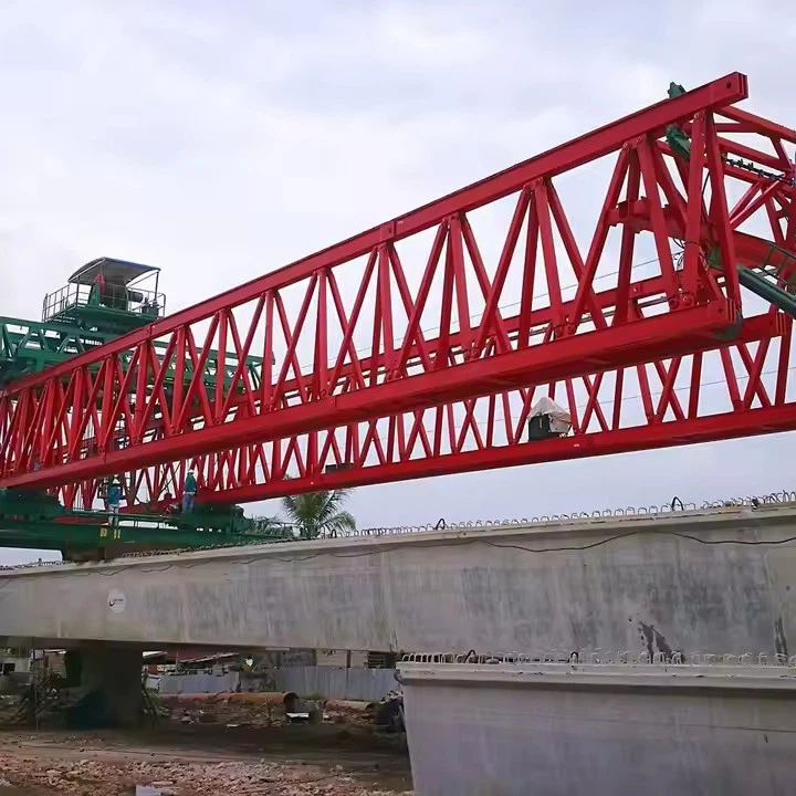
Self-balancing Bridge Erecting Machine For Bridge Construction
A 190 T Bridge Launcher is a self-propelled, movable gantry system used to lift and place pre-cast concrete segments or steel girders for constructing viaducts, overpasses, and other elevated highway or railway structures. The "T" stands for "Tonne" (metric ton), indicating its lifting capacity, but the "190" is the span length in meters.

How It Works: The Step-by-Step Process
The principle is similar to a seesaw. Imagine the machine anchored to a completed pier.
The "Seesaw" Analogy:
Fulcrum: The main support of the machine on the pier.
Load Arm: The front part of the machine that extends over the gap, carrying the new segment to be installed.
Counterweight Arm: The rear part of the machine that extends back over the already-completed bridge deck, carrying heavy counterweights.
The Process:
The machine moves a new segment to the front (load arm).
This action creates a massive overturning moment, trying to tip the entire machine forward into the valley.
To counteract this, the counterweights at the rear (counterweight arm) generate an equal and opposite moment.
The Formula: (Weight of Segment × Distance from Fulcrum) ≈ (Weight of Counterweight × Distance from Fulcrum)
This equilibrium keeps the machine stable and the pier safe from excessive bending stresses.
The Role of Hydraulics and Control Systems: Sophisticated computer-controlled hydraulic jacks constantly make micro-adjustments to the counterweights or the support legs to maintain perfect balance throughout the lifting and placing process. Strain gauges and inclinometers provide real-time feedback.
Specification
Applicable Standards: Design and manufacturing shall conform to, but not be limited to, the latest editions of:
FEM 1.001 (Rules for the Design of Hoisting Appliances)
DIN 15018 (Cranes; Steel Structures; Principles for Design and Construction)
AISC 360 (Specification for Structural Steel Buildings)
AWS D1.1/D1.5 (Structural Welding Code)
Relevant local and national safety codes.
Design Life: The main structure shall be designed for a minimum of 10,000 working hours or 20 km of bridge construction.
Working Environment:
Ambient Temperature: -20°C to +50°C
Maximum Wind Speed:
Operational: 15 m/s
Survival (non-operational, parked): 36 m/s
Relative Humidity: Up to 95% non-condensing.

Pictures & Components
Key Components
The machine can be broken down into several major subsystems:
1. Main Gantry Structure:
Primary Beams/Girders: These are the two massive, longitudinal steel trusses or box girders that form the backbone of the machine. They span the distance between the front and rear supports and carry the entire load.
Cross Beams: These connect the two primary beams, providing lateral stability and forming a rigid frame.
2. Support and Leg Systems (The "Feet"):
Front Support Legs: These are located at the leading end of the machine. They are equipped with hydraulically controlled clamps or shoes that grip the top of the newly constructed bridge deck or the front pier.
Rear Support Legs: These are located at the trailing end. They also have clamps and grip the stable, completed section of the bridge deck.
Intermediate Supports (if applicable): Some larger machines may have additional supports for very long spans.
3. Self-Balancing Mechanism (The "Brain" and "Muscles"):
Hydraulic Cylinders: These are the core of the balancing act. They are located at the support legs and allow for:
Vertical Adjustment: To compensate for deck slope, camber, or settlement.
Load Transfer: To shift the machine's weight between the front and rear supports during the launching cycle.
Computer Control System & Sensors: This is the "brain." It continuously monitors:
Load Cells: Measure the weight on each leg.
Inclinometers: Measure the tilt of the main girders.
Position Encoders: Track the position of hydraulic cylinders.
The control system automatically adjusts the hydraulic pressure in the cylinders to maintain a level and stable platform, ensuring no single support is overloaded.
4. Lifting and Handling System:
Hoist/Crane: A traveling hoist (or multiple hoists) runs along rails on the main girders. It is used to lift the pre-cast segments from the transport vehicles at the rear of the machine and carry them forward to their installation position.
Spreader Beams: Attached to the hoist, these ensure that the large, heavy segments are lifted evenly without being damaged.
5. Propulsion System (The "Movement"):
Launching Mechanism: This is how the machine moves itself forward. It typically uses a walking or sliding mechanism:
Hydraulic Jacks/Walking Pads: The machine "walks" by sequentially lifting its legs, shifting its weight, and pushing itself forward on sliding shoes. This is a step-by-step process controlled by the central system.
6. Auxiliary Systems:
Power Pack: A diesel generator or an electrical connection that provides power for the hydraulics, controls, and lighting.
Safety Systems: Emergency stops, anti-collision systems, wind speed monitors, and overload protection.
Work Platforms: Provide safe access for workers along the length of the machine.

Sketch


Advantages
Key Advantages of Self-Balancing Machines
The advantages stem directly from the core principle of maintaining equilibrium during construction.
1. Enhanced Safety
This is the most critical advantage.
Elimination of Overturning Risk: Traditional methods often involve building out from a pier in one direction (unbalanced cantilever), creating a huge overturning moment that must be resisted by the pier or temporary props. The self-balancing method cancels out these moments, making the process inherently stable.
Reduced Risk of Structural Failure: By keeping the pier in a near-zero moment condition during construction, the risk of overstressing the permanent structure is minimized.
Safer Work Environment: The stable platform provides a safer and more predictable environment for workers assembling the segments.
2. Increased Construction Speed and Efficiency
Simultaneous Construction: The machine can place segments on both sides of a pier in a single cycle, effectively doubling the progress rate compared to sequential methods.
Continuous Workflow: The balanced approach allows for a more rhythmic and continuous workflow, reducing idle time. There's no need to wait for one side to be stabilized before starting the other.
Faster Cycle Times: Without the need to assemble and disassemble large temporary supports or counterweights, the overall project timeline is significantly shortened.
3. Superior Structural Integrity and Quality
Controlled Deformation: The balanced construction minimizes deflections and creep effects in the concrete during the construction phase. This results in a final bridge profile that is much closer to the theoretical design, leading to a smoother riding surface.
Reduced Cracking: By avoiding large, unbalanced temporary stresses, the risk of micro-cracking in the concrete segments and the pier is greatly reduced.
Precise Alignment: The machines are highly automated, allowing for millimeter-level precision in segment placement, ensuring the bridge is built exactly to its designed alignment and geometry.
4. Economic Advantages
Reduced Need for Temporary Works: This is a massive cost saving. Traditional balanced cantilever construction often requires expensive temporary piers, falsework, or large counterweights. The self-balancing machine integrates this function, eliminating or drastically reducing these costs.
Lower Labor Costs: The process is more mechanized and requires fewer personnel for erecting temporary structures.
Faster Project Completion: Time is money. A shorter construction period leads to lower overhead costs, earlier opening for revenue (in the case of toll bridges), and reduced disruption-related costs.
5. Versatility and Adaptability
Suitable for Challenging Sites: These machines are ideal for constructing bridges over deep valleys, wide rivers, busy highways, or ecologically sensitive areas where erecting temporary supports from the ground is impractical, dangerous, or prohibitively expensive.
Ability to Navigate Complex Geometries: Advanced models can be used to construct bridges with complex horizontal and vertical curves.
6. Reduced Environmental and Social Impact
Minimal Ground Disturbance: Since most of the work happens from the deck level, there is minimal disruption to the terrain, waterways, or ecosystems below.
Less Disruption to Existing Traffic: When building over a road or railway, the need for closures or protective scaffolding is reduced, as the work is largely self-contained above.

Application
Primary Applications in Bridge Construction
This machine is not a one-size-fits-all solution but is exceptionally effective in specific scenarios:
Precast Segmental Balanced Cantilever Construction: This is the most classic application. The machine places pairs of segments symmetrically on either side of a pier, perfectly utilizing its self-balancing nature to maintain equilibrium during the entire "cantilevering" process.
Span-by-Span Construction with Precast Segments: The machine assembles an entire span (from one pier to the next) on the ground or at the ends of the bridge, lifts the whole span, and places it onto the piers. The self-balancing is crucial during the lifting and launching phase.
Launching of Full-Span Prefabricated Box Girders: For medium-span bridges, entire bridge spans (e.g., 40-50 meters) can be prefabricated and then launched into place by these machines. The self-balancing feature is vital when the girder is cantilevering out during the launching process.
Construction in Challenging Environments:
Over Deep Valleys or Rivers: Eliminates the need for expensive, difficult, and environmentally disruptive falsework from the ground or water.
Over Existing Traffic (Rail or Road): Allows construction to proceed with minimal disruption to the traffic below, as the machine works from above.
In Ecologically Sensitive Areas: Minimizes ground disturbance and impact on the landscape.

Production Procedure
Core Principle of "Self-Balancing"
Before the procedure, it's crucial to understand the "self-balancing" mechanism. The machine does not rely on external supports from the ground. Instead, it uses a combination of:
Rear Anchorage: It is firmly anchored to the already constructed deck behind it.
Nose Support: The front (nose) of the machine rests temporarily on the next pier, often on a sliding bearing or a temporary saddle.
Hydraulic System: A sophisticated system of hydraulic jacks and winches moves the machine forward in a controlled, balanced manner, ensuring the center of gravity always remains over the supported structure.
Production Procedure: Step-by-Step
The entire process is a repetitive cycle for each new span. We'll assume the machine is already assembled on the bridge abutment or first few piers.
Stage 1: Preparation for a New Cycle
Machine Positioning & Stabilization:
The machine is positioned over the pier where the last segment was placed. Its main legs are securely clamped to the completed deck segments.
The front nose of the machine is supported on the next pier (the "target pier") via a temporary bearing.
All structural connections are verified for integrity.
Segment Transportation & Feeding:
Pre-cast concrete or steel bridge segments are manufactured off-site and transported to the launch site.
Segments are brought to the rear of the machine using a transport vehicle (e.g., a multi-wheeled trailer).
The machine's internal hoisting system (a lifting trolley that runs along the main girder) picks up the segment and moves it into position under the machine's main frame. Segments are typically stored temporarily within the machine's span.
Stage 2: Segment Lifting and Placement
Lifting the Segment:
The lifting trolley moves to the segment's storage position, lowers its hooks, and securely attaches to the segment's lifting anchors.
The segment is lifted to the required height, slightly above its final position.
Fine Positioning:
The trolley transports the segment forward along the main girder to its precise placement location at the front of the machine.
Using precision hydraulic controls (and often guided by a GPS or Total Station system), the segment is meticulously aligned both vertically and horizontally.
Temporary Stressing:
Once positioned, the new segment is temporarily connected to the previously placed segment using post-tensioning (PT) steel bars or tendons.
This temporary stressing holds the segments together, forming a cantilever, and allows the machine to transfer its weight onto the new segment for the next launch cycle.
Stage 3: Post-Tensioning and Joint Completion
Epoxy Application (for Concrete Segments):
Just before placing the segment, a thin layer of high-strength epoxy is applied to the matching face of the previous segment. This epoxy ensures a full bearing surface and waterproofs the joint.
Permanent Post-Tensioning:
After several segments are placed (often in a symmetrical pattern to maintain balance, e.g., one on each side), the permanent post-tensioning tendons are threaded through the ducts in the segments.
The tendons are stressed (tensioned) using hydraulic jacks to a specified force, compressing the entire span and giving it its structural strength. This is typically done after a full span or a balanced pair of segments is completed.
Stage 4: The Self-Balancing Launch Forward
This is the most critical and characteristic phase of the operation.
Anchorage Transfer:
The rear leg clamps are released. The machine's weight is now supported by its front nose on the target pier and the main legs on the deck behind it.
The rear anchorage system is disengaged and prepared for the next cycle.
Launching Sequence:
Main Girder Advance: The main girders of the machine are pushed forward over the newly constructed span. This is done using large hydraulic cylinders that push against the stable part of the deck.
Nose Support Adjustment: The front nose support is adjusted to guide the girders and ensure a smooth transition onto the next pier.
Continuous Balance Monitoring: Throughout this process, the hydraulic system and control software continuously adjust pressures and movements to keep the machine's center of gravity within safe limits, preventing tipping.
Re-anchoring and Re-stabilization:
Once the main girders have advanced the full length of one span, the rear legs are lowered and securely clamped onto the deck.
The front nose is positioned and secured on the next pier (the new "target pier").
The machine is now stable and ready to begin the cycle again for the next span (return to Stage 1).


Workshop View
The company has installed an intelligent equipment management platform, and has installed 310 sets (sets) of handling and welding robots. After the completion of the plan, there will be more than 500 sets (sets), and the equipment networking rate will reach 95%. 32 welding lines have been put into use, 50 are planned to be installed, and the automation rate of the entire product line has reached 85%.


Hot Tags: self-balancing bridge erecting machine for bridge construction, China self-balancing bridge erecting machine for bridge construction manufacturers, suppliers, factory
You Might Also Like


Send Inquiry