


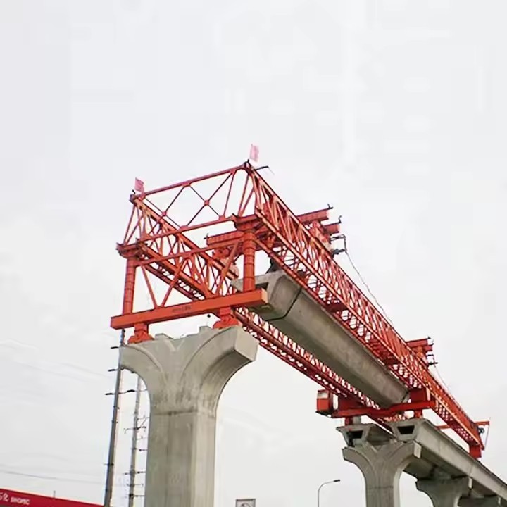

Truss Bridge Erection Machine
In essence, it's any heavy-duty machine or system designed to lift, position, and assemble the large, pre-fabricated segments (members) of a truss bridge into their final place.

How It Works: The Step-by-Step Process
How It Works: The Step-by-Step Process
The process is cyclical, repeating for each new segment of the bridge. The machine is typically assembled on the first few piers at one end of the bridge.
Step 1: Delivery and Pick-Up
A new truss segment, prefabricated in a yard and transported to the site, is positioned underneath the erection machine. The machine's powerful lifting hoists lower their hooks, attach to the segment, and lift it off the transport vehicle. The vehicle then leaves.
Step 2: Lifting and Shifting
Once lifted clear, the hoists raise the segment to the required height. The traversal system then shifts the entire segment forward along the gantry rails until it is hanging directly behind the previously installed segment at the front of the bridge.
Step 3: Advancing the Segment (The Critical Move)
The hoists carefully move the new segment forward, cantilevering it out from the gantry. The front "nose" of the gantry provides a temporary resting point for the leading edge of the new segment. The segment is precisely aligned with the existing bridge structure.
Step 4: Connecting the Segment
Work crews (connectors and bolters) safely access the connection points. They physically connect the new segment to the previous one using high-strength bolts or welds. This permanently integrates the new segment into the bridge structure.
Step 5: Preparing to Move Forward (Indexing)
Once the segment is secure, the machine must "walk" forward to prepare for the next cycle.
The rear support legs are retracted and lifted.
The entire gantry structure is propelled forward on its bogies along the top of the new bridge deck it just helped build.
Once the rear legs have passed the previous pier, they are lowered and securely anchored to the new pier behind them.
The front legs are then retracted, and the gantry moves further forward until the front legs are positioned on the next pier ahead. The front legs are then lowered and anchored.
Step 6: Repeat
The machine is now in its starting position, ready to receive the next truss segment. The cycle repeats until the entire bridge is complete.

Pictures & Components
1. Main Structural Framework
This is the primary skeleton of the machine that bears all the loads.
Main Gantry/Gantry Frame: The primary steel bridge-like structure that spans the gap between piers. It is typically a box girder or truss structure itself, providing the rigidity and strength to handle the weight of the bridge segments.
Front Support (Nose): An extensible cantilevered section at the front of the gantry. It provides support for the bridge segment before it is positioned and helps guide the machine to the next pier.
Legs/Support Towers: Vertical or inclined columns that transfer the load from the gantry down to the bridge pier or the deck. They are often adjustable in height.
Front Legs: Mount on the new pier being approached.
Rear Legs: Mount on the already constructed part of the bridge deck or on a previous pier.
Base/Bogie: The foot of each support leg, which often contains a clamping mechanism to securely grip the pier or deck.
2. Hoisting and Handling System
This system is responsible for the actual lifting and moving of the truss segments.
Main Hoist (Lifting Winches): High-capacity electric or hydraulic winches with redundant braking systems. They are rated to lift the immense weight of the truss segments.
Lifting Beams/Spreader Frames: A specialized lifting device that connects the winch cables to the truss segment. It is designed to distribute the lifting force evenly across multiple pick-up points on the segment to prevent bending or damage.
Trolley/Carriage: The unit that houses the winches and moves along rails on the top or bottom flange of the main gantry, allowing the segment to be moved longitudinally into position.
Auxiliary Hoist: A smaller, secondary winch used for handling tools, temporary platforms, or for assisting in the rotation and fine adjustment of segments.
3. Propulsion System (Self-Launching Mechanism)
This is what allows the massive machine to move itself forward as the bridge is constructed.
Propulsion Winches/Crawlers: These are typically two types:
Winch and Cable System: A winch is anchored to a fixed point ahead on the deck or pier. The machine pulls itself along a set of rails by winding in the cable.
Self-Propelled Crawlers: Hydraulic crawler tracks (similar to those on an excavator but much larger) mounted on the support legs or the main gantry. They provide a powerful and controlled "walking" motion.
Guidance Rails/Tracks: Heavy-duty rails installed on the top or sides of the bridge deck or piers. The machine's bogies or crawlers run on these tracks to ensure perfect alignment during movement.
4. Hydraulic and Control Systems
The "muscles" and "brains" of the operation.
Hydraulic Power Unit (HPU): A large diesel or electric-powered unit that generates high-pressure hydraulic fluid for all functions: leg adjustment, clamping, propulsion, and sometimes hoisting.
Synchronous Control System: The most critical safety system. A computer-controlled system that ensures all winches and propulsion drives operate in perfect sync. It prevents one winch from lifting faster than another, which could tilt a segment dangerously.
Operator Cabin: A climate-controlled cabin with panoramic views, equipped with joysticks, control panels, and monitors displaying load weights, pressures, and alignment data.
Sensors and Instrumentation: Includes:
Load Cells: To measure the weight on each hoist.
Inclinometers: To monitor the level of the gantry and the segment.
Laser Guidance Systems: To ensure precise positioning of the segment relative to the previous one.
Position Encoders: To track the movement of the trolley and the machine itself.
5. Auxiliary and Safety Components
Clamping Systems: Hydraulic clamps on the support legs that lock the machine securely to the piers or deck, preventing any movement during lifting operations.
Jacking Systems: Hydraulic jacks integrated into the legs for fine adjustment of the gantry's height and leveling.
Work Platforms and Access Ladders: Provide safe access for workers to all parts of the machine for maintenance and connection work.
Anchoring Systems: Temporary tie-downs and anchors used to secure the machine during high winds or when it is not in operation.
Emergency Systems: Redundant brakes (mechanical, hydraulic, and electric), backup power, and emergency stop buttons throughout the machine.

Sketch


Advantages
1. Enhanced Safety
This is the most critical advantage.
Minimized Work-at-Height Risks: The machine provides a stable, enclosed platform for workers to assemble bridge segments at ground level or in a controlled factory setting. This drastically reduces the need for personnel to work at great heights over rivers, valleys, or roads.
Reduced Ground Crew Exposure: Much of the assembly and pushing (launching) operation is controlled remotely by a small team, minimizing the number of workers in potentially hazardous zones under the moving structure.
Stability and Control: The machines are engineered for exceptional stability during the launching process, with synchronized hydraulic systems that control the precise movement of the heavy bridge structure, preventing tipping or slippage.
2. Superior Efficiency and Speed of Construction
Parallel Workflows: While the machine launches the completed truss sections forward, the next sections can be assembled simultaneously on the back end of the machine. This assembly-line process significantly accelerates the project timeline.
Continuous Operation: The launching process is largely independent of weather conditions like high winds (within limits) that would ground crane operations for days.
Rapid Cycle Times: Once set up, the machine can launch a new section in a matter of hours, allowing for rapid progression across the span.
3. Economic Advantages
Reduced Labor Costs: While the machine itself is a major capital investment, it requires a smaller crew to operate compared to the large teams needed for extensive falsework or multiple crane setups.
Minimized Falsework: In situations over deep gorges, busy highways, or navigable waterways, building temporary support towers (falsework) is incredibly expensive, logistically complex, and sometimes impossible. The launching gantry eliminates or drastically reduces this need.
Lower Rental Costs: For long bridges, using a dedicated launching gantry is often more economical than renting multiple ultra-high-capacity cranes for an extended period.
Predictable Scheduling: The methodical nature of the process leads to more predictable construction schedules, reducing the risk of costly delays.
4. Access and Environmental Advantages
Construction in Inaccessible Terrain: This method is ideal for crossing obstacles where access for cranes or construction vehicles is severely limited, such as mountainous regions, protected wetlands, or wide rivers.
Minimal Ground Disturbance: Since most work is done from the top of the piers or from the already constructed bridge deck, there is very little disturbance to the ground below. This is a major benefit in environmentally sensitive areas.
Minimal Disruption to Existing Traffic: When building over active railways, highways, or waterways, the machine can operate with minimal clearance, often without the need to completely shut down the traffic below. The work happens above the obstruction.
5. High Precision and Quality
Controlled Assembly Environment: Truss segments are typically welded or bolted together in a fixed, stable location at the rear of the machine. This allows for higher quality control than field assembly in unpredictable conditions.
Accurate Alignment: The machine guides the new truss segment into perfect alignment with the previously launched section, ensuring the entire bridge deck is constructed to precise geometric tolerances.
6. Versatility and Adaptability
Modern erection machines are highly adaptable and can be used for:
Various Span Lengths: They can be configured for different truss lengths and weights.
Complex Geometries: They can handle straight, curved, or even slightly inclined bridge alignments.
Different Bridge Types: While ideal for truss bridges, the same launching principle is used for box girder and segmental bridges.

Application
Application of a Truss Bridge Erection Machine
The primary application of a truss bridge erection machine is to efficiently, safely, and precisely assemble the large, heavy structural components of a truss bridge at the project site, often in challenging environments like deep gorges, wide rivers, or existing transportation corridors.
These machines are essential for modern bridge construction, enabling projects that would be otherwise too dangerous, time-consuming, or disruptive using traditional methods like large cranes.
1. Primary Applications and Use Cases
Truss erection machines are specifically designed for the following scenarios:
Launching Bridges Over Obstacles: Their most critical use is building bridges over obstacles where it is impossible or prohibitively expensive to build temporary support scaffolding (falsework). This includes:
Deep Valleys and Gorges: Building support towers in the bottom of a ravine is impractical.
Navigable Waterways: Building in-water falsework would block ship traffic and is susceptible to currents and floods.
Busy Highways or Rail Lines: Construction cannot disrupt the constant flow of traffic below.
Balanced Cantilever Construction: The machine allows the bridge to be built outward from both sides of a pier simultaneously. This method keeps the structure balanced, minimizing the bending forces on the pier during construction.
Segmental Construction: Truss bridges are often built in segments. The machine is used to lift, position, and secure these pre-fabricated segments (which can include deck sections, truss members, or entire truss panels) in their precise final location.
Push Launching (Incremental Launching): While more common for box girder bridges, some specialized machines can be used to "push" completed truss sections outward from the abutment as new sections are assembled behind them.

Production Procedure
Production Procedure: Truss Bridge Erection Machine
1.0 Definition and Purpose
A Truss Bridge Erection Machine (often called a Launching Gantry or Erection Gantry) is a large, self-supporting steel structure used to lift, position, and assemble prefabricated truss bridge segments. It eliminates the need for extensive falsework and ground-based cranes, making it ideal for erecting bridges over deep valleys, water bodies, busy roads, or environmentally sensitive areas.
2.0 Key Components of the Machine
Before detailing the procedure, it's crucial to understand the main components:
Main Gantry Frame: The primary steel structure that spans the bridge piers.
Lifting Nose / Launching Nose: A lighter, cantilevered section attached to the front to guide the machine during launching.
Support Legs / Towers: Adjustable legs that transfer the machine's weight to the bridge piers or deck.
Lifting Hoists (Winches & Cables): The powered system (electric or hydraulic) that lifts and moves the truss segments.
Launching System: A mechanism (typically hydraulic jacks or winches) to move the entire gantry forward to the next position.
Control System: The electrical and hydraulic control cabin for operating all functions.
Walkways & Safety Systems: Platforms, guardrails, and emergency stop systems.
3.0 Phase 1: Design and Engineering
Project Requirements Analysis:
Review bridge design (truss type, segment weight and dimensions, span lengths, curvature).
Analyze site conditions (geography, weather, wind loads, seismic factors, access).
Determine maximum lifting capacity, required span, and lifting height.
Conceptual & Detailed Design:
Create structural calculations and Finite Element Analysis (FEA) models to ensure strength, stability, and deflection control under all load cases (lifting, launching, wind).
Design mechanical systems (winches, jacks, pulleys), hydraulic systems (cylinders, pumps), and electrical control systems.
Develop detailed fabrication drawings, assembly diagrams, and Bill of Materials (BOM).
Regulatory Compliance & Certification:
Ensure the design complies with all relevant safety standards and codes (e.g., EN 13001, ASME B30, local regulations).
Engage a third-party certifying authority to review and approve the design.
4.0 Phase 2: Manufacturing and Fabrication
This phase occurs in a controlled workshop environment.
Material Procurement:
Source high-grade steel (e.g., S355, ASTM A572) according to the BOM.
Procure certified mechanical components (winches, wire ropes, hooks), hydraulic components (pumps, valves, cylinders), and electrical components (motors, sensors, PLCs).
Steel Fabrication:
Cutting: Steel plates and sections are cut to size using CNC plasma/oxy-fuel cutters or saws.
Drilling & Machining: Holes are drilled for bolts; surfaces are machined for perfect fit-up.
Bending: Specific members are bent to required radii using plate bending rolls or press brakes.
Welding: Components are assembled into sub-assemblies (e.g., girders, towers, legs) using primarily Submerged Arc Welding (SAW) for high-quality, automated welds. All critical welds are Non-Destructively Tested (NDT) via Ultrasonic Testing (UT) or Magnetic Particle Inspection (MPI).
Abrasive Blasting & Painting: Fabricated parts are blasted to Sa 2.5 standard to remove mill scale and rust, then painted with a protective coating system (primer, intermediate, and top coat) for corrosion protection.
Sub-Assembly:
Weld smaller components into larger modules (e.g., a full leg assembly with hydraulic cylinders).
Pre-assemble mechanical and hydraulic systems onto the steel modules where possible.
Factory Acceptance Test (FAT):
Assemble the entire gantry or major subsystems at the factory yard if space permits.
Test all functions: hoist lifting (with test load), leg raising/lowering, gantry traversal, and control systems.
Perform load testing (typically 125% of rated capacity) to verify structural integrity and safety.
Certify all lifting equipment and calibrate load monitoring systems.
5.0 Phase 3: Transportation and Site Assembly
Dismantling & Packaging:
The machine is logically dismantled into transportable modules, considering road weight and size restrictions.
Components are carefully tagged for easy identification on-site.
Transportation to Site:
Modules are shipped via flatbed trucks, barges, or rail to the bridge construction site.
Site Preparation:
Prepare a level and stable assembly area, often on the ground at one end of the bridge (the "launching platform").
Pour concrete foundations if required for the initial assembly.
Assembly on Site:
Use mobile cranes to assemble the main components in the correct sequence.
Typical Sequence: Assemble support legs on the first piers -> Erect the main gantry frame on top of the legs -> Attach the lifting nose -> Install winches, hydraulic systems, and electrical cabinets -> Connect all power and control lines -> Perform functional checks.
6.0 Phase 4: Erection Procedure (In-Service Operation)
This is the cyclic process of building the bridge.
Positioning for First Segment:
The gantry is positioned over the first pier pair. Legs are securely locked.
Lifting and Placing Truss Segments:
A prefabricated truss segment is delivered by trailer to under the gantry.
The gantry's hoists lower their hooks/slings, which are connected to the segment.
The segment is lifted, moved transversely (if needed), and precisely positioned onto the temporary supports or previous segment.
Workers connect and bolt or weld the segment in place.
Launching (Advancing the Gantry):
Once a complete span or a stable section is built, the gantry prepares to move forward.
The process is highly methodical:
a. Secure Back: The rear legs are locked to the completed bridge deck.
b. Release Front: The front legs are retracted and lifted.
c. Advance: Using the launching system (e.g., hydraulic jacks pushing on skids), the entire gantry is moved forward along the deck until the front legs reach the next pier.
d. Re-Support: The front legs are lowered and securely anchored to the new pier.
e. Re-Set: The rear legs are released and the gantry is shifted fully onto the new supports. The cycle is now ready to repeat.
Cycle Repeat:
The process of Lift -> Place -> Launch is repeated until the entire bridge is erected.
7.0 Phase 5: Dismantling and Demobilization
Final Position Dismantling:
Once the final bridge segment is placed, the gantry is positioned at the far end of the bridge.
The process is reversed: it is dismantled using cranes into modules small enough for transport.
Load-Out and Shipment:
Modules are loaded onto trucks and shipped to the next project or storage facility.


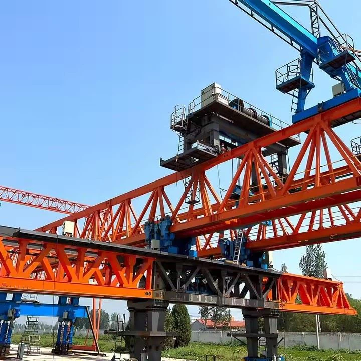
Workshop View
The company has installed an intelligent equipment management platform, and has installed 310 sets (sets) of handling and welding robots. After the completion of the plan, there will be more than 500 sets (sets), and the equipment networking rate will reach 95%. 32 welding lines have been put into use, 50 are planned to be installed, and the automation rate of the entire product line has reached 85%.


Hot Tags: truss bridge erection machine, China truss bridge erection machine manufacturers, suppliers, factory
You Might Also Like


Send Inquiry