










80 Ton Rail Mounted Gantry Crane
Products Description
An 80-ton RMG is a massive, electrically-powered gantry crane that runs on fixed ground rails, typically used for moving shipping containers in intermodal terminals, port yards, and logistics hubs.
1. Core Technical Specifications
Lifting Capacity: 80 metric tons (approx. 176,000 lbs). This is the safe working load (SWL), typically measured under the spreader. This capacity allows it to handle all standard and most heavy-weight ISO containers, including 20', 40', 45', high-cube, and reefer containers, often in twin-lift (two 20ft) or even tandem-lift mode.
Span: Wide span (e.g., 25 to 50 meters) to cover multiple container rows (typically 6+1 or 7+1 truck lanes) and rail tracks within its portal.
Lifting Height: High hoisting height to stack containers 5-over-1 or 6-over-1 (5 or 6 containers high, with a 7th on the ground), maximizing yard density.
Rail Gauge: The distance between the two main ground rails. This is a fixed parameter designed for the specific terminal layout.
2. Structural & Mechanical Features
Box-Girder Design: The main girder(s) are constructed from high-strength steel in a box-section design, providing immense rigidity and strength to handle the dynamic loads while minimizing sway.
High-Performance Hoist & Trolley: Equipped with precise, variable-frequency drives for smooth acceleration, deceleration, and positioning of the spreader. The trolley travels along the main girder(s).
Automated Spreader: A Twistlock spreader is standard, often with capabilities for:
Auto-sliding: To handle containers of different lengths (20ft, 40ft, 45ft) automatically.
Weighing System: Integrated load cells to weigh containers during handling.
Scanner Systems: OCR (Optical Character Recognition) cameras to automatically identify container numbers and ISO codes.
Robust End Carriages & Bogies: The legs run on heavy-duty rail wheels (bogies) designed to distribute the enormous weight and ensure smooth travel along the runway rails.
3. Control & Automation (A Key Modern Feature)
Operator Cab Control: Traditional control from an air-conditioned cab mounted on the crane, offering the operator a panoramic view of the working area.
Radio Remote Control: Allows an operator to control the crane from the ground, offering flexibility and a better view for precise container spotting.
Full Automation (ASC - Automated Stacking Crane): This is the most advanced feature for modern terminals. The RMG can operate:
Autonomously via a Terminal Operating System (TOS).
Using Pre-set Stacking Programs.
Guided by laser positioning systems (LiDAR), GPS, and anti-sway systems for pinpoint accuracy without human intervention.
4. Safety Systems
Anti-Collision System: Prevents collisions with other RMGs working on the same rail track or with obstacles in the yard.
Anti-Sway System: Automatically controls and minimizes container swing during trolley travel and gantry movement for safety and efficiency.
Wind Speed Indicator & Alarm: Automatically alarms and stops crane operations if wind speeds exceed safe limits.
Twistlock Verification: Sensors confirm that the container is securely locked onto the spreader before lifting and fully unlocked after placement.
Emergency Stop Buttons: Located at multiple points on the crane and on remote controls.
End-Buffer & Limiter Switches: Prevents the crane from over-traveling at the ends of the runway rails.
5. Power & Energy Efficiency
Electrically Powered: Typically connected to the terminal's grid via a cable reel or busbar/collector system running the length of the rail.
Regenerative Drives: A critical feature. The hoist motor acts as a generator when lowering a container, feeding energy back into the grid or for use by other systems, reducing net energy consumption by up to 30-40%.
Energy Storage Systems: Some modern RMGs are equipped with super-capacitors or battery banks to store regenerated energy for peak power demands.
6. Operational & Economic Advantages
High Stacking Density: Enables very dense stacking of containers, optimizing valuable terminal space.
Improved Yard Organization: Allows for better segregation of import, export, empty, and reefer containers.
High Handling Rates: Capable of achieving 25-35 moves per hour (gross cycle time), making it one of the most productive yard solutions.
Reduced Carbon Footprint: Electric power produces zero local emissions, especially beneficial compared to diesel-powered Rubber-Tyred Gantry (RTG) cranes.
Lower Operational Costs: Electricity is cheaper than diesel, and regenerative braking further cuts costs. Maintenance is generally lower than on RTGs due to fewer moving parts and no engines or tyres.
Comparison: Rail Mounted vs. Rubber-Tired Gantry (RTG) Cranes
| Feature | Rail Mounted Gantry (RMG) | Rubber-Tired Gantry (RTG) |
|---|---|---|
| Mobility | Fixed rails, straight path | Moves freely on paved ground |
| Load Capacity | 10–500+ tons | 5–100 tons |
| Precision | High (guided movement) | Moderate (manual steering) |
| Stability | Excellent (wind-resistant) | Less stable in high winds |
| Automation | Easily automated | Limited automation |
| Maintenance | Lower (rails reduce wear) | Higher (tire replacements) |
| Cost | Higher initial investment | Lower upfront cost |
Best For:
RMG → Heavy-duty, high-precision, long-term operations (ports, steel plants).
RTG → Flexible, short-term projects needing mobility.
Lifting Capacity: 30 metric tons (30,000 kg)
Span: 10m–35m (customizable)
Lifting Height: 6m–20m (adjustable)
Hoist Type: Double-girder with electric wire rope hoist (QD-type)
Travel System: Motorized (rail-guided or rubber-tired)
Wheel Type: Steel wheels (for rails) / Pneumatic tires (floor use)
Control System: Cabin-operated or remote control
Power Supply: 380V/50Hz (3-phase)
Structural Steel: Q345B (high-strength) with corrosion-resistant coating

Pictures & Components
An 80-ton RMG is a massive, self-contained lifting machine that runs on fixed rails, typically in container terminals, intermodal yards, and heavy industrial settings. Its primary function is to lift, move, and stack containers and other heavy loads with precision.
The components can be categorized into several major systems:
1. Structural System (The Frame & Support)
This is the physical skeleton of the RMG that bears all the loads.
Main Gantry (Bridge Girder): The primary horizontal beam that spans the width of the working area (e.g., the container stacks and truck/rail lanes). It is typically a large, welded steel box girder designed for immense strength and minimal deflection (sagging).
Legs (End Carriages): The vertical structures at each end of the main girder that support it and house the drive mechanisms. They are designed to withstand high vertical and horizontal forces.
Landside Leg: The leg on the side of the crane where ground traffic (trucks, terminal tractors) operates. It often has a different shape to provide clearance for this traffic.
Waterside Leg: The leg on the side facing the container stacks. Its design is optimized for maximum stacking reach and height.
Crane Rails and Runway: While not part of the crane itself, the fixed rails and their supporting concrete foundation are critical components. The entire RMG travels on these rails. The 80-ton rating is dependent on a properly engineered and maintained runway.

2. Hoisting System (The Lifting Mechanism)
This system is responsible for the actual lifting and lowering of the load.
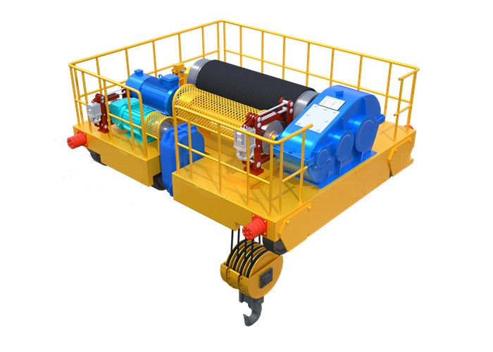
Trolley: The assembly that travels along the length of the main girder (the crane's "width" axis). It carries the hoisting machinery.
Hoist Motor: A high-power electric motor that provides the torque to raise and lower the load. It is typically an AC or DC motor with variable frequency drives for smooth and precise control.
Wire Ropes & Sheaves: High-strength steel wire ropes that are spooled on the drum and routed through a system of pulleys (sheaves) to multiply the lifting force and connect to the spreader.
Drum Unit: A large, cylindrical steel drum around which the wire ropes are wound and stored.
Brakes: Multiple, redundant fail-safe brakes are used, including:
Main Hoist Brake: A disc or caliper brake that holds the load.
Emergency Brake / Safety Brake: A secondary, mechanical brake that engages automatically in case of a power failure or if the main brake fails.
 |
 |
3. Spreader (The Load Handling Device)
The specialized attachment that connects to the container.
Twistlock Mechanism: Hydraulically or electrically operated locking pins (twistlocks) that engage into the corner castings of a standard shipping container to secure it.
Spreader Frame: The rigid structure that houses the twistlocks. It can often be adjusted hydraulically to handle different container lengths (e.g., 20ft, 40ft, 45ft) and sometimes different widths.
Guidance System: A system of cameras and/or laser sensors that helps the operator align the spreader accurately over a container.
 |
 |
4. Drive and Travel System (The Mobility)
This system allows the entire crane and the trolley to move.
Gantry Travel Drives: The motors, gearboxes, and wheels that propel the entire RMG structure along the ground rails. There are multiple drives (one on each leg) that must be synchronized.
Trolley Travel Drives: The motor and gearbox system that moves the trolley back and forth along the main girder.
Wheels and Bogies: Sets of wheels (arranged in bogies for load distribution) that the crane and trolley run on. Made from high-grade forged steel.

5. Power System (The Energy Source)
How the crane receives its electrical power.
Cable Reel System: A large motorized drum that pays out and retracts a heavy-duty electric cable as the crane moves. This cable is connected to a power source along the runway.
Alternative: Conductor Bar (Bus Bar) System. Instead of a cable, the crane collects power from rigid electrified bars running parallel to the rails using sliding collectors (shoes). This is more common for large, modern RMGs due to higher reliability and less maintenance.
Step-Down Transformers & Switchgear: Located on the crane itself, this equipment takes the high-voltage incoming power (e.g., 480V or 6.6kV) and converts it to usable voltages for the motors, control systems, and lighting.

6. Control and Operator Cabin
The nerve center for crane operation.
Operator's Cabin: Usually mounted on the trolley, giving the operator a full view of the spreader and the stacking area. It is climate-controlled and sound-proofed.
Control Consoles: Joysticks, switches, and touchscreens that the operator uses to control all crane functions: hoisting, trolley travel, gantry travel, and spreader functions.
Programmable Logic Controller (PLC): The industrial computer that acts as the crane's brain. It processes operator commands, manages motor drives, monitors safety systems, and prevents unsafe operations.

7. Safety Systems
Critical components that protect personnel, the load, and the crane itself.
Anti-Collision System: Sensors (LiDAR, radar) to prevent the RMG from colliding with other cranes, buildings, or obstacles in its path.
Anemometer & Wind Speed Indicator: Measures wind speed and automatically issues warnings or shuts down crane operations if limits are exceeded.
Limit Switches: Prevents the trolley or hoist from moving beyond its intended physical limits (end-of-rail and maximum height).
Load Moment Indicator (LMI): A computer that calculates the load weight and the crane's stability in real-time, preventing overload conditions.
Emergency Stop (E-Stop) Buttons: Strategically placed red buttons to halt all crane motion immediately.
Anti-Sway System: An automated control system that uses the trolley and hoist motions to dampen the natural pendulum swing of the suspended load.
.
Technical Specifications Example
| Parameter | Typical Range |
|---|---|
| Capacity | 10-500 metric tons |
| Span | 10-50 meters |
| Lifting Height | 6-30 meters |
| Travel Speed | 5-40 m/min (VFD controlled) |
| Hoisting Speed | 0.5-10 m/min (dual-speed) |
| Work Duty | FEM 2m-3m (heavy duty) |
| Power Supply | 380V/415V 50Hz 3-phase |

This comprehensive component system ensures reliable operation in demanding environments like:
Stone slab handling facilities
Port container terminals
Heavy fabrication shops
Steel mill service areas

SKETCH

Main technical

Advantages
1. Operational and Productivity Advantages
High Handling Capacity & Speed: RMGs are designed for rapid, continuous cycling of containers. They can stack containers quickly and move them efficiently between trucks, trains, and storage blocks, significantly increasing the terminal's overall throughput.
Dense Stacking: One of the biggest advantages. An 80-ton RMG can typically stack containers 5-6 wide and 5-6 high (often "over 6 on 1"). This dramatically increases storage density within a limited yard footprint, which is crucial for land-constrained ports.
Wide Span: The crane's gantry spans the entire container storage block, the access road for trucks, and often multiple rail tracks. This allows it to service all these areas without needing to move out of the way, creating a highly integrated workflow.
Dual-Lift Capability (for some models): Many modern 80-ton RMGs are equipped with a twin-lift spreader, allowing them to pick up two 20-foot containers or one 40/45-foot container simultaneously. This nearly doubles productivity for certain operations.
2. Economic Advantages
Low Operating Cost (OPEX): RMGs are almost always electrically powered from a conductor bar system (like a tram or train). This is far more energy-efficient and cheaper than diesel-powered alternatives like Rubber-Tired Gantries (RTGs). Electricity costs are lower and more stable than diesel fuel.
Reduced Labor Requirements: A single operator can run the entire stacking and retrieval process from a cabin on the crane. Furthermore, automated or semi-automated RMG systems can reduce the need for multiple ground personnel like checkers and shunt truck drivers.
High Reliability & Low Maintenance: Running on fixed, precision rails causes far less wear and tear on the crane's structure and wheels compared to RTGs that run on uneven asphalt. This leads to lower long-term maintenance costs and higher availability (uptime).
Land Utilization: By enabling very high stacking, an RMG system reduces the need for expensive land acquisition. You can store more containers in the same area, maximizing the return on investment for the terminal property.
3. Environmental and Safety Advantages
Zero Local Emissions: Being electric, RMGs produce no exhaust emissions (like NOx, SOx, or particulate matter) at the point of use. This is a major advantage for ports located near urban areas and for complying with increasingly strict environmental regulations.
Low Noise Pollution: Electric operation is significantly quieter than diesel-powered equipment, reducing the noise impact on surrounding communities.
Enhanced Safety: The fixed rail system provides a predictable movement path, separating crane operations from other terminal traffic. Furthermore, operators have a superior, elevated view of the entire work area from the cabin, reducing the risk of accidents.
Stability and Resilience: The robust rail foundation makes RMGs highly stable and less susceptible to weather conditions like high winds compared to taller, wheeled cranes.
4. Automation and Technological Advantages
Ideal for Automation: The fixed and predictable operating environment of an RMG (running on rails with precise positioning systems) makes it the ideal candidate for full automation. Automated RMGs (ARMG) can operate 24/7 with minimal human intervention, leading to massive gains in efficiency and consistency.
Precision and Integration: They integrate seamlessly with terminal operating systems (TOS) and can be equipped with advanced optical character recognition (OCR) systems to identify containers automatically, GPS for positioning, and collision avoidance systems.
Application:
An 80-ton Rail Mounted Gantry (RMG) crane is a heavy-duty, electrically powered gantry crane that runs on fixed rails. It is a cornerstone of modern intermodal freight and heavy material handling operations, designed for precision, efficiency, and high-volume lifting.
Primary Applications
The 80-ton capacity places this RMG in a category for handling very heavy loads, defining its key applications:
1. Intermodal Freight Terminals (Container Yards)
This is the most common application. The 80-ton RMG is the workhorse of container terminals, rail terminals, and port staging areas.
Stacking Containers: Its primary job is to stack shipping containers (20ft, 40ft, 45ft, high-cube) in dense, high-bay configurations (often 5-6 containers wide and 4-5+ high). An 80-ton capacity is crucial as a loaded 40ft container can weigh up to ~30.5 tons, and the crane must handle them safely, often with a spreader that adds its own weight.
Loading/Unloading Rail Cars (Wagon Loading): RMGs efficiently transfer containers between stack yards and flatbed rail cars (well cars). The crane spans multiple rail tracks and container stacks, allowing it to service an entire train without needing to reposition it.
Loading/Unloading Trucks: It serves truck gates, lifting containers directly onto or off of chassis (skeletal trailers) for road transport.
2. Heavy Industrial Manufacturing and Fabrication
Handling Large Components: In industries like shipbuilding, wind energy, and heavy machinery manufacturing, 80-ton RMGs are used to move large, prefabricated sections, engines, turbines, and other massive components.
Production Line Feeding: They can shuttle heavy materials between different stages of a production process, especially in large, sprawling fabrication halls or outdoor yards.
3. Logistics and Storage Hubs for Heavy Goods
Steel and Paper Industries: Used for handling heavy coils of steel, rolls of paper, and other dense, bulky materials that are stored in large yards and need to be loaded onto outbound transportation.
Breakbulk Cargo: While less common than for containers, they can be configured with hooks or specialized grabs to handle breakbulk cargo like lumber, machinery, or large crates.
Crane production procedure
Phase 1: Project Planning & Design Engineering
Objective: To define all technical specifications, create manufacturing drawings, and plan the production process.
Contract Review & Technical Specification Finalization:
Confirm customer requirements: lifting capacity (80-ton + perhaps a test load factor), span, lifting height, duty class (e.g., FEM 1B, A4), operating speed, power supply, and environmental conditions.
Finalize the technical specification document signed by both the customer and manufacturer.
Conceptual & Detailed Design:
Structural Design: Use Finite Element Analysis (FEA) software (e.g., ANSYS, SolidWorks Simulation) to design the main structural components:
Main Girders: The primary horizontal beams that form the bridge.
End Carriages: The structures at each end of the girders that house the wheels, motors, and drive systems. They must be designed to withstand rail misalignment and wind loads.
Mechanical Design: Design the hoisting mechanism (winch, wire rope, hook block), trolley travel mechanism, and gantry travel mechanism. Select standard components like motors, brakes, gearboxes, bearings, and wire ropes based on calculated loads.
Electrical & Control System Design: Design the power distribution system, variable frequency drives (VFDs) for smooth operation, and the control system (usually PLC-based). Plan for safety systems (emergency stop, limit switches, anti-collision, anemometer for wind speed).
Creation of Manufacturing Drawings: Produce detailed part drawings, assembly drawings, and Bill of Materials (BOM) for all components.
Procurement Planning:
Identify long-lead items (main motors, drives, PLC, special steel sections) and initiate procurement.
Phase 2: Procurement & Material Preparation
Objective: To source all raw materials and purchased components.
Raw Material Procurement:
Purchase steel plates, profiles (I-beams, channels), and hollow sections as per the BOM and cutting plans. Material certificates must be obtained to verify grade (e.g., S355JR) and quality.
Purchased Components Procurement:
Order all mechanical and electrical components: motors, gearboxes, brakes, wheels, bearings, wire ropes, hooks, VFDs, PLCs, cabling, operator cabin, etc.
Material Preparation:
Shot Blasting: Clean and descale all steel plates and sections to remove rust and mill scale.
Priming: Apply a primer coat of paint to prevent corrosion during fabrication.
Cutting & Profiling: Use CNC plasma/oxy-fuel cutting machines to cut steel plates to the required sizes and shapes based on the nested cutting drawings.
Phase 3: Fabrication & Machining
Objective: To manufacture the main structural components to precise dimensions.
Fabrication of Main Girders:
Weld the cut plates into box girders or truss structures on large, flat fabrication beds using submerged arc welding (SAW) for long seams and MAG welding for other joints.
Use strongbacks and jigs to prevent welding distortion.
Perform intermediate non-destructive testing (NDT) like Ultrasonic Testing (UT) or Magnetic Particle Inspection (MPI) on critical welds.
Fabrication of End Carriages:
Fabricate the rigid frame that will house the wheels and travel motors.
Machine the mounting pads for the wheel assemblies and drive units to ensure perfect alignment.
Fabrication of Trolley Frame:
Fabricate the robust frame that will carry the hoisting unit and travel along the main girders.
Machining of Critical Components:
Machine key interfaces, such as the end carriage mating surfaces and wheel bearing housings, on large boring mills and lathes to achieve high precision.
Phase 4: Sub-Assembly & Surface Treatment
Objective: To build smaller modules before final assembly.
Sub-Assemblies:
Assemble the wheel groups for the end carriages and the gantry travel drive units.
Assemble the trolley, mounting the hoist motor, gearbox, drum, and sheaves onto the trolley frame.
Assemble the operator's cabin with all controls and displays.
Dimensional Inspection:
Check all sub-assemblies for dimensional accuracy and alignment.
Surface Treatment & Painting:
Perform any final grinding and surface preparation.
Apply the complete paint system (epoxy primer, build coats, and polyurethane topcoat) as per specification, often to a C4 or C5 corrosion protection standard.
Phase 5: Final Assembly (Erection)
Objective: To assemble all components into the complete crane. This is often done at the manufacturer's yard for testing before disassembly for shipment.
Erection of Runway Rails:
Note: This is typically the customer's responsibility but must be verified by the crane manufacturer.
The crane rails must be installed, aligned, and leveled with extreme precision on a firm foundation.
Assembly of Main Structure:
Place the two end carriages onto the rails.
Lift and connect the main girders to the end carriages using high-strength bolts. Check the squareness and level of the entire bridge.
Mounting of Mechanical Components:
Lift and place the trolley assembly onto the main girder rails.
Connect the long travel drive assemblies to the end carriages.
Electrical Installation:
Run all main power and control cabling along the crane structure using cable trays.
Install the main power panel, VFD cabinets, and PLC cabinet.
Connect all motors, sensors, limit switches, and safety devices.
Install the operator's cabin and connect the control pendants.
Phase 6: Testing & Commissioning
Objective: To verify the crane's performance, safety, and compliance with all design and regulatory standards.
Pre-Functional Checks:
Visual inspection of all components and connections.
Insulation resistance and continuity tests on electrical systems.
Check lubrication of all gearboxes and bearings.
No-Load Tests:
Operate all crane functions (hoist, trolley travel, gantry travel) without load to check for smooth operation, correct direction of movement, and functionality of limit switches.
Static Load Test:
Lift a test load of 125% of the Rated Capacity (100 tons) and hold it at a safe height for a period (e.g., 10 minutes).
Measure the deflection of the main girders (should be within design limits, e.g., < Span/1000).
Inspect the structure for any permanent deformation or cracks.
Dynamic Load Test:
Perform all operational functions with a test load of 110% of the Rated Capacity (88 tons).
Test the functionality of all safety devices under load: emergency stop, overload limit switch, over-winding limit switches, and rail end buffers.
Final Inspection & Documentation:
A third-party inspection agency may be present to witness tests and certify the crane.
Prepare and deliver the complete documentation package (drawings, manuals, test reports, certificates).
Phase 7: Dismantling, Packaging & Shipment
Objective: To prepare the crane for transport to the customer's site.
Marking & Dismantling: Carefully mark all components and connections before disassembling the crane into transportable modules (girders, end carriages, trolley, etc.).
Packaging: Protect machined surfaces and electrical components from damage during transit. Use wooden crates and waterproof wrapping.
Shipment: Load onto trucks or flatcars following a pre-defined shipping plan.
Phase 8: Site Installation & Final Commissioning
Objective: To reassemble and commission the crane on the customer's premises.
Site Erection: The manufacturer's erection team reassembles the crane on the customer's prepared runway using mobile cranes.
Re-commissioning: Repeat essential functional and load tests on-site to ensure everything was reassembled correctly and the crane operates perfectly in its final location.
Customer Training: Train the customer's operators and maintenance personnel on the safe and efficient use of the crane.
Handover: Formal handover of the crane to the customer after successful site acceptance tests.


Workshop view
Material Inspection
Quality Inspection: Strict quality inspection is carried out on the purchased raw materials to ensure that they meet the design requirements and national standards.
Material Storage: Qualified materials are stored according to classification to prevent corrosion or damage.
Cutting and Forming
Steel Cutting: Use plasma cutting, laser cutting or flame cutting and other technologies to cut the steel according to the size of the design drawing.
Forming Processing: Form the steel plate through bending, rolling, welding and other processes to manufacture the main beam, end beam and other structural parts.
Welding
Component Welding: The cut and formed steel parts are welded into the main structures such as the main beam, end beam and trolley. The welding process needs to be strictly controlled to ensure the structural strength and welding quality.
Weld Inspection: Use non-destructive testing technology (such as ultrasonic testing, radiographic testing) to inspect the welds to ensure that there are no cracks or other defects.
Machining
Precision Machining: Precision machining is performed on the key components of the crane, such as wheel sets, bearing seats, pulleys, etc., to ensure their dimensional accuracy and surface quality.
Assembly of the whole machine
General assembly: On the basis of pre-assembly, the overall assembly of the crane is carried out, including the final installation of the main beam, end beam, lifting mechanism, walking mechanism, etc.
Commissioning and testing
Under dynamic conditions, the operating performance of the crane is tested, including the testing of lifting, walking, steering and other functions. The overall size of the assembled bridge crane is checked to ensure that all dimensions meet the design requirements.
Spraying and anti-corrosion treatment
Surface treatment Rust removal: Rust removal on the surface of the crane, common methods include sandblasting, pickling, etc. Primer spraying: Spray anti-corrosion primer on the treated surface to prevent metal oxidation and corrosion. Topcoat spraying Color spraying: Spray topcoat according to customer requirements or industry standards to give the crane a protective and decorative effect. Marking: After spraying, mark the crane's identification information in accordance with the specifications, such as model, rated load, etc.
Factory and installation
Packaging and transportation
Packaging protection: Protectively package the key components of the crane to prevent damage during transportation. Transportation arrangement: According to the equipment size and transportation conditions, select a suitable transportation method to transport the crane to the customer's site.
Acceptance and delivery
Customer acceptance
On-site acceptance: The customer conducts on-site acceptance of the crane according to the contract requirements and technical specifications to check the performance and quality of the equipment.
Problem rectification: If any problems are found, the manufacturer needs to rectify them in time to ensure that the equipment fully meets the customer's requirements. Delivery and use Operation training: The manufacturer usually trains the customer's operators to ensure that they can operate the crane correctly and safely.


Hot Tags: 80 ton rail mounted gantry crane, China 80 ton rail mounted gantry crane manufacturers, suppliers, factory
You Might Also Like



Send Inquiry