






120T Counterweight Bridge Erecting Machine
Core Features
1. Adjustable Counterweight System
The machine features a rear-mounted counterweight system that balances the forward weight of the lifting trolley, girder, and front gantry. The counterweight can be adjusted by adding or removing weight blocks to optimize balance for different segment weights and reach distances, significantly minimizing the risk of tipping during critical launching phases.
2. High Lifting Capacity and Reach
The 120T rated capacity enables handling of heavy precast girders, making it suitable for large highway, railway, and extra-dosed bridges. The machine is ideally suited for erecting multiple spans of 30 to 60 meters efficiently in sequence.
3. Minimal Ground Disruption
The entire erection process operates from the bridge deck or piers, eliminating the need for ground-level cranes or scaffolding beneath the span. This is particularly advantageous for crossing protected ecosystems, water bodies, active highways, and live railway lines without interrupting traffic or causing ground disturbance.
4. Construction Efficiency and Speed
Once positioned, the machine operates in a fast, repetitive cycle: lift girder, move forward, place, and launch to the next position. This systemization speeds up project timelines and reduces weather dependency compared to methods requiring extensive ground support.
5. Precision Control System
Hydraulic systems allow for millimeter-precise positioning of heavy girders, which is critical for post-tensioned segmental bridges. The machine can handle Pre-stressed Concrete (PSC) I-girders, U-girders, and steel-concrete composite girders.

Key Specifications
| Parameter | Specification |
|---|---|
| Rated Lifting Capacity | 120 tons |
| Adaptable Bridge Span | 30–50 m (customizable) |
| Working Duty | A5–A7 |
| Power Supply | 3-phase AC 380V, 50Hz |
| Lifting Speed | 0.8–1.5 m/min (frequency control) |
| Longitudinal Travel Speed | 0–6 m/min |
| Lateral Travel Speed | 0–3 m/min |
| Adaptable Longitudinal Slope | ≤ 2–5% |
| Minimum Curve Radius | R ≥ 150–350 m |
| Skew Bridge Angle | 0–15° |

Pictures & Components
1. Main Girder Structure (Truss System)
Main Truss Girders - Triangular or trapezoidal truss twin-girder design fabricated from high-strength S355/Q345B steel; forms the primary load-bearing structure
Cross Beams - Connect the twin main girders; provide lateral rigidity and load distribution
Diagonal Bracing - Ensures structural stability and prevents deformation under eccentric loads
Pin Connections - Modular joints allowing on-site assembly and disassembly for transportation
Front Cantilever Section - Extends forward to guide the launching nose during span advancement
2. Counterweight System
Rear Counterweight Frame - Structural steel frame mounted at the rear of the main girder to house counterweight blocks
Counterweight Blocks - Adjustable concrete or steel blocks; total weight configurable to balance the forward lifting moment
Water Tank Counterweight (Optional) - Alternative water-filled tank for easy weight adjustment on site
Counterweight Adjustment Mechanism - Hydraulic or mechanical system for moving counterweight fore/aft to optimize balance
Counterweight Safety Lock - Prevents accidental displacement of counterweight blocks during operation
Load Monitoring Sensors - Detect counterweight position and load distribution in real time
3. Lifting Trolley System
Lifting Trolleys - Independent trolleys travel along the main girders; each equipped with hoisting winch and pulley blocks
Hoisting Winches - Frequency-controlled winches for smooth lifting and precise positioning of girders
Wire Rope & Pulley Blocks - Heavy-duty steel wire ropes with multi-fall pulley systems for 120T rated capacity
Lifting Hooks / Spreaders - Customized lifting beams and hooks designed to safely grip precast girders
Trolley Travel Drive - Motor-driven wheel assemblies enabling longitudinal movement along the main girder
Trolley Lateral Adjustment - Side-shift mechanism for precise girder alignment
4. Leg Assemblies (Support System)
Front Legs (Leading Legs) - Support the front end of the machine; equipped with articulation for curve negotiation
Rear Legs (Trailing Legs) - Support the rear end; include hydraulic adjustment for height variation
Middle Legs (Optional) - Additional support for long-span configurations
Leg Cross Frames - Horizontal bracing between leg columns for lateral stability
Telescopic / Adjustable Legs - Optional hydraulic or mechanical adjustment to accommodate varying pier heights
Leg Travel Bogies - Wheel or rail-mounted bogies at the base of each leg for longitudinal movement
5. Traveling & Steering Mechanism
Longitudinal Travel Bogies - Rail-mounted or trackless bogies that move the entire machine forward/backward
Lateral Travel Bogies - Enable side-to-side movement for precise girder alignment
Steering Cylinders - Hydraulic cylinders for adjusting machine direction on curves
Rail Clamps / Anchors - Secure the machine to the track or ground during lifting operations
Travel Drive Motors - Electric motors with gearboxes driving the bogie wheels
6. Hydraulic System
Hydraulic Power Unit - Central pump station supplying pressurized oil to all hydraulic actuators
Hydraulic Cylinders - Used for leg height adjustment, steering, leveling, and counterweight positioning
Control Valves - Directional, pressure, and flow control valves for precise operation
Oil Tank & Cooler - Reservoir and cooling system maintaining optimal hydraulic fluid temperature
Hydraulic Hoses & Fittings - High-pressure lines connecting the power unit to actuators
Hydraulic Accumulators - Store energy for emergency operations and smooth pressure fluctuations
7. Electrical & Control System
Main Control Cabinet - Houses PLC, contactors, relays, and power distribution components
PLC Control System - Programmable logic controller for automated sequence control and monitoring
Operator Cabin / Remote Control - Ergonomic cabin or wireless remote for machine operation
Variable Frequency Drives (VFDs) - Frequency converters for smooth speed control of winches and travel motors
Sensors & Encoders - Position, load, height, wind speed, and counterweight sensors for real-time feedback
Limit Switches - Prevent over-travel of trolleys, hooks, and legs
Cabling & Cable Reels - Power and signal cables with reeling systems for continuous movement
8. Safety Devices
Overload Limiter - Automatically stops lifting when load exceeds 120T rated capacity
Anti-Tipping Protection - Monitors counterweight balance and machine inclination; alarms or stops operation if stability limits are exceeded
Lifting Height Limiter - Prevents hook over-hoisting
Emergency Stop Buttons - Immediately halts all operations in case of emergency
Wind Speed Anemometer - Alarms and stops operation when wind exceeds safe limits
Anti-Collision System - Prevents collision between trolleys or with end stops
Voltage-Loss Protection - Safely holds load in position during power failure
Rail End Stops - Mechanical stops preventing machine derailment
9. Auxiliary Components
Access Platforms & Walkways - Safe access for maintenance and inspection
Handrails & Safety Gates - Fall protection for personnel
Lighting System - Work lights for night operations
Diesel Generator (Optional) - Standalone power source for remote sites
Tool Kits & Spare Parts - On-site maintenance and repair equipment
Launching Nose - Guide structure for advancing the machine to the next span
Temporary Support Brackets - Used during machine launching and positioning

Sketch
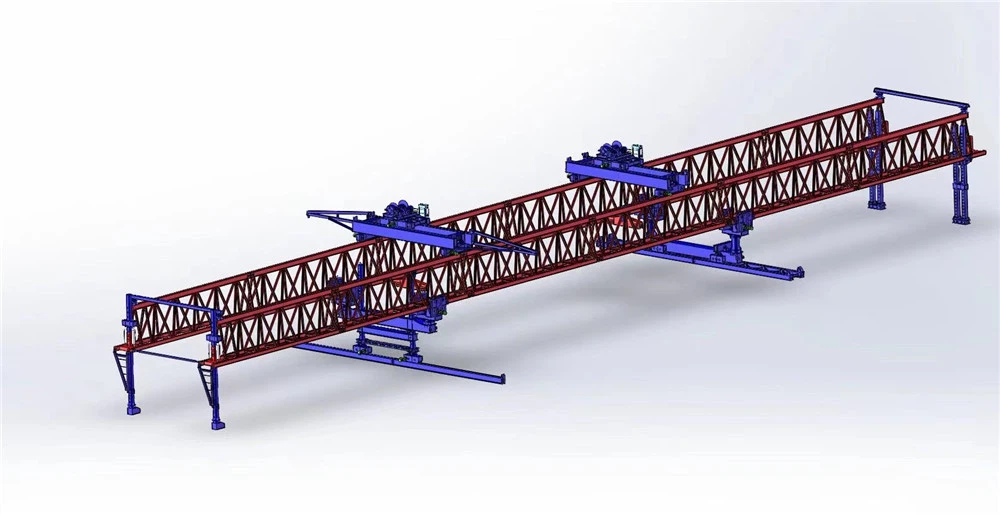

Advantages
1. Superior Lifting Capacity
120-ton rated capacity enables erection of heavier precast girders and larger bridge segments in a single lift
Suitable for long-span highway, railway, and extradosed bridge projects requiring high-capacity lifting
Reduces the number of lifting operations and minimizes risk associated with multiple-piece assembly
Handles Pre-stressed Concrete (PSC) I-girders, U-girders, and steel-concrete composite girders
2. Adjustable Counterweight System
Rear-mounted counterweight balances the forward weight of the lifting trolley, girder, and front gantry
Adjustable weight blocks allow optimization of balance for different segment weights and reach distances
Significantly minimizes tipping risk during critical launching and girder placement phases
Water tank option enables easy on-site weight adjustment without heavy equipment
Hydraulic fore/aft positioning of counterweight provides dynamic balance control during operation
3. Enhanced Stability & Safety
Counterweight system maintains machine stability even when lifting at maximum forward reach
Anti-tipping protection monitors balance and inclination; alarms or stops operation if stability limits are exceeded
Overload limiter automatically stops lifting when load exceeds 120T rated capacity
Wind speed anemometer alarms and halts operation when wind exceeds safe thresholds
Voltage-loss protection safely holds load in position during power failure
Complies with rigorous international safety standards for lifting equipment
4. Minimal Ground Disruption
Entire erection process operates from the bridge deck or piers, eliminating ground-level cranes or scaffolding
Ideal for crossing protected ecosystems, water bodies, active highways, and live railway lines
No interruption to traffic or ground disturbance beneath the span
Reduces environmental impact and permits obtained more easily for sensitive sites
Eliminates need for temporary ground support foundations
5. Excellent Structural Strength
High-strength S355/Q345B steel truss twin-girder design provides optimal strength-to-weight ratio
Triangular or trapezoidal truss configuration ensures excellent torsional rigidity
Modular pin-connected structure maintains structural integrity under eccentric and dynamic loads
Front cantilever section guides launching nose during span advancement
Designed for Working Duty A5–A7 for heavy-duty repetitive operations
6. Precision Control & Synchronization
Advanced PLC control system with real-time monitoring ensures accurate positioning
Dual-trolley synchronous control achieves millimeter-precise positioning, critical for post-tensioned segmental bridges
Variable Frequency Drives (VFDs) provide smooth acceleration, deceleration, and precise speed regulation
Hydraulic systems allow millimeter-precise positioning of heavy girders
Reduces impact loads on both machine and precast girders during lifting
7. Construction Efficiency & Speed
Fast, repetitive cycle: lift girder, move forward, place, and launch to next position
Self-launching capability advances to next span without auxiliary cranes
Systemization speeds up project timelines and reduces weather dependency
Eliminates repeated disassembly and reassembly between spans
Reduces dependence on ground-level crane equipment and site logistics
8. Flexible Adaptability
Adjustable span and height parameters accommodate varying bridge designs
Suitable for straight, curved, and skew bridge erection with skew angles up to 45°
Handles longitudinal slopes up to 5–7% for mountainous or hilly terrain
Adaptable to minimum curve radius of R ≥ 200–400 m
Suitable for balanced cantilever construction, span-by-span erection, and variable-span construction
9. Cost & Time Efficiency
Rapid assembly and disassembly due to modular design reduces mobilization time
Self-launching capability minimizes auxiliary equipment costs
High lifting and travel speeds accelerate project schedules
Reduces labor requirements and overall construction costs per span
Lower foundation and ground improvement costs due to deck-based operation
10. Ease of Operation & Maintenance
Ergonomic operator cabin or wireless remote control for convenient and safe operation
Real-time sensor feedback enables operators to monitor load, position, counterweight status, and machine condition
Access platforms, walkways, and handrails facilitate safe inspection and maintenance
Readily available spare parts and tool kits minimize downtime
Hydraulic accumulators enable emergency operations and smooth pressure fluctuations
11. Environmental & Site Adaptability
Optional diesel generator set enables operation at remote sites without grid power
Corrosion-resistant coating available for harsh environments (coastal, humid, or chemical exposure)
Trackless or rail-mounted options adapt to different site conditions
Low noise and emission configurations available for urban viaduct projects
Deck-based operation minimizes environmental disturbance to ground and water below
12. Wide Application Range
Highway bridge construction - precast box girders, T-beams, and segmental sections
Railway infrastructure - heavy girder erection for rail overpasses and viaducts
Urban viaduct projects - space-constrained urban environments
Balanced cantilever bridges - segmental erection with counterweight balance
Water crossing bridges - erection over rivers, canals, and coastal waters
Industrial and port infrastructure - heavy structural component installation


Application
1. Highway Bridge Construction
Precast Concrete Girder Erection - Lifting and positioning of precast box girders, T-beams, I-beams, and U-beams for highway overpasses and elevated expressways
Long-Span Highway Bridges - 120T capacity enables erection of heavier girders for long-span bridge projects
Multi-Span Bridge Projects - Self-launching capability enables efficient erection across long multi-span highway bridges
Segmental Bridge Construction - Suitable for erecting segmented precast concrete sections in balanced cantilever or span-by-span methods
Highway Interchange & Viaducts - Ideal for complex interchange structures requiring precise girder placement over existing roads
2. Railway Infrastructure
Railway Bridge Erection - Lifting heavy precast girders for railway overpasses, underpasses, and bridge crossings
High-Speed Rail Viaducts - Suitable for erecting precast box girders in high-speed rail elevated sections
Metro & Light Rail Projects - Used in urban rail transit elevated viaduct construction
Railway Station & Yard Bridges - Erection of girders over railway lines with minimal disruption to rail traffic
Electrified Railway Crossings - Deck-based operation avoids interference with overhead catenary systems
3. Urban Viaduct & Elevated Road Projects
Urban Expressway Viaducts - Space-constrained urban environments where ground-level cranes are impractical
City Ring Roads & Elevated Corridors - Efficient erection of precast girders over busy city streets
Pedestrian & Cycle Bridges - Suitable for erecting medium-span pedestrian overpasses and cycle bridges
Urban Rail Transit - Metro elevated lines and light rail viaduct construction
Night Construction in Cities - Lighting system supports around-the-clock erection with minimal traffic disruption
4. Balanced Cantilever & Segmental Bridges
Balanced Cantilever Construction - Counterweight system maintains stability during symmetrical segment erection
Span-by-Span Erection - Efficient repetitive cycle for multi-span segmental bridges
Post-Tensioned Segmental Bridges - Millimeter-precise positioning critical for segment alignment and tendon installation
Extradosed Bridges - Suitable for erecting heavy segments in extradosed bridge construction
Cable-Stayed Bridge Approaches - Erection of approach span girders for cable-stayed bridges
5. Water Crossing Bridges
River Crossing Bridges - Multi-span girder erection over rivers without ground support
Canal & Waterway Crossings - Deck-based operation avoids disturbance to water bodies
Coastal & Estuary Bridges - Suitable for bridge erection over coastal waters and estuaries
Reservoir & Lake Crossings - Erection over water bodies where ground-based cranes are impractical
Protected Ecosystem Crossings - Minimal ground disturbance for environmentally sensitive areas
6. Industrial & Port Infrastructure
Port & Harbor Bridges - Erection of heavy girders for port access bridges and cargo terminal viaducts
Industrial Plant Bridges - Pipe rack bridges, conveyor bridges, and heavy equipment access platforms
Mining & Energy Infrastructure - Bridge erection for mining haul roads, power plant access, and energy facility connections
Logistics & Freight Corridors - Heavy-duty bridge construction for freight rail and truck routes
7. Special Bridge Structures
Curved Bridges - Adaptable to minimum curve radius of R ≥ 200–400 m for curved viaduct erection
Skew Bridges - Handles skew angles up to 45° for non-perpendicular bridge crossings
Sloped Bridges - Operates on longitudinal slopes up to 5–7% for mountainous or hilly terrain
Variable-Span Bridges - Adjustable span parameters accommodate non-uniform bridge designs
First & Last Span Erection - Specialized capability for end-span girder placement
Widening & Retrofit Projects - Suitable for bridge widening and rehabilitation projects

Production Procedure
1. Design & Engineering
Requirements Analysis - Define bridge type, span length, rated capacity (120T), counterweight requirements, and site conditions
Structural Design - Develop truss configuration, main girder dimensions, counterweight frame layout, and load-bearing calculations
Counterweight Balance Calculation - Determine optimal counterweight mass and travel range based on lifting moment and forward reach
Finite Element Analysis (FEA) - Perform stress analysis and structural verification for safety compliance, including stability analysis under counterweight loads
Detailed Drawings - Produce fabrication drawings with precise dimensions, welding specifications, and assembly tolerances
2. Material Preparation
Steel Selection - Procure high-strength structural steel (e.g., Q345B, S355) for main load-bearing components and counterweight frame
Incoming Inspection - Verify material certificates and conduct mechanical property tests
Cutting - Use CNC cutting machines or flame cutting to shape steel plates and sections according to drawings
Edge Preparation - Perform edge trimming, drilling, and beveling for weld joints
3. Fabrication & Welding
Surface Treatment - Remove rust, oil, and contaminants via sandblasting or grinding before welding
Welding Operations - Apply arc welding or gas welding for structural joints; ensure uniform, sound welds
Main Girder Fabrication - Weld truss modules including chords, diagonals, cross beams, and front cantilever section
Counterweight Frame Fabrication - Fabricate rear counterweight frame with mounting points and adjustment mechanism
Quality Control - Inspect weld quality through visual examination and non-destructive testing (NDT)
4. Machining & Component Manufacturing
Precision Machining - Machine pin holes, bolt holes, and connection interfaces for accurate fit
Leg Assembly Fabrication - Manufacture front, middle, and rear leg structures with mounting flanges
Trolley & Winch Assembly - Build lifting trolleys, hoisting winches, and pulley blocks
Bogie Manufacturing - Produce travel bogies with wheels, axles, and drive mechanisms
Counterweight Block Production - Cast or fabricate concrete/steel counterweight blocks with lifting points
Hydraulic Cylinder Manufacturing - Produce or procure hydraulic cylinders for leg adjustment and counterweight positioning
5. Surface Treatment & Painting
Shot Blasting - Clean steel surfaces to Sa2.5 standard for coating adhesion
Primer Application - Apply anti-corrosion primer to all structural components
Topcoat Painting - Apply finish coats with specified color and thickness
Corrosion Protection - Optional hot-dip galvanizing or specialized coatings for harsh environments
Counterweight Coating - Apply protective coating to counterweight blocks for durability
6. Factory Pre-Assembly & Testing
Trial Assembly - Partially assemble main components including counterweight frame to verify fit and dimensional accuracy
Counterweight Balance Test - Verify counterweight adjustment mechanism and balance characteristics
Mechanical Testing - Test winch operation, trolley travel, bogie rotation, and leg adjustment
Electrical System Check - Verify PLC, VFDs, sensors, and control cabinet wiring
Load Test (Factory) - Conduct rated load and overload tests to validate 120T lifting capacity
Stability Test - Verify anti-tipping protection and counterweight effectiveness under simulated load conditions
7. Disassembly & Shipping
Modular Disassembly - Break down into transportable modules with match-marking
Counterweight Handling - Prepare counterweight blocks for separate transport or on-site casting
Packaging - Protect components with wrapping, crating, and rust-preventive treatment
Shipping - Coordinate logistics for delivery to project site; counterweight may be shipped separately
Documentation - Prepare shipping list, assembly drawings, and operation manuals
8. On-Site Assembly
Site Preparation - Level and compact assembly area; ensure adequate space and access for counterweight installation
Component Inspection - Verify all parts received and inspect for shipping damage
Foundation & Support - Install temporary supports or assemble on pre-built track
Leg Assembly - Position front, middle, and rear legs with temporary bracing
Main Girder Erection - Lift and connect main truss girders using cranes; verify alignment and parallelism
Cross Beam Installation - Install cross beams and bracing to integrate main girders
Counterweight Frame Installation - Mount rear counterweight frame and adjustment mechanism
Counterweight Block Installation - Load counterweight blocks or fill water tank according to balance calculations
Trolley & Winch Installation - Mount lifting trolleys on main girder rails
Electrical & Hydraulic Connection - Connect control systems, sensors, and hydraulic lines
9. Commissioning & Load Testing
No-Load Trial Run - Test all motions: lifting, trolley travel, longitudinal/lateral movement, and counterweight adjustment
Counterweight Adjustment Verification - Test fore/aft movement and balance response under varying load positions
Safety Device Verification - Check overload limiter, anti-tipping protection, limit switches, emergency stop, and anemometer
Rated Load Test - Lift 120T test load to verify structural integrity and performance
Overload Test - Conduct 110-125% overload test as per safety standards
Stability Verification - Test machine stability with counterweight at minimum and maximum positions
Acceptance Inspection - Complete formal acceptance with client and regulatory authorities
10. Operation & Maintenance
Operator Training - Train operators on controls, safety procedures, counterweight adjustment, and emergency protocols
Documentation Handover - Provide operation manuals, maintenance schedules, and spare parts lists
Scheduled Maintenance - Regular inspection of wire ropes, brakes, hydraulic fluids, counterweight locks, and electrical systems
Counterweight Inspection - Periodic verification of counterweight integrity and adjustment mechanism
Ongoing Support - Provide technical support and spare parts availability throughout project duration


Workshop View
The company has installed an intelligent equipment management platform, and has installed 310 sets (sets) of handling and welding robots. After the completion of the plan, there will be more than 500 sets (sets), and the equipment networking rate will reach 95%. 32 welding lines have been put into use, 50 are planned to be installed, and the automation rate of the entire product line has reached 85%.


Hot Tags: 120t counterweight bridge erecting machine, China 120t counterweight bridge erecting machine manufacturers, suppliers, factory
You Might Also Like


Send Inquiry