










100T Bridge Girder Erection Machine
🛡️ Essential Safety Features
Given the heavy loads involved, safety is critical. Standard features on these machines include:
Overload Protection: Automatically warns and cuts power if the load exceeds 105%-110% of rated capacity.
Limit Switches: To prevent over-hoisting and limit the travel range of the trolleys and the machine itself.
Anemometer (Wind Speed Alarm): To monitor wind conditions and automatically alarm or stop operations if the wind exceeds safe limits (typically 6-7 levels, ~12-14 m/s).
Anti-Collision Devices: Wireless detectors to prevent collisions with other equipment or structures.

Key Specifications
🏗️ Typical Technical Specifications
Based on various manufacturer data, here is a summary of the standard parameters you can expect for a 100-ton machine. Specific values can vary by model and manufacturer.
| Parameter | Typical Range / Value | Notes |
|---|---|---|
| Rated Lifting Capacity | 100 t | The maximum weight the machine is designed to lift safely. |
| Applicable Bridge Span | 20 – 30 m (standard) | Some models may support up to 40m. |
| Girder Types | Precast concrete box girders, T-beams, hollow slabs | The machine is usually designed to handle specific types of precast beams. |
| Lifting Speed | ~ 0.75 – 1.2 m/min | The speed at which the hoist raises the load. Often has a slow, precise mode for final placement. |
| Trolley Travel Speed | 2 – 6 m/min (Longitudinal & Transverse) | The speed of the trolley moving along and across the main girder. |
| Total Machine Weight | ~ 78 – 120 t | The dead weight of the entire erection machine, which affects foundation requirements. |
| Max. Longitudinal Slope | ≤ 3% to 5% | The maximum incline of the bridge the machine can operate on. |
| Power Supply | 380V, 3-phase, 50Hz | Standard industrial power supply; a diesel generator can be used on-site. |

Pictures & Components
🏗️ Load-Bearing & Traveling System
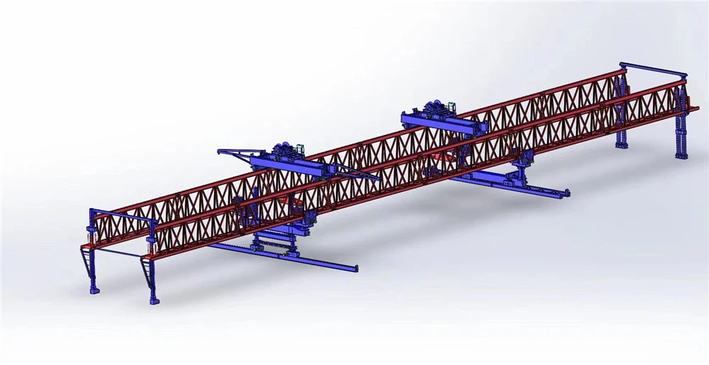
This is the "skeleton" and "legs" of the machine, responsible for carrying all loads and moving between bridge piers.
Main Girder (Machine Arm): The primary load-bearing member of the entire machine, typically a box girder or triangular truss structure. It spans across the front and rear legs and carries the full weight of the girder. For segmental erection machines, the main girder may be designed in sections for easy road transport and on-site assembly.
Leg System: The key components that support the main girder and enable the machine to move. It usually includes front, middle, and rear legs, and some models are also equipped with a zero column or front auxiliary leg. The leg height is usually adjustable to accommodate longitudinal slopes and varying span requirements.
🔗 Hoisting & Fine-Tuning System
This is the "hands" of the machine, responsible for smoothly lifting the 100-ton girder, moving it longitudinally, and positioning it accurately.
Hoisting Trolley (Girder Lifting Trolley): Located on top of the main girder, this is the main lifting mechanism. A 100T erection machine typically has two trolleys (e.g., 50t each) that operate synchronously to lift the entire girder. It integrates winches and pulley blocks for lifting, as well as longitudinal and transverse travel wheel boxes, allowing the trolley to move along the main girder and make transverse fine adjustments on the cross beam for millimeter-level positioning.
Cross Guide Beam (Transverse Travel Track): Sometimes considered part of the trolley system, it is mounted above the main girder and provides a track for the hoisting trolley to move transversely, adjusting the lateral position of the girder.
⚙️ Power & Control System
This is the "nerves" and "muscles" of the machine, providing power for all movements and ensuring precision and safety.
Power System: Mainly includes the hydraulic system and electrical system. The hydraulic system drives leg extension and adjustment actions, while the electrical system provides power for the travel and hoisting motors.
Control System: Typically includes electrical control cabinets, an operation console, or a remote control. Modern erection machines often use Variable Frequency Drive (VFD) technology for smoother lifting and traveling. Some models also integrate PLC control and safety monitoring systems to display real-time data such as load and wind speed.
🛡️ Safety & Auxiliary System
This is the key configuration for ensuring construction safety, as well as auxiliary devices for special working conditions.
Safety Protection Devices: Standard features include overload protection, limit switches, emergency stop buttons, anemometer (high-wind alarm), and anti-collision radar.
Auxiliary Structures: Such as front and rear leg connecting frames to enhance overall stability, and girder finishing platforms for workers to perform tasks.

Sketch

Advantages
A 100T bridge girder erection machine occupies a strategic middle ground in bridge construction equipment. It is large enough to handle the heavy precast girders used in most highway and municipal viaducts, yet agile and cost-effective enough to avoid the logistical burdens of massive, high-capacity gantries.
🎯 Precise Load-to-Span Adaptability
The 100-ton capacity is specifically optimized for the most common bridge construction scenarios, covering over 60% of highway, railway, and municipal bridge projects.
Handles Heavy Girders Directly: It can lift 40m T-beams (typically 80-95 tons) or 25m box girders (up to 90 tons) in a single lift, eliminating the need for risky, coordinated dual-crane "tandem lifting" required by smaller machines.
Avoids Costly Over-Engineering: Unlike 200-ton+ machines, it avoids unnecessary capital and operational expenses for "redundant lifting capacity" that is rarely needed in standard mid-span projects.
💰 Favorable Economics & Logistics
The machine's moderate size translates directly into significant savings in both time and money across the project lifecycle.
Lower Capital & Operating Costs: Acquisition or rental costs are roughly 50%-60% of a 200-ton machine. It also consumes 25%-40% less energy and requires smaller, cheaper transport vehicles (100-120 ton capacity).
Faster Deployment & Relocation: With a self-weight of only 150-250 tons (vs. 500+ tons for large models), it can be assembled and disassembled 30%-50% faster. It often self-launches ("walks") between spans without needing massive auxiliary cranes, boosting relocation efficiency by 20%-30% on multi-bridge projects.
🛡️ Enhanced Operational Safety & Control
By simplifying the lifting process, the 100T machine reduces the inherent risks of bridge erection.
Eliminates Tandem Lifting Risks: The single-machine lift removes the dangerous synchronization and communication challenges of using two smaller cranes to lift one girder.
Stable & Precise Placement: Modern units use VFD (Variable Frequency Drive) and PLC control for smooth starts/stops. The dual-trolley, four-point lifting system with electronic anti-sway ensures the girder remains stable, even in windy river-crossing conditions, allowing for millimeter-level positioning.
🏗️ Superior Site Adaptability
Its relatively compact footprint allows it to operate in environments where larger equipment simply cannot fit.
Narrow Site Friendly: It is well-suited for urban viaducts, mountain valleys, and rivers with restricted access, reducing the need for massive temporary platforms or water-based support structures.
Curve & Slope Capable: Models are typically designed to handle longitudinal slopes up to 3-5% and curve radii (e.g., R>200m to R>300m), accommodating the complex alignments common in modern infrastructure.
⚙️ High Versatility & Integration
The 100T machine is not limited to just one task, making it a versatile asset on site.
Multi-Functionality: It can serve as both a girder erection machine and a transfer device for unloading and storing beams, reducing the need for separate equipment.
Assembly-Line Construction: When paired with prefabricated piers and caps, it enables a rapid "assembly line" approach, reducing the time to install a single bridge span from 6-8 days down to as little as 4 days.
In summary, the 100T machine offers the "sweet spot" for mid-sized projects: it delivers the heavy-lifting muscle needed for real-world girders while maintaining the agility and cost-efficiency that larger equipment sacrifices.


Application
A 100T bridge girder erection machine is primarily deployed across four main application scenarios, spanning highway, railway, and municipal bridge construction.
🛣️ Highway & Expressway Bridges
This is the most common application for the 100T machine. It is the economic workhorse for medium-span highway viaducts and standard bridges.
Typical Projects: Provincial and lower-grade highway bridges, expressway overpasses, and standard medium-span river crossings.
Girder Types: Handles 40m T-beams (usually 80–95 tons) and 25–30m box girders in a single lift, avoiding risky dual-crane "tandem lifting".
Real-World Cases: Used in the Changning Expressway project (China) to erect 48m T-beams and in the Xixia Huangshi Grand Bridge for 40m T-beams and 25m box girders.
🏙️ Municipal Viaducts & Urban Rapid Transit
The machine's relatively compact footprint makes it suitable for urban environments where space is restricted and noise/dust control is critical.
Typical Projects: Urban elevated roads, rapid transit viaducts, and interchange ramps.
Construction Methods: Often used for segmental beam assembly ("building with blocks") or cross-pier gantry assembly. The Guangfo West Ring project used a DP100/40 machine to erect 112 spans of precast segments, which reduced on-site dust and noise-ideal for densely populated areas.
Site Advantages: Reduces the need for massive temporary platforms and is well-suited for narrow urban worksites.
🚄 Railway & Rail Transit
A variant of the 100T machine is specifically engineered for railway infrastructure, where girders are often heavier and precision requirements are stricter.
Typical Projects: High-speed railway bridge sections, subway tunnel equipment installation, and track assembly bases.
Design Features: Railway-specific machines often feature reinforced concrete supports for stability on uneven terrain and open-truss designs for better visibility during complex lifts.
Capacity Fit: The 100-ton rating is ideal for 10–50m span railway girders, filling the gap between small portable gantries and massive 200T+ machines.
⛰️ Complex Terrain & Restricted Sites
The 100T machine's lighter self-weight (typically 150–250 tons) and faster deployment make it the go-to choice when access is difficult or the project involves scattered bridge groups.
Mountainous Areas: Used where large auxiliary cranes cannot access. In the Xixia project, the team had to adopt a "middle-to-ends" erection strategy because the machine could not traverse end-to-end due to mountainous backfill and cast-in-place sections.
Multi-Bridge Projects: Its ability to self-launch ("walk") between spans without massive auxiliary cranes boosts relocation efficiency by 20–30%, making it ideal for projects with many discrete bridge structures.
Narrow Sites: The machine's modular design and lower ground pressure are advantageous in valleys, rivers, or urban sites with limited staging areas.

Production Procedure
Production Procedure of Heavy-Duty Bridge Erecting Machine
1. Design & Engineering
Requirements Analysis - Define bridge type, span length, rated capacity (e.g., 100T), and site conditions
Structural Design - Develop truss configuration, main girder dimensions, and load-bearing calculations
Finite Element Analysis (FEA) - Perform stress analysis and structural verification for safety compliance
Detailed Drawings - Produce fabrication drawings with precise dimensions and welding specifications
2. Material Preparation
Steel Selection - Procure high-strength structural steel (e.g., Q345B, S355) for main load-bearing components
Incoming Inspection - Verify material certificates and conduct mechanical property tests
Cutting - Use cutting machines or flame cutting to shape steel plates and sections according to drawings
Edge Preparation - Perform edge trimming, drilling, and beveling for weld joints
3. Fabrication & Welding
Surface Treatment - Remove rust, oil, and contaminants via sandblasting or grinding before welding
Welding Operations - Apply arc welding or gas welding for structural joints; ensure uniform, sound welds
Main Girder Fabrication - Weld truss modules including chords, diagonals, and cross beams
Quality Control - Inspect weld quality through visual examination and non-destructive testing (NDT)
4. Machining & Component Manufacturing
Precision Machining - Machine pin holes, bolt holes, and connection interfaces for accurate fit
Leg Assembly Fabrication - Manufacture front, middle, and rear leg structures with mounting flanges
Trolley & Winch Assembly - Build lifting trolleys, hoisting winches, and pulley blocks
Bogie Manufacturing - Produce travel bogies with wheels, axles, and drive mechanisms
5. Surface Treatment & Painting
Shot Blasting - Clean steel surfaces to Sa2.5 standard for coating adhesion
Primer Application - Apply anti-corrosion primer to all structural components
Topcoat Painting - Apply finish coats with specified color and thickness
Corrosion Protection - Optional hot-dip galvanizing or specialized coatings for harsh environments
6. Factory Pre-Assembly & Testing
Trial Assembly - Partially assemble main components to verify fit and dimensional accuracy
Mechanical Testing - Test winch operation, trolley travel, and bogie rotation
Electrical System Check - Verify PLC, VFDs, sensors, and control cabinet wiring
Load Test (Factory) - Conduct rated load and overload tests to validate lifting capacity
7. Disassembly & Shipping
Modular Disassembly - Break down into transportable modules with match-marking
Packaging - Protect components with wrapping, crating, and rust-preventive treatment
Shipping - Coordinate logistics for delivery to project site
Documentation - Prepare shipping list, assembly drawings, and operation manuals
8. On-Site Assembly
Site Preparation - Level and compact assembly area; ensure adequate space and access
Component Inspection - Verify all parts received and inspect for shipping damage
Foundation & Support - Install temporary supports or assemble on pre-built track
Leg Assembly - Position front, middle, and rear legs with temporary bracing
Main Girder Erection - Lift and connect main truss girders using cranes; verify alignment and parallelism
Cross Beam Installation - Install cross beams and bracing to integrate main girders
Trolley & Winch Installation - Mount lifting trolleys on main girder rails
Electrical & Hydraulic Connection - Connect control systems, sensors, and hydraulic lines
9. Commissioning & Load Testing
No-Load Trial Run - Test all motions: lifting, trolley travel, longitudinal/lateral movement
Safety Device Verification - Check overload limiter, limit switches, emergency stop, and anemometer
Rated Load Test - Lift 100T test load to verify structural integrity and performance
Overload Test - Conduct 110-125% overload test as per safety standards
Acceptance Inspection - Complete formal acceptance with client and regulatory authorities
10. Operation & Maintenance
Operator Training - Train operators on controls, safety procedures, and emergency protocols
Documentation Handover - Provide operation manuals, maintenance schedules, and spare parts lists
Scheduled Maintenance - Regular inspection of wire ropes, brakes, hydraulic fluids, and electrical systems
Ongoing Support - Provide technical support and spare parts availability throughout project duration


Workshop View
The company has installed an intelligent equipment management platform, and has installed 310 sets (sets) of handling and welding robots. After the completion of the plan, there will be more than 500 sets (sets), and the equipment networking rate will reach 95%. 32 welding lines have been put into use, 50 are planned to be installed, and the automation rate of the entire product line has reached 85%.


Hot Tags: 100t bridge girder erection machine, China 100t bridge girder erection machine manufacturers, suppliers, factory
You Might Also Like


Send Inquiry