







120 Ton Self-balancing Bridge Girder Erection Machine manufacturers

120 Ton Self-balancing Bridge Girder Erection Machine suppliers

120 Ton Self-balancing Bridge Girder Erection Machine factory

120 Ton Self-balancing Bridge Girder Erection Machine best

120 Ton Self-balancing Bridge Girder Erection Machine high quality
120 Ton Self-balancing Bridge Girder Erection Machine
A 120-ton self-balancing bridge girder erection machine is a specialized piece of heavy construction equipment used to lift and position precast concrete or steel bridge segments weighing up to 120 tons. Its defining feature is the ability to remain stable during the erection process without relying on large external counterweights or ground-based scaffolding.

| Parameter | Typical Range / Specification |
|---|---|
| Maximum Lifting Capacity | 120 tons |
| Bridge Span (Pier Distance) | ≤ 30 m to 40 m (some models support up to 50 m) |
| Adaptive Longitudinal Slope | ±3% to 5% |
| Adaptive Skew Angle | Up to 45° |
| Total Power | Approximately 65 kW to 96 kW |
Core Principle & How It Works
The "self-balancing" aspect is the machine's most critical engineering feature. Traditional erection machines often require heavy counterweights or a completed bridge section behind them to prevent tipping. A self-balancing machine, however, maintains stability through its own structural design and hydraulic systems.
Its primary application is in Balanced Cantilever Construction. Here's the typical process:
Positioning: The machine is assembled on top of a bridge pier (column).
Symmetric Lifting: It lifts a 120-ton segment on one side of the pier, then lifts an equal-weight segment on the other side. This creates a balanced cantilever extending outward from the pier in both directions.
Stressing & Moving: Once segments are secured with high-strength steel tendons, the machine uses a hydraulic "walking" or "launching" system to move forward onto the newly built deck, ready for the next segment.
This method eliminates the need for ground-level falsework (temporary scaffolding), making it ideal for construction over deep valleys, wide rivers, or busy roads where ground support is impossible or too disruptive.


Pictures & Components
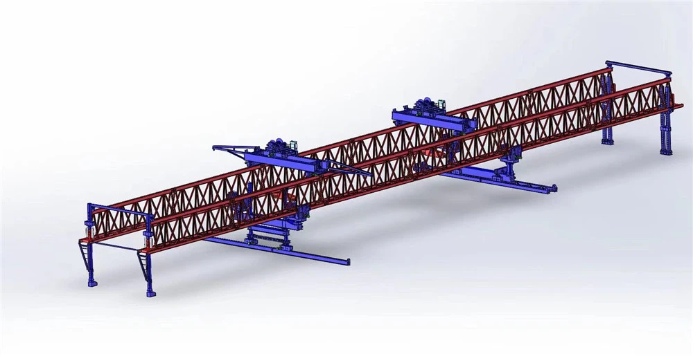
A 120-ton self-balancing bridge girder erection machine is mainly composed of the following components:
🏗️ Main Structural Components
1. Main Girder
The core load-bearing framework of the entire machine.
Usually a box-type or truss structure.
Can be assembled in sections (e.g., 12 m per section) for easy transport.
2. Front Auxiliary Leg
The key feature of a self-balancing erection machine.
Provides front support during launching (moving forward).
Enables self-balanced launching without the assistance of a girder transport vehicle.
3. Front Leg / Middle Leg / Rear Leg
Together they form the machine's support system.
Each leg is usually equipped with hydraulic telescopic or leveling cylinders.
Can be adjusted independently or synchronously to adapt to bridge deck slopes and curves.
4. Hoisting Trolley
Travels longitudinally along the main girder.
Responsible for lifting and longitudinally moving the girder segments.
Usually equipped with two trolleys or dual lifting points to achieve synchronized balanced lifting.
5. Transverse Moving Mechanism
Used for lateral movement of the lifted girder.
Used for lateral positioning of the entire machine.
Some models have a transverse trolley integrated into the hoisting trolley.
6. Hydraulic System
Provides power for leg extension/retraction.
Provides power for trolley traveling.
Provides power for the entire machine's walking-type launching.
Enables fine attitude adjustment and control.
7. Electrical & Control System
Includes PLC, sensors (load, inclination, displacement, etc.), and an operator cabin.
Through a closed-loop algorithm, it senses the center of gravity in real time.
Adjusts the legs and trolley positions to achieve dynamic self-balancing.
Horizontal error is controllable within ±2 mm.
8. Safety Protection Devices
Include overload protection.
Include travel limit switches.
Include emergency stop.
Include anemometer.
Include audible/visual alarms.
Ensure operational safety.

Sketch

Advantages
✅ Key Advantages
1. No Ground Support Needed
Operates entirely from the bridge structure itself.
Avoids costly and environmentally disruptive falsework on the ground.
Ideal for construction over deep valleys, wide rivers, or busy roads.
2. Faster Construction
Enables span-by-span erection without waiting for ground-based equipment.
Significantly reduces project timelines.
Minimizes interruptions caused by ground-level obstacles.
3. Adaptable to Difficult Terrain
Works effectively in mountainous areas.
Suitable for construction over water.
Operates well in urban environments.
Functions efficiently at tunnel portals.
Reaches locations where traditional cranes cannot operate.
4. Enhanced Safety
Reduces the need for workers at dangerous heights.
Keeps workers away from lifting zones below.
Built-in safety systems include overload protection and synchronized lifting.
Minimizes risk to personnel and equipment.
5. Self-Balancing Stability
Maintains stability through its own structural design and hydraulic systems.
Eliminates the need for large external counterweights.
Does not rely on ground-based scaffolding.
Ensures safe operation during cantilever construction.
6. Minimal Disruption to Existing Infrastructure
Suitable for building over roads and railways.
Reduces interference with traffic below.
Minimizes disturbance to rivers and waterways.
Ideal for urban interchanges and elevated road networks.
7. High Precision and Control
PLC-based control system with real-time sensors.
Closed-loop algorithm maintains dynamic balance.
Horizontal error controllable within ±2 mm.
Ensures accurate segment positioning.
8. Cost Efficiency
Reduces the need for temporary ground structures.
Lowers labor and material costs.
Shortens overall construction time.
Improves project return on investment.

Application
📍 Common Applications
1. Highway Bridges
Used for erecting precast concrete girder segments on highway viaducts.
Suitable for long-span elevated road sections.
Enables construction without disrupting traffic below.
2. Railway Bridges
Widely used in high-speed rail projects.
Suitable for long-span railway viaducts.
Ensures precise segment positioning for rail alignment.
3. Urban Interchanges
Ideal for complex, curved, and elevated road networks.
Works from a single point above piers.
Minimizes disruption in densely populated areas.
4. Projects Over Existing Infrastructure
Building over roads and highways with minimal traffic disruption.
Constructing over railways without interrupting rail operations.
Erecting spans over rivers and waterways.
5. Mountainous and Difficult Terrain
Construction in deep valleys where ground support is impossible.
Suitable for steep slope areas.
Works at tunnel portals where space is limited.
6. Balanced Cantilever Construction
The primary application method for this type of machine.
Lifts equal-weight segments symmetrically on both sides of a pier.
Extends the cantilever outward in both directions.
Ideal for long-span bridges without ground falsework.
7. Curved and Skew Bridges
Adaptable to bridge curves and skew angles.
Handles skew bridge angles up to 45°.
Suitable for complex alignment requirements.
8. Water Crossing Bridges
Construction over wide rivers and lakes.
Avoids the need for barges or ground-based cranes.
Reduces environmental impact on water bodies.
9. Precast Segment Assembly
Lifts and positions precast concrete segments weighing up to 120 tons.
Suitable for span-by-span erection methods.
Enables rapid assembly of bridge superstructures.
10. Steel Girder Erection
Also used for lifting and positioning steel bridge segments.
Suitable for composite bridge construction.
Adaptable to various bridge design types.

Production Procedure
🏭 Production Procedure
Phase 1: Engineering & Planning
Finalize detailed engineering drawings, Bill of Materials (BOM), and hydraulic/electrical schematics.
Establish manufacturing sequence, welding procedures, and quality inspection plans.
Initiate procurement of all required materials (steel plates, sections, bearings, hydraulic components, electrical components).
Phase 2: Material Procurement & Inspection
Receive and log raw materials such as structural steel and plates.
Inspect materials for grade, dimensions, and surface defects against mill certificates and purchase orders.
Quarantine any non-conforming materials.
Phase 3: Steel Fabrication
Marking & Cutting: Mark steel plates and sections according to nesting drawings to optimize material usage. Perform cutting using CNC plasma/oxy-fuel cutters or saws for high precision.
Forming & Bending: Form plates requiring curvature (e.g., for gussets, custom brackets) using press brakes or rolling machines.
Welding: Weld structural components according to approved welding procedures and quality standards.
Phase 4: Machining of Critical Components
Machine critical components (e.g., pins, shafts, bearing seats) to precise tolerances.
Ensure interchangeability and proper fit for assembly.
Phase 5: Sub-assembly & General Assembly
Assemble sub-units such as legs, trolleys, and support frames.
Perform general assembly of the main truss/girder, front support (nose), rear support, and counterweight frame (if applicable).
Install the launching gantry/trolley on the main truss.
Phase 6: Installation of Mechanical & Hydraulic Systems
Install hydraulic cylinders, pumps, valves, and hoses.
Connect mechanical linkages and ensure proper alignment.
Phase 7: Electrical & Control System Integration
Install motors, sensors, PLCs, and the operator's cabin.
Route and connect electrical cables and control lines.
Integrate the control system for precise operation.
Phase 8: Factory Acceptance Testing (FAT)
Conduct no-load tests to verify all functions (lifting, launching, traversing, leg adjustment).
Conduct load tests to confirm rated capacity and structural integrity.
Verify safety devices (overload protection, limit switches, emergency stop).
Phase 9: Surface Treatment & Painting
Prepare surfaces for painting (cleaning, descaling).
Apply primer and finish coats for corrosion protection.
Phase 10: Dismantling, Packaging & Shipping
Dismantle the machine into transportable sections.
Package components securely for shipment.
Prepare shipping documentation and load for dispatch.


Workshop View
The company has installed an intelligent equipment management platform, and has installed 310 sets (sets) of handling and welding robots. After the completion of the plan, there will be more than 500 sets (sets), and the equipment networking rate will reach 95%. 32 welding lines have been put into use, 50 are planned to be installed, and the automation rate of the entire product line has reached 85%.


Hot Tags: 120 ton self-balancing bridge girder erection machine, China 120 ton self-balancing bridge girder erection machine manufacturers, suppliers, factory
You Might Also Like


Send Inquiry