










180 Tons Bridge Lancher For Precast Concrete Beam
A 180 Tons Bridge Lancher for Precast Concrete Beam refers to a major piece of heavy equipment used to erect prefabricated bridge segments (girders, box beams, etc.) into their final position on piers and abutments.
A 180-ton bridge launcher is a specialized piece of heavy machinery designed to lift and precisely place precast concrete beams (like T-beams or box girders) onto bridge piers. Its primary advantage is the ability to erect spans without needing temporary ground supports, making it essential for crossing rivers, valleys, or existing infrastructure

Core Function
The primary purpose of a 180ton bridge launcher is to lift, transport, and precisely place heavy prefabricated concrete or steel bridge components, typically weighing up to 180 tons (metric tons, ~165 US tons), during the construction of viaducts, overpasses, and highway bridges.
Key Design Parameters & Performance Specifications
| Parameter | Specification |
|---|---|
| Lifting Capacity (per girder) | 180 Metric Tons |
| Maximum Span (Pier to Pier) | 50 meters (Typical), customizable up to 60m |
| Minimum Curve Radius | 2,000 meters (can be designed for tighter radii) |
| Maximum Supported Grade | ±4% |
| Lifting Hoists | 2 x Main Hoists (typically 120-ton capacity each) |
| Hoist Lifting Speed | 0-5 m/min (variable speed control) |
| Trolley Traversing Speed | 0-10 m/min (variable speed control) |
| Main Beam Launching Speed | 0-5 m/min (variable speed control) |
| Machine Self-Propelling Speed | 0-5 m/min (variable speed control) |
| Control System | Centralized PLC with frequency control for all motions. Remote control operation. |
| Power Supply | 380V / 50Hz / 3 Phase (or as per project requirement) |

Pictures & Components
1. Main Structural Steel Structure (The "Bones & Muscles")
This is the primary load-bearing framework that directly handles the 150-ton segments.
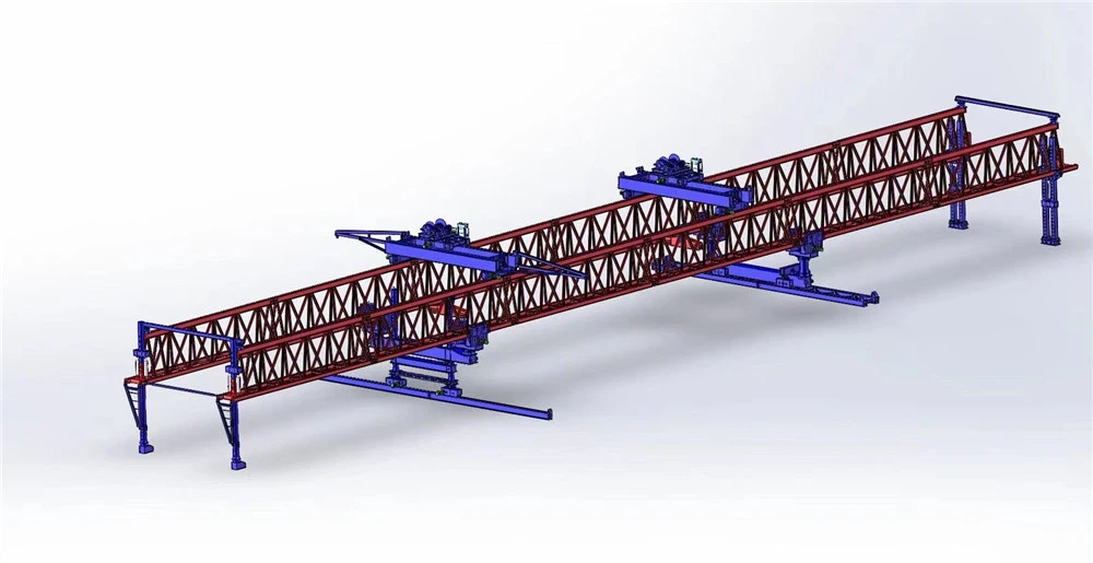
Main Gantry/Gantry Frame: The primary overhead steel truss or box girder structure that spans the width of the bridge deck and often part of the constructed span. It provides the traveling path for the lifting trolley and supports all other components.
Front Support (Nose or Cantilever Support): Extends over the pier where the next segment will be placed. It often includes adjustable legs to align with the new pier.
Rear Support (Main Support): Anchors the gantry on the already constructed deck or previous pier. It distributes the machine's weight and reaction forces.
Lifting Beam/Spreader Beam: A robust, often adjustable beam that connects to the segment lifting points via rods or cables. It ensures the segment is lifted evenly and without undue stress.
Trolley (Traversing Cart): The moving unit that runs along rails on the main gantry. It houses the winches or hydraulic cylinders for vertical lifting and horizontal movement of the segment.
Temporary Stay / Backstay Towers (if applicable): For balanced cantilever launching or when launching over long spans, these temporary towers provide additional stability and moment resistance.
2. Hydraulic & Mechanical Drive Systems (The "Muscles & Sinews")
These systems provide the precise force and movement for all operations.
Lifting Hydraulic Jacks/Cylinders: High-capacity, synchronized hydraulic cylinders (usually at least two, often four) mounted on the trolley. They provide the vertical lifting force (150+ tons).
Segment Adjustment Jacks: Smaller, multi-directional (often 3 or 4-axis) hydraulic jacks mounted on the lifting beam or trolley. They allow for fine-tuning the segment's position in all directions (vertical, lateral, longitudinal, and rotation) before permanent connection.
Gantry Propulsion System:
Propulsion Hydraulic Jacks: Push-pull cylinders that "walk" the entire gantry structure forward to the next work position after a segment is placed.
Clamping Devices: Hydraulic clamps that grip the bridge deck or pier to provide a reaction point for the propulsion jacks.
Winch System: In some designs, electric or hydraulic winches with high-strength wire ropes are used for lifting instead of direct hydraulic cylinders.
Hydraulic Power Unit (HPU): The heart of the hydraulic system, consisting of diesel or electric motor-driven pumps, reservoirs, valves, filters, and cooling systems. It generates and regulates the high-pressure hydraulic fluid flow.
3. Control & Monitoring Systems (The "Brain & Nerves")
Ensures precision, synchronization, and safety.
Main Programmable Logic Controller (PLC): The central computer that automates and sequences all movements (lifting, trolley travel, gantry launch).
Synchronization Control System: Critical for lifting. It ensures all lifting jacks move in perfect unison to keep the segment level, preventing dangerous tilting or overstress. This is often done via laser sensors or encoders with feedback loops to the PLC.
Operator Control Cabin/Remote Control: A protected cabin on the gantry or a wireless remote control station from which the operator oversees all operations.
Monitoring & Safety Sensors:
Load Cells: Installed in the lifting system to measure and display the actual load on each jack (preventing overload).
Inclinometers: Monitor the level of the segment and the gantry itself.
Limit Switches & Position Encoders: Provide precise positioning data for all moving parts.
Anemometer: Measures wind speed; operations are halted if limits are exceeded for safety.
4. Auxiliary & Support Systems (The "Support System")
Electrical System: Generators, distribution panels, cable reels, and lighting for night work.
Safety Systems: Guardrails, access ladders, platforms, emergency stop buttons, and fall protection systems for personnel.
Epoxy Application System (for segmental bridges): A metered system to apply the epoxy resin layer between match-cast segments before joining.

Sketch

Advantages
1. High Lifting Capacity 💪
With a 180-ton capacity, the launcher can handle large precast girders (such as box girders or I-beams), reducing the need to split beams into smaller segments. This improves structural integrity and speeds up installation.
2. Faster Construction Speed ⏱️
Bridge launchers enable segment-by-segment erection directly from above, minimizing reliance on ground-based cranes. This is especially useful for long viaducts and repetitive spans, significantly accelerating project timelines.
3. Reduced Ground Dependency 🌍
Unlike traditional cranes, the launcher operates on the bridge structure itself, which is ideal for:
Rivers
Valleys
Urban areas with limited space
Environmentally sensitive zones
4. Improved Safety 🦺
Less need for heavy lifting from the ground
Reduced worker exposure to hazardous conditions below
More controlled beam placement
5. Precision Placement 🎯
Bridge launchers provide accurate alignment and positioning of precast beams, which is critical for maintaining geometry and load distribution in the bridge.
6. Cost Efficiency 💰
Although the initial investment is high, it reduces:
Labor costs
Crane rental costs
Construction time
This often leads to overall project savings, especially for large-scale or repetitive bridge projects.
7. Adaptability 🔧
Modern launchers can be configured for:
Different span lengths
Various girder types (T-beams, box girders, U-girders)
Incremental launching or span-by-span methods
8. Minimal Traffic Disruption 🚧
In highway or railway projects, erection can occur above existing traffic, reducing closures and public inconvenience.
9. Environmental Benefits 🌱
Less need for temporary supports or scaffolding
Reduced impact on terrain and waterways
Lower noise and dust compared to ground-heavy operations

Application
1. Highway Viaduct Construction 🛣️
Widely used for elevated highways and expressways
Ideal for long stretches with repetitive spans
Common in urban flyovers and ring roads
2. Railway & High-Speed Rail Projects 🚄
Used for placing precast girders in railway bridges and metro lines
Essential in high-speed rail projects, where alignment precision is critical
3. Urban Elevated Structures 🌆
Metro viaducts and elevated transit systems
Works efficiently in dense cities with limited space and heavy traffic
Reduces disruption at ground level
4. River & Valley Crossings 🌉
Suitable for bridges over:
Rivers
Deep valleys
Flood-prone areas
Eliminates the need for temporary supports in difficult terrain
5. Segmental Box Girder Bridges 🧱
Used for precast segmental construction (span-by-span or balanced cantilever)
Handles heavy segments up to 180 tons with precision
6. Long Multi-Span Bridges 📏
Best suited for projects with many identical spans
Improves efficiency through repetitive operations
7. Overpasses & Interchanges 🔄
Common in complex road interchanges
Can operate above existing roads without major closures
8. Remote or Challenging Locations 🏞️
Mountainous areas or sites with poor ground access
Reduces need for large crane mobilization
9. Precast Beam Installation (I-Girders / T-Beams) 🏗️
Specifically designed for:
I-girders
T-beams
U-girders
Ensures safe and accurate placement of heavy precast elements
In short, a 180-ton launcher is most valuable in large-scale, repetitive, and hard-to-access bridge projects where speed, safety, and precision are critical.

Production Procedure
The production procedure for using a 180-ton bridge launcher (launching gantry) to erect precast concrete beams follows a well-defined sequence from fabrication to final placement. Here's a clear, step-by-step overview:
1. Precast Beam Fabrication 🧱
Beams (I-girders, T-beams, or box girders) are cast in a precast yard
Use of prestressing (pre/post-tensioning) for strength
Curing, quality checks, and dimensional inspection
Beams are marked and stored for transport
2. Transport to Site 🚚
Beams are delivered using trailers or transport bogies
Delivered either:
Directly under the launcher, or
To a staging area near the bridge
3. Launcher Assembly & Setup 🏗️
The 180-ton launching gantry is assembled on-site
Positioned on completed piers or abutments
Includes:
Main girder frame
Lifting winches/trolleys
Support legs (front & rear)
सिस्टम checks and load testing are conducted before operation
4. Launcher Positioning (Span Preparation) 📏
The launcher moves forward to the next span
Front leg rests on the next pier, rear leg on the previous span
System is aligned and stabilized
5. Beam Lifting Process ⬆️
Precast beam is placed under the launcher
Hoisting system (winches or strand jacks) lifts the beam
Beam is suspended securely with lifting frames
6. Beam Traveling (Longitudinal Movement) ➡️
The lifted beam is moved along the launcher girder
Trolleys carry the beam to the correct span position
7. Beam Placement & Alignment 🎯
Beam is lowered onto bearings on piers/abutments
Fine adjustments ensure:
Correct alignment
Proper seating on elastomeric or pot bearings
8. Temporary Fixing & Stabilization 🔧
Beam is temporarily secured using:
Bracing
Shear keys or clamps
Prevents movement before full deck integration
9. Repetition for Remaining Beams 🔁
Process is repeated for all beams in the span
Typically multiple girders per span
10. Launcher Forward Launching 🚀
Once a span is complete:
The launcher moves forward to the next span
Uses its own mechanism (self-launching system)
11. Deck Construction 🛣️
After all beams are placed:
Formwork and reinforcement installed
Deck slab is cast
Post-tensioning (if required)
12. Final Finishing Works ✅
Parapets, barriers, and surfacing
Drainage and utilities installation
Final inspection and load testing


Workshop View
The company has installed an intelligent equipment management platform, and has installed 310 sets (sets) of handling and welding robots. After the completion of the plan, there will be more than 500 sets (sets), and the equipment networking rate will reach 95%. 32 welding lines have been put into use, 50 are planned to be installed, and the automation rate of the entire product line has reached 85%.


Hot Tags: 180 tons bridge lancher for precast concrete beam, China 180 tons bridge lancher for precast concrete beam manufacturers, suppliers, factory
You Might Also Like


Send Inquiry