










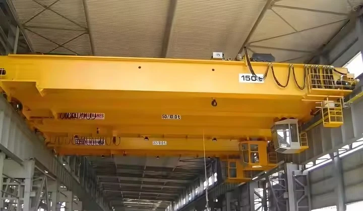
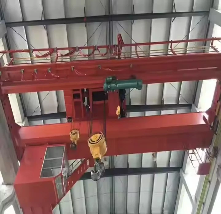


Two Speed Overhead Crane Remote Control
Products Description
Dual-Speed Modes:
High Speed – For faster movement when handling lighter loads or when precision is less critical.
Low Speed – For precise positioning, especially when handling heavy or delicate loads.
Functions Controlled:
Hoisting (Up/Down) – Adjustable lifting/lowering speeds.
Trolley Travel (Left/Right) – Controls the bridge trolley movement.
Bridge Travel (Forward/Backward) – Controls the crane's longitudinal movement.
Safety & Ergonomics:
Emergency stop button.
Waterproof, dustproof, and shock-resistant designs (common in industrial-grade remotes).
Ergonomic design for comfortable operation.
Wireless or Wired Options:
Wireless (Radio Remote Control) – Typically operates on 2.4 GHz frequency with a range of up to 100 meters (interference-resistant).
Wired (Pendant Control) – Physically connected to the crane, often used in hazardous environments where wireless signals are restricted.
Benefits of Two-Speed Control:
Improved Precision: Slower speeds allow for careful load placement.
Efficiency: Faster speeds reduce idle time when moving unloaded or lightly loaded cranes.
Reduced Wear & Tear: Lower speeds minimize mechanical stress on motors and brakes.
Safety: Better control reduces the risk of load swings or collisions.

Pictures & Components
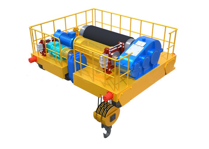
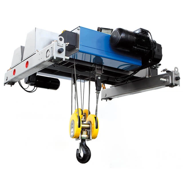
A two-speed overhead crane remote control system consists of several key components that work together to enable dual-speed operation for hoisting and traveling functions. Below is a breakdown of the essential components:
1. Transmitter (Remote Control Unit)
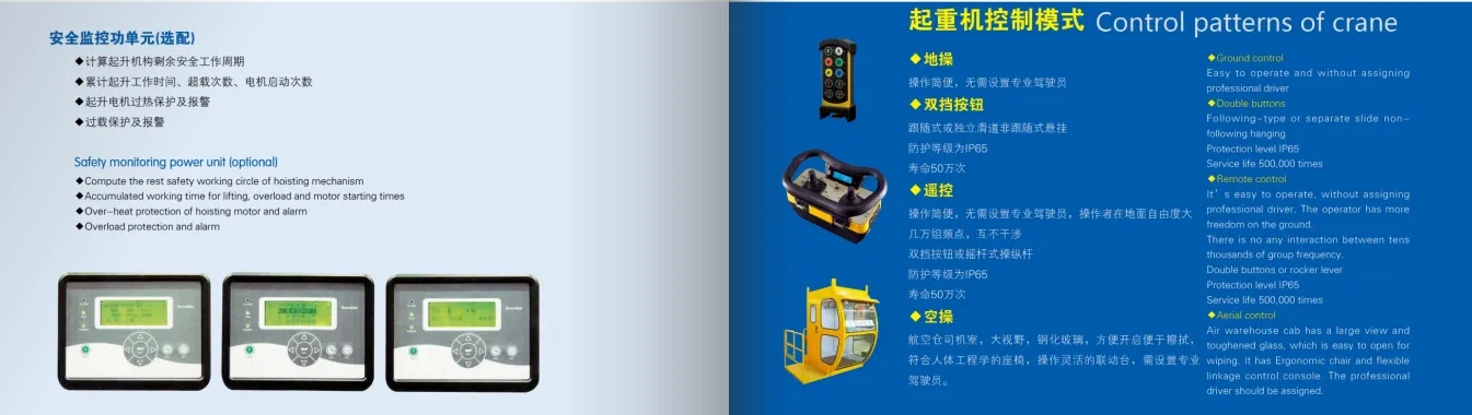
Wireless Remote (Radio Control)
Buttons/Switches: Dedicated controls for high/low speed selection (hoist, trolley, bridge).
Emergency Stop (E-Stop): Instantly cuts power to the crane in emergencies.
Antenna: Transmits signals to the receiver (typically 2.4 GHz for interference resistance).
Battery: Rechargeable lithium-ion or AA batteries (with low-battery indicators).
Enclosure: Rugged, waterproof (IP65/IP67) for industrial environments.
Wired Pendant Control
Hanging Push Buttons: Includes dual-speed selector switches.
Cable & Strain Relief: Reinforced for durability.
 |
 |
2. Receiver Unit
Mounted on the Crane: Receives signals from the remote.
Relays/Contactors: Switches between high and low speeds.
Safety Interlocks: Prevents accidental activation.
Frequency Hopping (for wireless): Avoids interference from other devices.
 |
 |
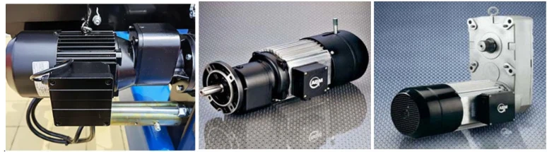
3. Motor Control Components
Two-Speed Hoist Motor:
Winding Configuration: Often pole-changing (2-speed) induction motor (e.g., Dahlander winding) or separate winding motors.
Contactors/K1, K2, K3: Used to switch between speeds.
Variable Frequency Drive (VFD) (Optional):
Allows smooth speed transitions (instead of fixed dual speeds).
Provides better control and reduces mechanical stress.
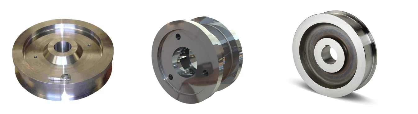
4. Speed Selection & Control Circuit
Speed Selector Switch (Remote & Control Panel):
Toggles between High (Fast) and Low (Slow) modes.
Control Relays & Timers:
Ensures smooth transition between speeds to prevent motor damage.
Limit Switches:
Prevents over-travel in high-speed mode.
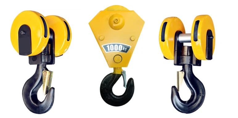
5. Power Supply & Safety Components
Circuit Breakers/Fuses: Protects against electrical faults.
Overload Relay: Prevents motor burnout due to excessive load.
Braking System:
Mechanical Brake (for hoist): Engages when power is cut.
Regenerative Braking (if using VFD): Slows the motor smoothly.

6. Additional Optional Components
Feedback System (Encoder/Sensor): Provides real-time speed monitoring.
PLC (Programmable Logic Controller): For advanced automation and safety logic.
HMI (Human-Machine Interface): Displays crane status (speed, load, errors).
.

How Two-Speed Control Works
Operator selects speed (High/Low) on the remote.
Signal sent to receiver → triggers corresponding contactors.
Motor windings reconfigure (for pole-changing motors) or VFD adjusts frequency.
Crane moves at selected speed with controlled acceleration/deceleration.

Common Wiring Configurations for Two-Speed Motors
| Motor Type | Wiring Method | Speed Change Mechanism |
|---|---|---|
| Dahlander Pole-Changing | 2Y/Δ (Star/Delta) or Y/YY | Changes pole pairs |
| Separate Winding | Two independent windings | Switches between windings |
SKETCH

Main technical

Advantages
Enhanced Precision & Safety
Low-speed mode enables millimeter-accurate load positioning, critical for:
Delicate component assembly
High-value cargo handling
Hazardous material movement
Eliminates dangerous load swing through controlled acceleration/deceleration
Optimized Productivity
High-speed mode (2-4x faster) reduces non-productive time when:
Moving empty hooks
Transporting lightweight loads
Positioning equipment between workstations
Typical cycle time improvements: 15-30%
Extended Equipment Life
Reduces mechanical stress by:
Minimizing gearbox shock loads (up to 40% less wear)
Decreasing brake lining degradation
Lowering motor overheating incidents
Energy Efficiency
Power consumption reduction strategies:
30-50% lower energy use in precision mode
Smart load-sensing systems (in advanced models)
Ergonomic Operation
Programmable speed ramping reduces operator fatigue
Wireless models provide 100-150m operational freedom
Application:
| Industry | High-Speed Use Cases | Low-Speed Use Cases | Benefit Realized |
|---|---|---|---|
| Steel Mills | Empty ladle transfer | Molten steel pouring | Prevents spillage (saves $5k+/incident) |
| Precast Concrete | Mold transport | Slab positioning (±2mm accuracy) | Reduces rework by 90% |
| Power Generation | Turbine housing movement | Stator winding installation | Prevents $250k+ component damage |
| Automotive | Body panel transfers | Engine block mating | Saves 12 sec/cycle in assembly |
| Shipping Ports | Container gantry traversal | Ship hold loading | Increases TEU throughput by 18% |
| Aerospace | Tooling positioning | Wing spar placement | Achieves 0.1° alignment tolerance |
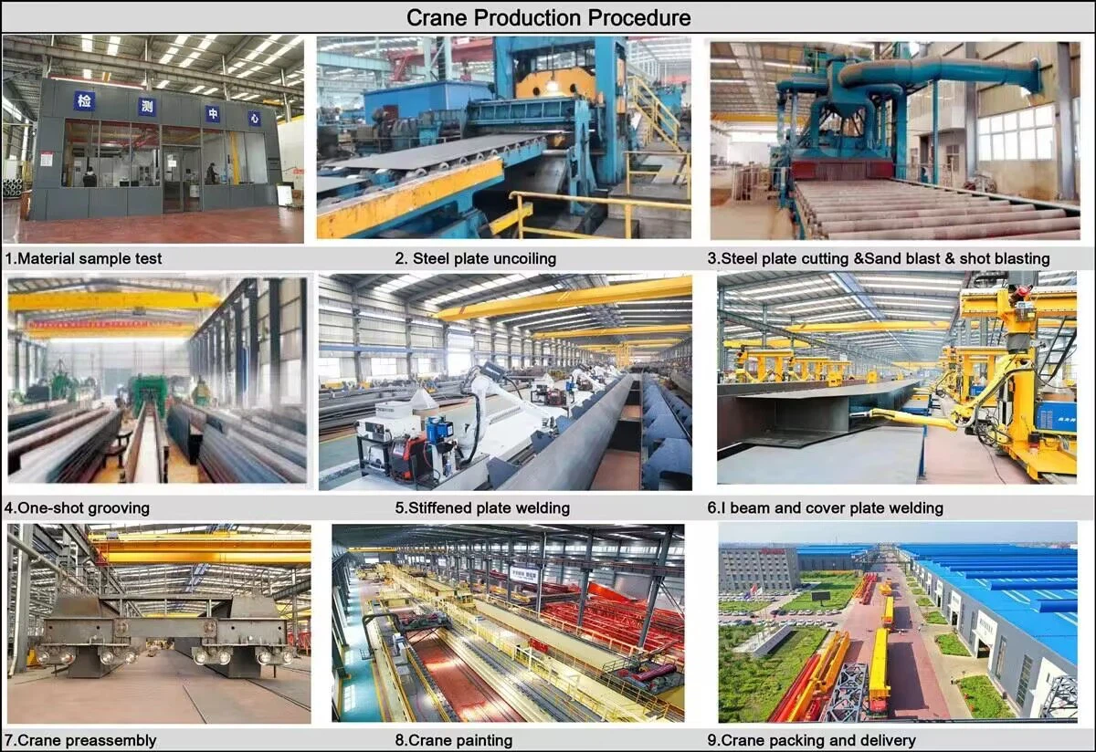
Crane production procedure
1.Design and Engineering
Requirements Gathering:
Load capacity (e.g., 10T, 50T, 100T, etc.), span, lifting height, and operational environment are defined.
Customization needs are assessed, such as control modes (pendant, wireless, cabin) and special features (e.g., anti-collision, overload protection).
Preliminary Design:
Structural engineers and crane designers create the crane's initial design, including the main beam, end carriage, lifting system, trolley system, travel mechanism, and other components.
Calculation and Simulation:
Load calculations are performed to ensure the crane can handle the specified capacity.
Finite element analysis (FEA) may be used to simulate stresses and deflections in the structure to ensure safety and stability.
Detailed Design:
After approval, detailed drawings for each part are made, including the main girder, end carriage, hoist system, motors, control systems, and safety features.
2. Material Procurement
Raw Material Selection:
High-quality materials like steel, alloyed steel, forged steel, and electrical components are sourced according to specifications.
Materials are inspected for quality certification and compliance with industry standards (e.g., ISO, CE).
Component Sourcing:
Standard components such as motors, hoists, control panels, limit switches, and safety devices are sourced from reliable suppliers.
3. Fabrication of Components
Main Girder:
Cutting and welding of steel plates to form the bridge girder.
The girder is assembled by welding or bolting sections, ensuring it meets the required strength and precision.
End Carriage Assembly:
The end carriage is fabricated and assembled to hold the crane on the runway rails.
Wheel assemblies are installed to ensure smooth travel along the rails.
Hoist and Trolley System:
The hoist unit (electric or manual) is assembled, including the drum, wire rope, hook, and motor.
The trolley system is built to transport the hoist across the bridge, including trolley wheels and drive mechanisms.
Crane Traveling Mechanism:
The crane wheels are mounted on the end carriages, ensuring smooth horizontal movement.
The drive system is installed to control travel speed.
4. Assembly of Crane
Main Beam Installation:
The assembled main girder is lifted and positioned onto the end carriages.
The girder is aligned to ensure structural integrity.
Trolley and Hoist Installation:
The trolley system is mounted onto the main girder, and the hoist is mounted to the trolley.
The load chain or wire rope is installed and tested for smooth operation.
Travel Mechanism Setup:
The crane wheels are fitted, and the drive mechanism is connected to the control system for horizontal movement.
5. Electrical and Control System Installation
Wiring and Control Panel:
The control panel is installed and wired to manage all crane movements (hoisting, trolley, crane travel).
Limit switches, emergency stop buttons, and safety alarms are integrated into the control system.
Motor and Gear Installation:
Motors for hoisting, traveling, and the trolley are installed and connected to their respective gear systems.
Testing of Control Systems:
Control systems are checked to ensure proper integration of pendant control, wireless remote, or cabin control options.
6. Testing and Quality Control
Load Testing:
The crane undergoes static load testing (to check stability) and dynamic load testing (to check operational performance under actual working conditions).
Overload protection and limit switches are tested to ensure they function correctly.
Safety System Testing:
The sound and light alarms, limit switches, emergency stop buttons, and safety devices are all tested for functionality.
Movement Testing:
All movements-hoisting, trolley movement, bridge travel, and sway control-are tested for smooth operation and precision.
Electrical Testing:
All electrical components are tested for proper wiring, grounding, and communication between systems.
Documentation and Certification:
The crane is inspected according to international safety standards and undergoes certification by relevant authorities (e.g., CE, ISO).
Test certificates for motors, cranes, and load testing are prepared.
7. Final Inspection and Painting
Visual Inspection:
A thorough inspection is carried out to ensure that the crane meets design specifications and safety requirements.
Painting:
The crane is painted with high-quality anti-corrosion coatings to protect it from environmental conditions.
Marking and Labeling:
Safety labels, warnings, and capacity markings are applied to the crane for proper identification.
8. Delivery and Installation
Shipping:
The crane is carefully disassembled into transportable parts (if needed) and shipped to the customer's location.
Installation:
The crane is installed on-site, and all connections (power, mechanical, control) are made.
Final Commissioning:
The crane is commissioned by running it through a series of operational tests to ensure it works properly.
Operator training is conducted, if necessary, for safe and efficient use.
9. Post-Installation Support
Customer Training:
Operator training on how to use the crane safely and effectively.
Maintenance Schedule:
Providing a maintenance plan for the crane's continued operation, including regular inspections, lubrication, and testing.
After-Sales Support:
Offering spare parts, troubleshooting, and repair services.
Workshop view:
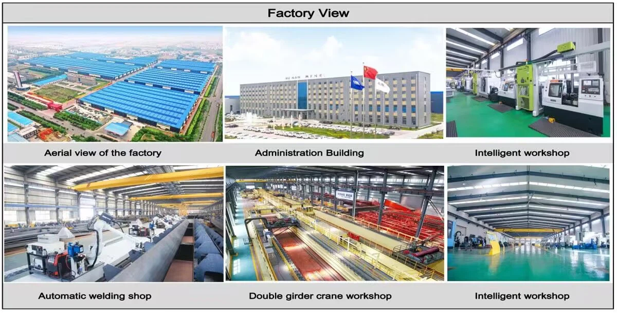
The company has installed an intelligent equipment management platform, and has installed 310 sets (sets) of handling and welding robots. After the completion of the plan, there will be more than 500 sets (sets), and the equipment networking rate will reach 95%. 32 welding lines have been put into use, 50 are planned to be installed, and the automation rate of the entire product line has reached 85%.


Hot Tags: two speed overhead crane remote control, China two speed overhead crane remote control manufacturers, suppliers, factory, Double Girder Overhead Crane, Double Girder Overhead Travelling Crane
You Might Also Like


Send Inquiry