










Explosion-proof Double Girder Overhead Crane
Products Description
Why Choose an Explosion-Proof Double Girder Crane?
✔ Handles extreme loads safely in explosive atmospheres
✔ Longer service life with heavy-duty construction
✔ Customizable explosion-proof features for different hazard zones
✔ Smoother, more precise control with VFDs and automation options
Comparison: Single vs. Double Girder Explosion-Proof Cranes
| Feature | Double Girder | Single Girder |
|---|---|---|
| Load Capacity | 5–550+ tons | 1–20 tons |
| Span Length | Longer spans (ideal for large facilities) | Shorter spans |
| Lifting Height | Higher hook height (no hoist below girder) | Lower due to under-hung design |
| Stability | More rigid, less sway | Moderate stability |
| Cost | Higher initial cost | More economical |
| Best For | Heavy-duty, high-risk industries | Light-to-medium hazardous loads |
Lifting Capacity 5 tons – 550 tons (customizable)
Span 10m – 35m (extendable with modular design)
Lifting Height 6m – 30m (adjustable)
Work Duty FEM 1Am – 3m (Medium to Heavy Duty)
Ambient Temperature -20°C to +60°C (special coatings for extreme conditions)
Power Supply 3-phase, 380V/415V/480V, 50/60Hz
Control Voltage 24V/36V (intrinsically safe for hazardous zones)
Speed Options - Lifting: 0.5–15 m/min (adjustable via VFD)
- Trolley Travel: 5–30 m/min
- Crane Travel: 10–60 m/min
Protection Grade IP65 (hoist), IP55 (crane structure)

Pictures & Components
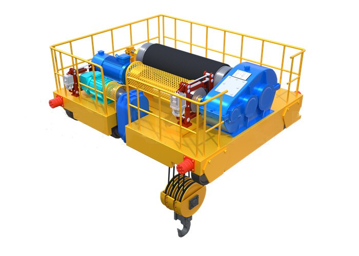
Structural Components
| Component | Explosion-Proof Features | Technical Specifications |
|---|---|---|
| Box-Type Girders (2) | - Sandblasted & coated with anti-static epoxy paint - Sealed welds prevent dust ingress |
- Material: Q235B/Q345B steel - FEM/ISO 12485 compliant - Deflection ≤ Span/1000 |
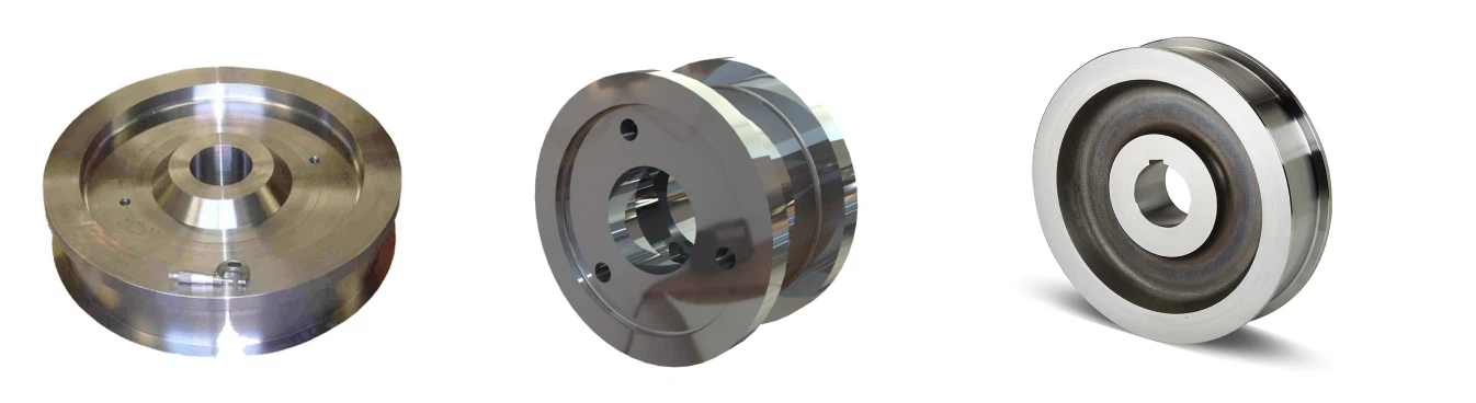
| Explosion-Proof End Trucks | - Double-wheel design with Ex-rated bearings - Spark-resistant brake discs |
- Wheel material: 55Mn forged steel - Wheel diameter: Φ400-Φ900mm |
| Runway System | - Insulated conductor bars (for Zone 1) - Galvanized runway beams |
- Parallelism tolerance: ±5mm over 10m - Crane rail: QU70/QU80/QU120 |
 |
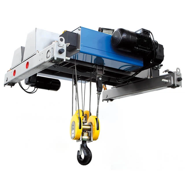 |
2. Lifting Mechanism
| Component | Ex Certification | Key Parameters |
|---|---|---|
| Ex Hoist Unit | - Motor: Ex d IIB T4 (flameproof) - Gearbox: Oil-immersed spark containment |
- Capacity: 5-550t - Speed: 0.5-15m/min (VFD adjustable) - Duty: FEM 2m/3m |
| Anti-Static Rope | - Conductive steel wire rope (resistance <10⁷Ω/m) - Non-sparking thimble sockets |
- Diameter: Φ12-Φ85mm - Minimum breaking force: 6×SWL |
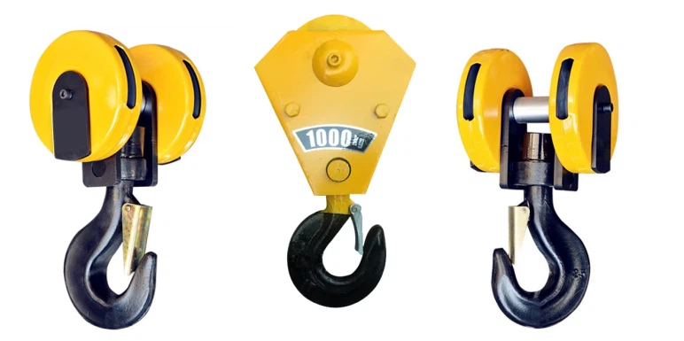
| Ex Hook Block | - Grounding brush for static discharge - Rotating bearing with Ex-certified grease |
- SWL: 5-550t - Safety factor: 6:1 - Hook rotation: 360° free |
 |
 |
3. Electrical & Control System
| Component | Protection Method | Technical Details |
|---|---|---|
| Ex Control Cabinet | - Pressurized (Ex px) or flameproof (Ex d) - Automatic gas detection system |
- PLC: Siemens S7-1200 Ex version - VFD: ABB ACS880-07 with Ex barrier |
| Ex Festoon System | - Corrosion-resistant copper conductors - Explosion-proof cable glands (Ex e) |
- Current: Up to 400A - IP rating: IP66 - Temperature range: -40°C to +60°C |
| Ex Limit Switches | - Intrinsically safe (Ex ia) magnetic proximity sensors - Dual-circuit redundancy |
- Repeat accuracy: ±2mm - Protection: IP68 |
4. Drive System
| Component | Safety Features | Performance Data |
|---|---|---|
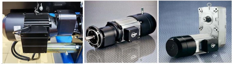
| Travel Motors | - Ex d flameproof housing - Temperature sensors with auto-shutdown |
- Power: 2×3-200kW - Speed: 10-60m/min (VFD controlled) |
| Ex Braking System | - Caliper brakes with Cu-Ni alloy pads - Fail-safe spring activation |
- Braking torque: 1.5×rated torque - Response time: <0.1s |
| Buffers | - Polyurethane with carbon filler (anti-static) - Oil dampers for heavy loads |
- Energy absorption: Up to 500kJ - Stroke: 150-400mm |
5. Operator Interface
| Component | Ex Rating | Features |
|---|---|---|
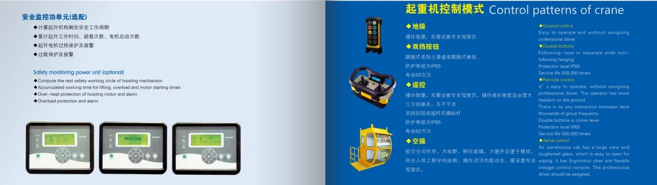
| Ex Pendant | - Ex e increased safety - Stainless steel buttons with O-ring seals |
- 8+2 button configuration - Emergency stop with mechanical lock |
| Wireless Remote | - Ex ia IIC T4 - Two-way communication with signal strength indicator |
- Range: 150m (LOS) - MTBF: >50,000 hours |
| Ex Cabin | - Pressurized (Ex px) with air purge system - Explosion-proof glass |
- Positive pressure: ≥50Pa - Air changes: 20×/hour |

6. Special Safety Systems
| Component | Function | Certification |
|---|---|---|
| Gas Detection | - Continuous monitoring of CH₄/H₂ concentrations - Auto-power cutoff at 20% LEL |
- SIL2 compliant - ATEX Cat 3G/3D |
| Static Discharge | - Copper grounding straps every 6m - Conductive wheel brushes (resistance <10Ω) |
- IEC 60079-32-1 |
| Fire Suppression | - NOVEC 1230 or CO₂ system integrated into girders | - NFPA 72/2001 compliant |
.

7. Optional Upgrades (European Standards)
Variable Frequency Drives (VFDs) – ABB/Siemens (smooth speed control).
Automation (IoT Sensors) – Predictive maintenance, remote monitoring.
Explosion-Proof (ATEX) – For hazardous zones.
Magnetic/Grab Attachments – For scrap, coils, bulk materials.

Why These Components Matter
Prevent Ignition Sources: Every electrical/mechanical element eliminates sparks, heat, or static
Zone-Specific Design: Components match the exact hazard classification (Gas Group IIC/IIB, T1-T6)
Fail-Safe Redundancy: Critical systems have backup circuits and mechanical overrides
For your specific application (oil/gas, chemicals, etc.), we can customize:
Gas Group (IIA/IIB/IIC)
Temperature Class (T1-T6)
Special Coatings (acid-resistant, cryogenic, etc.)
SKETCH

Main technical

Advantages
1. Superior Safety in Hazardous Areas
100% Spark-Free Operation: All components (motors, controls, brakes) meet ATEX/IECEx/NEC standards for Zone 1/21, Class I Div 1 environments.
Static Elimination: Conductive wheels, grounding straps, and anti-static coatings prevent static discharge.
Gas Detection Integration: Optional SIL2-rated sensors automatically shut down power if flammable gas reaches 20% LEL.
2. Heavy-Duty Performance
Unmatched Capacity: Handles 5–550 tons (vs. single girder's 1–20t) with ≤1/1000 girder deflection.
Precision Control: Ex-rated VFDs enable smooth speeds (0.5–15 m/min lifting, 5–60 m/min travel) even with delicate loads.
3. Extreme Environment Durability
Corrosion Resistance: Triple-layer epoxy coatings (300μm) withstand salt spray, H₂S, and acidic vapors.
Wide Temp Range: Operates at -40°C to +60°C with heated/cooled electrical enclosures.
4. Smart Maintenance Features
Predictive Monitoring: Vibration/temperature sensors transmit data via Ex-rated 4-20mA signals.
Modular Design: Tool-less access panels reduce downtime in Zone 2 maintenance areas.
5. Customizable Protection
Gas-Specific Configs: Components rated for IIA (propane), IIB (ethylene), or IIC (hydrogen).
Specialized Hoists: Choose between Ex d wire rope hoists (for heavy loads) or Ex e chain hoists (for precision).
Application:
| Industry | Typical Use Case | Hazard Mitigated | Ex Standard Applied |
|---|---|---|---|
| Oil & Gas | Offshore platform module installation | Methane (Group IIA) | ATEX Zone 1, IECEx Ex d IIA T3 |
| Chemical Plants | Chlorine cylinder handling | Hydrogen (Group IIC) | NEC Class I Div 1, Group B |
| Pharmaceutical | Solvent transfer in API production | Ethanol vapors (Group IIB) | ATEX Zone 1, Ex de IIB T4 |
| Mining | Coal mine shaft equipment maintenance | Methane + dust (Group I) | IECEx Ex d I M1 |
| Aerospace | Fuel tank assembly in paint booths | JP-8 fumes (Group IIB) | NFPA 496 (Purged Cabin) |
| Grain Silos | Bucket elevator maintenance | Wheat dust (Group IIIB) | ATEX Zone 21, Ex t IIIB |
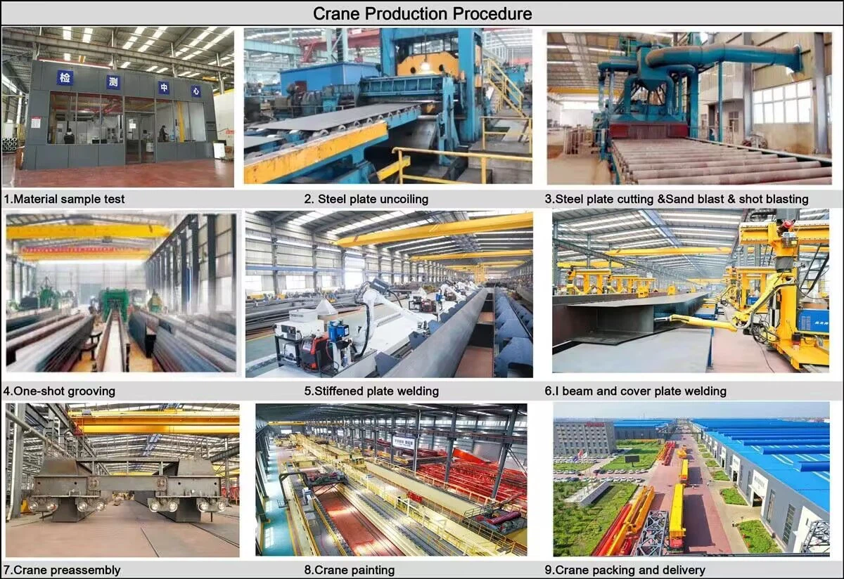
Crane production procedure
1.Design and Engineering
Requirements Gathering:
Load capacity (e.g., 10T, 50T, 100T, etc.), span, lifting height, and operational environment are defined.
Customization needs are assessed, such as control modes (pendant, wireless, cabin) and special features (e.g., anti-collision, overload protection).
Preliminary Design:
Structural engineers and crane designers create the crane's initial design, including the main beam, end carriage, lifting system, trolley system, travel mechanism, and other components.
Calculation and Simulation:
Load calculations are performed to ensure the crane can handle the specified capacity.
Finite element analysis (FEA) may be used to simulate stresses and deflections in the structure to ensure safety and stability.
Detailed Design:
After approval, detailed drawings for each part are made, including the main girder, end carriage, hoist system, motors, control systems, and safety features.
2. Material Procurement
Raw Material Selection:
High-quality materials like steel, alloyed steel, forged steel, and electrical components are sourced according to specifications.
Materials are inspected for quality certification and compliance with industry standards (e.g., ISO, CE).
Component Sourcing:
Standard components such as motors, hoists, control panels, limit switches, and safety devices are sourced from reliable suppliers.
3. Fabrication of Components
Main Girder:
Cutting and welding of steel plates to form the bridge girder.
The girder is assembled by welding or bolting sections, ensuring it meets the required strength and precision.
End Carriage Assembly:
The end carriage is fabricated and assembled to hold the crane on the runway rails.
Wheel assemblies are installed to ensure smooth travel along the rails.
Hoist and Trolley System:
The hoist unit (electric or manual) is assembled, including the drum, wire rope, hook, and motor.
The trolley system is built to transport the hoist across the bridge, including trolley wheels and drive mechanisms.
Crane Traveling Mechanism:
The crane wheels are mounted on the end carriages, ensuring smooth horizontal movement.
The drive system is installed to control travel speed.
4. Assembly of Crane
Main Beam Installation:
The assembled main girder is lifted and positioned onto the end carriages.
The girder is aligned to ensure structural integrity.
Trolley and Hoist Installation:
The trolley system is mounted onto the main girder, and the hoist is mounted to the trolley.
The load chain or wire rope is installed and tested for smooth operation.
Travel Mechanism Setup:
The crane wheels are fitted, and the drive mechanism is connected to the control system for horizontal movement.
5. Electrical and Control System Installation
Wiring and Control Panel:
The control panel is installed and wired to manage all crane movements (hoisting, trolley, crane travel).
Limit switches, emergency stop buttons, and safety alarms are integrated into the control system.
Motor and Gear Installation:
Motors for hoisting, traveling, and the trolley are installed and connected to their respective gear systems.
Testing of Control Systems:
Control systems are checked to ensure proper integration of pendant control, wireless remote, or cabin control options.
6. Testing and Quality Control
Load Testing:
The crane undergoes static load testing (to check stability) and dynamic load testing (to check operational performance under actual working conditions).
Overload protection and limit switches are tested to ensure they function correctly.
Safety System Testing:
The sound and light alarms, limit switches, emergency stop buttons, and safety devices are all tested for functionality.
Movement Testing:
All movements-hoisting, trolley movement, bridge travel, and sway control-are tested for smooth operation and precision.
Electrical Testing:
All electrical components are tested for proper wiring, grounding, and communication between systems.
Documentation and Certification:
The crane is inspected according to international safety standards and undergoes certification by relevant authorities (e.g., CE, ISO).
Test certificates for motors, cranes, and load testing are prepared.
7. Final Inspection and Painting
Visual Inspection:
A thorough inspection is carried out to ensure that the crane meets design specifications and safety requirements.
Painting:
The crane is painted with high-quality anti-corrosion coatings to protect it from environmental conditions.
Marking and Labeling:
Safety labels, warnings, and capacity markings are applied to the crane for proper identification.
8. Delivery and Installation
Shipping:
The crane is carefully disassembled into transportable parts (if needed) and shipped to the customer's location.
Installation:
The crane is installed on-site, and all connections (power, mechanical, control) are made.
Final Commissioning:
The crane is commissioned by running it through a series of operational tests to ensure it works properly.
Operator training is conducted, if necessary, for safe and efficient use.
9. Post-Installation Support
Customer Training:
Operator training on how to use the crane safely and effectively.
Maintenance Schedule:
Providing a maintenance plan for the crane's continued operation, including regular inspections, lubrication, and testing.
After-Sales Support:
Offering spare parts, troubleshooting, and repair services.
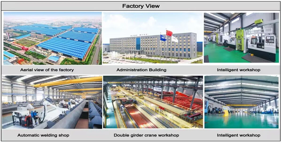
Workshop view:
The company has installed an intelligent equipment management platform, and has installed 310 sets (sets) of handling and welding robots. After the completion of the plan, there will be more than 500 sets (sets), and the equipment networking rate will reach 95%. 32 welding lines have been put into use, 50 are planned to be installed, and the automation rate of the entire product line has reached 85%.


Hot Tags: explosion-proof double girder overhead crane, China explosion-proof double girder overhead crane manufacturers, suppliers, factory, Double Girder Overhead Travelling Crane, Double Girder Overhead Crane
You Might Also Like


Send Inquiry