


Double Beam Grab Bucket Bridge Crane
Products Description
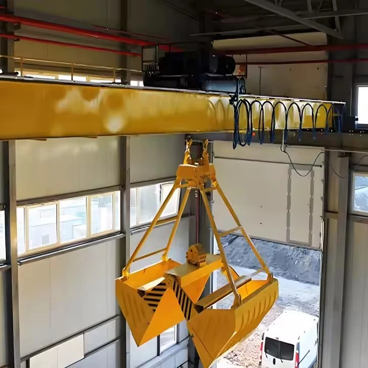
What Are Double Beam Grab Bucket Bridge Crane?
A Double Beam Grab Bucket Bridge Crane is an overhead crane with two main girders (beams) that runs on rails along a bridge spanning a bay or yard. It is equipped with a specialized grab bucket (also called a clamshell bucket) for handling bulk materials.
It's the workhorse for loose bulk solids in industries like ports, power plants, steel mills, and scrap yards.
Key Advantages
High Efficiency: Fully mechanized, fast cycling for large-volume transfer.
Versatility: One crane can serve multiple points (stockpile, transfer station, processing line).
Space Utilization: Uses overhead space, freeing up the ground for storage and vehicles.
Reduced Labor: Minimizes or eliminates the need for front-end loaders, excavators, and manual labor.
Enclosure Capability: Can be housed in a building or operated outdoors.
Design Considerations & Selection Factors
When specifying such a crane, engineers must consider:
| Factor | Considerations |
|---|---|
| Capacity | Weight of the grab + maximum weight of material lifted. (e.g., 10-ton crane with a 2-ton grab = 8-ton payload). |
| Span | Distance between the runway rails. Determines bridge design and cost. |
| Duty Class | How intensively it will be used (e.g., FEM/ISO M6, M7, or M8 for heavy-duty continuous operation). |
| Control System | Cab-operated (operator in a cab on the crane) or Radio Remote Control (operator on the ground). |
| Environment | Indoor, outdoor, corrosive (saltwater), explosive (coal dust), or high/low temperatures. |
| Grab Type & Size | Matched to material density, lump size, and abrasiveness. |
| Electrical Components | Variable Frequency Drives (VFDs) for smooth movement and precision. |
Summary
In essence, a Double Beam Grab Bucket Bridge Crane is a high-capacity, industrial-scale robotic arm on rails. Its double-beam design gives it the robustness for heavy loads and wide spans, while the grab bucket transforms it from a simple lifter into a precision bulk material handling system. It is a major capital investment designed to automate and streamline the core logistics of raw material movement.
Core Components:Bearing, Gearbox, Motor, Pump
Place of Origin:Henan, China
Warranty:1 Year
Weight (KG):2000 kg
Video outgoing-inspection:Provided
Machinery Test Report:Provided
Design:Double beam
Effectiveness:high efficiency
Operating speed:High speed operation
Stability:Anti-swing function
Color:Optional
Power Source:110V/220V/230V/380V/440V,customized
Span:7.5-31.5m

Pictures & Components
1. Bridge Structure & Long Travel System
This is the primary frame that moves the entire crane along the building or yard.
Main Girders (Double Beams): The two primary, parallel load-bearing beams. Typically robust box girders (welded steel boxes) for superior torsional stiffness and strength, capable of spanning large distances (30m to 100m+). They support the trolley, hoist, and the full load.
End Trucks: The wheeled assemblies at each end of the bridge girders. Each end truck contains:
Wheels (Travel Wheels): Two or more double-flanged steel wheels that ride on the runway rails.
Axles & Bearings: To support the wheels.
Drive Assembly (for driven end trucks): Includes the bridge drive motor, reduction gearbox, brake, and coupling to drive one or more wheels.
Bridge Drive: Usually 2 or 4 motors (one or two per end truck) for synchronized movement. Variable Frequency Drives (VFDs) are standard for smooth acceleration, precise positioning, and reduced mechanical stress.

2. Trolley & Cross Travel System
The unit that carries the hoist and travels perpendicular to the bridge motion.
Trolley Frame: A rigid steel frame that runs on rails mounted on top of the main girders.
Trolley Wheels & Rails: Wheels (usually 4 or 8) that run on trolley rails fastened to the top of the main girders.
Trolley Drive: Consists of drive motor(s), gearbox, brake, and drive wheels to move the trolley back and forth across the span of the crane.
Buffer & Bumper: Shock-absorbing devices at the ends of the trolley frame to prevent over-travel damage.
 |
 |
3. Hoisting & Grab Operating Mechanism
The heart of the lifting and grabbing function. For a grab bucket crane, this is more complex than a standard hook crane.
Main Hoist Unit: The primary winch for raising and lowering the grab.
Hoist Motor: High-torque, heavy-duty electric motor.
Hoist Gearbox: Reduces motor speed to achieve powerful lifting torque.
Hoist Drum: A large steel cylinder around which the hoist wire ropes are wound. The drum has machined grooves to guide the rope.
Hoist Brake: A failsafe, spring-applied, electrically released holding brake. It automatically engages if power is lost.
Rope Reeving: The specific arrangement of wire ropes from the drum, over sheaves (pulleys), down to the grab.
 |
 |
Grab Operating Mechanism: This differs based on grab type.
For a 4-Rope (Rope-Operated) Grab:
Auxiliary Hoist (Closing Hoist): A second, independent winch (with its own motor, gearbox, drum, and brake) dedicated to opening and closing the grab jaws. Its ropes are connected to the grab's closing mechanism.
For a Motorized Grab:
Power Cable Reel: A spring- or motor-driven cable reel supplies electricity down to the grab's internal motor via a pendant cable.
Grab Motor: The electric motor housed inside the grab's head, which directly drives the jaws via a gear train.

4. The Grab Bucket (Clamshell) Assembly
The specialized end-effector.
Head (or Shell): The central housing containing the hinge mechanism for the jaws. It has lifting lugs for connection to the hoist ropes.
Jaws (or Shells): The two (or sometimes more) hinged halves that dig into the material. They are very heavy and often lined with wear-resistant steel or hardfacing for abrasion resistance.
Hinge Pins & Bushings: Heavy-duty pins allowing the jaws to pivot.
For Motorized Grabs: Internal gearbox, motor, and linkage system to open/close jaws.
For Rope Grabs: Sheaves and linkages that translate rope pull into jaw movement.

5. Electrical & Control System
The nervous system and brain of the crane.
Main Power Supply:
Festoon System / Cable Reel: Delivers 3-phase AC power to the moving bridge. A cable reel or festoon (overhead sliding cable carrier) is used.
Main Circuit Breaker / Isolator: For safety and disconnect.
Control Cabin or Remote Control:
Operator's Cab: An enclosed, often air-conditioned cabin suspended from the trolley or bridge. Contains:
Remote Control System: More common today. The operator uses a radio remote control (pendant or belt-pack transmitter) for complete freedom of movement and visibility on the ground.

Control Panel / Cabinets: House the programmable logic controller (PLC), contactors, VFDs, and protective relays.
Command Devices: Master controllers or joysticks (usually two: one for bridge/trolley travel, one for hoist/grab operations).
Safety & Limit Devices:
Limit Switches: For end-of-travel on bridge, trolley, and hoist.
Anti-Collision Systems: Sensors to prevent cranes on the same runway from hitting each other.
Load Moment Indicator (LMI): Monitors load weight and provides anti-overload protection.
Anemometer: For outdoor cranes, measures wind speed and can trigger alarms or auto-shutdown.
Emergency Stop Buttons: Located at multiple strategic points.

6. Supporting Infrastructure
Critical, often fixed, components.
Runway System:
Runway Beams: Heavy steel I-beams or fabricated girders that support the crane rails. They are mounted on building columns or a separate gantry structure.
Crane Rails: Precision steel rails (like AISC or CR profiles) fixed to the runway beams for the crane wheels to run on.
Rail Clips & Fasteners: Secure the rail to the beam.

Collectors (for Cab-Operated Cranes):
Conductor Bars / Rails: Insulated electrified bars running along the runway.
Shoe Collectors: Spring-loaded shoes on the crane that slide along the conductor bars to pick up power for the bridge drive.

Sketch

Main technical

Advantages
1. Structural & Performance Advantages
High Load Capacity & Stability: Double beam design provides superior torsional rigidity and load distribution, enabling capacities from 5 to 500+ tons with minimal deflection
Long Span Capability: Can span 20-120 meters without intermediate supports, maximizing usable floor/yard space
Heavy-Duty Durability: Built for continuous operation (FEM/ISO M7-M8 duty classes) with 20-30+ year service life
Precision Control: Modern VFD drives allow smooth acceleration and precise positioning (±10mm accuracy)
2. Operational & Efficiency Benefits
Complete Material Handling Cycle: Single system performs pickup, transport, and discharge operations
High Throughput: Cycle times as low as 2-3 minutes (e.g., 25-ton grabs moving 500+ tons/hour)
Automation Ready: Easily integrated with PLC systems, RFID, and weighing systems for semi/full automation
Reduced Labor Costs: One operator replaces multiple front-end loaders and their operators
All-Weather Operation: Can operate in conditions where wheeled equipment fails (rain, snow, extreme temperatures)
3. Economic & Environmental Benefits
Lower Operating Cost: Electricity costs typically 40-60% less than diesel equipment per ton moved
Minimal Ground Footprint: Uses overhead space, keeping ground areas clear for storage and traffic
Reduced Spillage & Dust: Enclosed transfer points and controlled dumping minimize material loss and dust generation
Energy Recovery: Modern regenerative drives can feed braking energy back to the grid
Low Maintenance: Simple wheel/rail interface versus complex hydraulic systems in mobile equipment
4. Safety & Versatility
Inherently Safer: Separates man and machine; operator works from protected cab or safe distance
Multiple Grab Options: Quick-change systems allow different grabs for different materials
Adaptable Layout: Can serve multiple pickup and discharge points over large area
Disaster Resistant: Elevated design protects against floods and ground-level incidents
Application:
1. Energy Sector
| Application | Typical Materials | Special Features |
|---|---|---|
| Coal Handling (Power Plants) | Run-of-mine coal, washed coal | Dust-proof motors, fire-resistant coatings, automated blending systems |
| Biomass Plants | Wood chips, pellets, agro-waste | Corrosion protection, spark-resistant design |
| Waste-to-Energy | MSW, RDF, SRF | Sealed cabins with HEPA filtration, reinforced grabs for mixed waste |
2. Ports & Bulk Terminals
| Application | Scale | Configuration |
|---|---|---|
| Ship Unloading | 500-5,000 TPH | Gantry type with long outreach, ship positioning systems |
| Stockyard Management | 50,000-500,000 ton piles | Rail-mounted, stacking/reclaiming automation |
| Transshipment | Between vessels/trucks/rail | High-cycle duty, rapid grab changing |
3. Metals & Mining
| Application | Material Characteristics | Crane Requirements |
|---|---|---|
| Scrap Yards | Dense, abrasive, irregular | Heavy-duty grabs (5-50 ton), magnet options, reinforced structures |
| Ore Handling | High density, abrasive | Wear-resistant liners, high-capacity design (up to 100-ton grabs) |
| Slag Processing | Hot materials (up to 400°C) | Heat shields, special alloys, water-cooled components |
4. Building Materials & Chemicals
| Industry | Materials Handled | Special Considerations |
|---|---|---|
| Cement | Clinker, limestone, gypsum | Dust explosion protection, precision batching systems |
| Aggregates | Sand, gravel, crushed stone | Abrasion protection, high-volume handling |
| Fertilizers | Urea, potash, phosphates | Corrosion protection, moisture-sensitive handling |
| Grain & Food | Wheat, corn, soybeans | Food-grade standards, explosion-proof design |
5. Specialized Applications
Dam & River Management: Handling dredged materials, sediment removal
Disaster Response: Debris clearance, rapid material relocation
Recycling Facilities: Sorting and moving bulk recyclables
Foundries: Handling coke, sand, and castings
Crane production procedure
PHASE 1: ENGINEERING & DESIGN
1.1 Conceptual & Detailed Design
Client Specifications Review: Analysis of capacity, span, duty cycle, material handled, and environmental conditions.
CAD Modeling: 3D modeling (using software like SolidWorks, Tekla, or AutoCAD Inventor) of the entire crane system.
Structural Analysis: Finite Element Analysis (FEA) to simulate stresses, deflections, and dynamic loads on girders, end trucks, and trolley.
Mechanical & Electrical Design: Selection of motors, gearboxes, brakes, and design of control systems and wiring diagrams.
Bill of Materials (BOM) Generation: Comprehensive list of all raw materials, purchased components, and standard parts.
1.2 Procurement & Logistics
Raw Material Ordering: Procurement of steel plates (S355JR, Q345B), profiles, and forgings for main girders.
Purchased Components: Sourcing of standardized items (wheels, bearings, motors, gearboxes, VFDs, PLCs, wire ropes, electrical panels).
Grab Bucket Fabrication/Procurement: The grab may be built in-house as a specialized component or sourced from a dedicated grab manufacturer.
PHASE 2: MAJOR COMPONENT FABRICATION
2.1 Main Girder Fabrication (The Core Process)
This is the most critical fabrication activity, typically done on a dedicated production line.
Step 1: Steel Plate Preparation
Shot Blasting: Plates are cleaned and given a protective primer coat.
CNC Cutting: Plates are cut to exact shapes using CNC plasma or oxy-fuel cutting machines. Bevels for welding are prepared.
Step 2: Web & Flange Sub-Assembly
Stiffener Welding: Internal longitudinal and transverse stiffeners are welded to the web plate in a fixture to prevent buckling.
Flange Welding: The top and bottom flange plates are joined to the web assembly using submerged arc welding (SAW). This is done on automatic welding machines to ensure deep, consistent, high-strength welds.
Step 3: Box Girder Closure
The second web and flange are added to form the complete box section.
Sequential Welding: Welding is done in a specific sequence to control heat distortion.
Step 4: Stress Relieving & Straightening
Vibratory Stress Relieving or local heat treatment is often applied to relieve internal welding stresses.
Girder Straightening: Using hydraulic presses or flame straightening to correct any warping or camber deviation.
Step 5: Machining & Drilling
The ends of the girders are machined to ensure a perfect, square fit with the end truck connections.
Holes for connection bolts are drilled using a radial drill or CNC drilling machine for precision.
Step 6: Trolley Rail Mounting
The running surface for the trolley is meticulously aligned and welded or bolted to the top of the girder. Precision levels are used to ensure parallel alignment and flatness.
2.2 End Truck Fabrication
Frame Welding: Fabrication of the rigid end truck frames from steel plate.
Wheel Assembly: Press-fitting of wheels onto axles with heavy-duty bearings. The axle boxes are mounted to the frame.
Drive Unit Integration: The bridge drive motor, gearbox, and coupling are assembled onto the frame as a unit.
2.3 Trolley Frame Fabrication
Similar process to girder fabrication but on a smaller scale. Emphasis is on creating a rigid platform that will carry the hoist units.
Precise machining of the wheel base mounting points is critical for smooth travel.
2.4 Grab Bucket Fabrication
Cutting & Forming: High-wear areas (jaws, cutting edges) are cut from thick, abrasion-resistant steel (Hardox, AR400).
Assembly & Welding: Jaws are hinged to the head assembly. Welding here is critical and often uses manual Metal Inert Gas (MIG) welding for control.
Machining: Bushing holes and pivot points are machined for smooth operation.
Dynamic Balancing (for motorized grabs): The rotating assembly is balanced to minimize vibration.
PHASE 3: MECHANICAL ASSEMBLY & PAINTING
3.1 Pre-Assembly in Factory (Trial Fit-Up)
Girder-End Truck Connection: The two main girders are bolted to the end trucks to form the complete bridge. Alignment is checked with lasers.
Trolley Dry Fit: The trolley frame is placed on the girders to check fit and travel.
Purpose: To identify and correct any fit-up issues before disassembly for painting and shipment.
3.2 Surface Preparation & Painting
Abrasive Blasting: All components are blasted to Sa 2.5 standard to achieve a perfectly clean, anchor-profile surface.
Priming & Painting: Application of a multi-coat system:
Zinc-rich epoxy primer (75-100μm) for cathodic protection.
Epoxy intermediate coat (100-150μm) for build and chemical resistance.
Polyurethane topcoat (50-75μm) for UV resistance and final color.
Curing: Painted components are baked or air-cured in a controlled environment.
PHASE 4: ELECTRICAL & CONTROL SYSTEMS INTEGRATION
4.1 Panel Building
Control panels and resistor cabinets are wired according to schematic diagrams.
PLCs, VFDs, circuit breakers, and contactors are mounted and wired.
Software Programming: PLC logic is written, and VFD parameters are set for each motor (hoist, trolley, bridge).
4.2 On-Components Wiring
Motors, limit switches, push buttons, and sensors are wired on the mechanical assemblies.
Festoon Systems or cable reels are assembled.
All connections are tagged for easy installation on-site.
PHASE 5: FACTORY TESTING & INSPECTION (FAT)
Before shipment, critical tests are performed to ensure functionality and safety.
No-Load Functional Test: All motions (bridge, trolley, hoist, grab open/close) are operated to verify direction, speed, and brake function.
Load Testing (Mandatory Safety Test):
Static Load Test: Lifting 125% of rated capacity (per FEM/ISO standards) and holding it to check for structural integrity and brake holding.
Dynamic Load Test: Lifting and moving 110% of rated capacity to test all functions under overload conditions.
Safety Device Test: Verification of all limit switches, emergency stops, overload protection, and anti-collision systems.
Electrical Inspection: Insulation resistance checks, phase rotation verification, and grounding continuity tests.
PHASE 6: DISASSEMBLY, PACKING & SHIPPING
The crane is carefully disassembled into transportable modules (girders, end trucks, trolley, grab, electrical panels).
Components are packaged with wooden crates and protective coverings to prevent damage during sea/land transport.
Lifting lugs and detailed assembly drawings are marked on each piece.
PHASE 7: SITE ERECTION & COMMISSIONING (SAT)
Site Preparation: Verification of runway alignment, rail flatness, and electrical supply.
Mechanical Erection: Using mobile cranes, components are lifted and bolted together per assembly drawings.
Electrical Installation: All wiring is connected between panels, motors, and sensors.
Final Alignment & Adjustment: Wheel alignments, brake adjustments, and limit switch positioning.
Site Acceptance Test (SAT): A repeat of key FAT tests, but now on the installed runway, witnessed by the client. This is the final sign-off milestone.

Workshop view:
The company has installed an intelligent equipment management platform, and has installed 310 sets (sets) of handling and welding robots. After the completion of the plan, there will be more than 500 sets (sets), and the equipment networking rate will reach 95%. 32 welding lines have been put into use, 50 are planned to be installed, and the automation rate of the entire product line has reached 85%.


Hot Tags: double beam grab bucket bridge crane, China double beam grab bucket bridge crane manufacturers, suppliers, factory, Double Girder Overhead Crane, Double Girder Overhead Travelling Crane
You Might Also Like


Send Inquiry