










180T Bridge Beam Launcher For Highway Railway Girder Erection manufacturers

180T Bridge Beam Launcher For Highway Railway Girder Erection suppliers

180T Bridge Beam Launcher For Highway Railway Girder Erection factory

180T Bridge Beam Launcher For Highway Railway Girder Erection best

180T Bridge Beam Launcher For Highway Railway Girder Erection high quality
180T Bridge Beam Launcher For Highway Railway Girder Erection
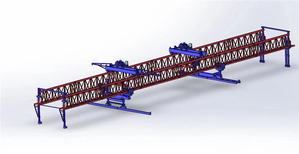
A 180T Bridge Beam Launcher (Girder Launcher) is a type of heavy construction equipment used in large-scale highway and railway bridge projects. It's also commonly called a launching gantry or bridge girder erection machine.

Core Function
The primary purpose of a 180ton bridge launcher is to lift, transport, and precisely place heavy prefabricated concrete or steel bridge components, typically weighing up to 180 tons (metric tons, ~165 US tons), during the construction of viaducts, overpasses, and highway bridges.
Key Design Parameters & Performance Specifications
| Parameter | Specification |
|---|---|
| Lifting Capacity (per girder) | 180 Metric Tons |
| Maximum Span (Pier to Pier) | 50 meters (Typical), customizable up to 60m |
| Minimum Curve Radius | 2,000 meters (can be designed for tighter radii) |
| Maximum Supported Grade | ±4% |
| Lifting Hoists | 2 x Main Hoists (typically 120-ton capacity each) |
| Hoist Lifting Speed | 0-5 m/min (variable speed control) |
| Trolley Traversing Speed | 0-10 m/min (variable speed control) |
| Main Beam Launching Speed | 0-5 m/min (variable speed control) |
| Machine Self-Propelling Speed | 0-5 m/min (variable speed control) |
| Control System | Centralized PLC with frequency control for all motions. Remote control operation. |
| Power Supply | 380V / 50Hz / 3 Phase (or as per project requirement) |

Pictures & Components
🏗️ 1. Main Structural Components
These form the body and load-bearing system of the launcher:
Main Girder (Launching Beam)
The long truss or box beam that spans between piers and carries the load.
Front Support Leg (Front Pier / Nose Support)
Positioned on the next pier; helps guide and stabilize during launching.
Middle Support Leg
Provides primary support and carries most of the load during erection.
Rear Support Leg
Supports the back end and helps balance the machine.
Launching Nose (Guide Girder)
A lighter extension at the front that helps the launcher move to the next span safely.
⚙️ 2. Lifting System
Responsible for handling the girders:
Lifting Trolleys (Crab Units)
Move along the main girder and carry the hoists.
Hoisting Winches
Lift and lower the girders (usually synchronized dual lifting points).
Wire Ropes / Hooks / Spreader Beams
Connect the hoist to the girder for safe lifting.
🚚 3. Traveling & Launching System
Allows the machine to move and reposition:
Longitudinal Traveling Mechanism
Moves the entire launcher forward span-by-span.
Transverse (Cross) Traveling Mechanism
Adjusts girder position sideways for precise alignment.
Wheel Assemblies / Rollers
Enable movement on rails or temporary tracks.
🔩 4. Support & Stabilization System
Bearing Supports / Saddles
Transfer loads safely to piers.
Outriggers / Stabilizers
Provide additional balance during lifting.
Temporary Supports
Used during installation or special conditions.
🔌 5. Power & Drive System
Electric Motors
Drive hoisting, traveling, and launching motions.
Gearboxes & Reducers
Control speed and torque.
Hydraulic System
Used for jacking, leveling, and adjustments.
🧠 6. Control System
Operator Cabin / Control Panel
Where the operator controls all functions.
PLC System (Programmable Logic Controller)
Automates and synchronizes operations.
Sensors & Limit Switches
Ensure safety and precise positioning.
🛑 7. Safety Systems
Overload Protection Devices
Emergency Stop System
Anti-sway & anti-collision devices
Wind speed monitoring system
🧩 8. Auxiliary Equipment
Cable reels & power supply system
Lighting system for night work
Maintenance platforms & ladders
Communication systems (radio/remote control)
🧠 Simple way to visualize it
Think of the launcher as a moving factory on top of the bridge:
The main girder = backbone
The trolleys & hoists = arms
The legs = support pillars
The motors & controls = brain and muscles

Sketch

Advantages
🚀 High efficiency & speed
Enables span-by-span erection without dismantling equipment
Reduces cycle time for each girder placement
Ideal for long viaducts and repetitive spans
👉 Result: Much faster project completion
🌉 Works in difficult environments
Operates above ground, so it doesn't depend on terrain below
Perfect for:
Rivers and deep valleys
Busy highways or rail lines
Urban or restricted sites
👉 No need for large ground cranes or access roads
🎯 High precision installation
Equipped with synchronized lifting and positioning systems
Allows accurate alignment of heavy girders
Minimizes installation errors and rework
👉 Critical for railway and high-speed rail projects
💰 Cost-effective over large projects
Reduces:
Crane rental costs
Temporary support structures
Labor requirements
👉 While initial investment is high, it saves money on long projects
🦺 Improved safety
Stable structure supported on bridge piers
Less lifting over open ground compared to cranes
Integrated safety systems (overload protection, anti-sway, etc.)
👉 Lower risk in complex erection conditions
🔄 Self-launching capability
Moves forward by itself from one span to the next
No need for dismantling and reassembly
👉 Saves significant time and labor
🔧 Versatility
Can handle:
Different girder lengths and weights
Straight, curved, and skew bridges
Suitable for both highway and railway applications
🌱 Reduced environmental impact
Minimal ground disturbance
Less need for temporary roads or heavy equipment below
👉 Better for sensitive environments
🧠 Bottom line
A 180T launcher is essentially a mobile, high-precision erection system that makes bridge construction:
Faster
Safer
More economical (at scale)
Less dependent on site conditions

Application
A 180T Bridge Beam Launcher is used wherever large bridge girders need to be installed efficiently and safely-especially in projects where traditional cranes are limited. Here are its main applications in real-world construction:
🌉 Highway bridge construction
Used for precast concrete girder erection on expressways and flyovers
Ideal for long elevated highways with repetitive spans
Common in urban flyovers where traffic below must continue
👉 Widely used in modern highway expansion projects
🚄 Railway & high-speed rail bridges
Essential for railway viaducts, including high-speed rail lines
Ensures high precision alignment, which is critical for rail safety
Handles heavy prestressed concrete girders used in rail systems
👉 A standard solution for high-speed rail infrastructure
🌁 Viaduct construction
Perfect for multi-span elevated structures across:
Valleys
Floodplains
Urban corridors
👉 Enables continuous span-by-span construction over long distances
🌊 Bridges over rivers & water bodies
Eliminates the need for:
Temporary scaffolding in water
Floating cranes or barges
👉 Especially useful where water conditions are difficult or deep
🏙️ Urban infrastructure projects
Used in metro, light rail, and elevated road systems
Minimizes disruption to:
Traffic
Buildings
Utilities
👉 Keeps cities functioning during construction
⛰️ Mountainous and difficult terrain
Suitable for areas where:
Ground access is limited
Heavy cranes cannot be deployed
👉 Common in hilly or remote regions
🔄 Bridge widening & rehabilitation
Can be adapted for:
Adding new girders to existing bridges
Replacing old beams
👉 Useful for upgrading infrastructure without full closure

Production Procedure
🔧 1. Design & Engineering
Confirm project requirements:
Lifting capacity (150T)
Beam length and type
Span and working conditions
Perform:
Structural analysis (strength & stability)
Load calculations and deflection checks
Finite Element Analysis (FEA)
👉 Output:
General Arrangement (GA) drawings
Detailed fabrication drawings
Assembly and installation plans
🔩 2. Raw Material Procurement & Inspection
Select high-grade steel (e.g., Q345B / Q420)
Inspect materials for:
Mechanical properties
Thickness and dimensional accuracy
Surface defects
👉 Only certified materials proceed to fabrication
🔨 3. Steel Structure Fabrication
Cutting & Forming
CNC flame/plasma cutting of plates and profiles
Precision bending and shaping
Welding
Submerged Arc Welding (SAW) for main truss beams
CO₂/MIG welding for secondary structures
Assembly
Fabrication of:
Main truss girders
Support legs
Cross beams
👉 Ensures high strength and dimensional accuracy
🔍 4. Welding Inspection (Quality Control)
Non-Destructive Testing (NDT):
Ultrasonic Testing (UT)
Magnetic Particle Testing (MT)
Visual Inspection (VT)
👉 Detects internal and surface defects
⚙️ 5. Machining & Precision Processing
Machining of:
Wheel assemblies
Bearing housings
Pin shafts and connection joints
👉 Ensures alignment, smooth movement, and durability
🧩 6. Component Manufacturing
Production of key systems:
Lifting winches and trolley
Hydraulic cylinders and piping
Support mechanisms
Spreader beams
👉 Each component tested individually before assembly
🔗 7. Pre-Assembly (Factory Trial Assembly)
Partial or full assembly in factory
Check:
Structural alignment
Bolt connections
Fit-up accuracy
👉 Ensures smooth on-site installation
⚡ 8. Electrical & Hydraulic System Installation
Install:
PLC control system
Motors, cables, sensors
Hydraulic pumps, valves, pipelines
👉 Includes insulation, grounding, and leakage testing
🎨 9. Surface Treatment & Painting
Shot blasting (Sa2.5 standard)
Anti-corrosion primer coating
Final paint layer (marine-grade optional)
👉 Protects against harsh outdoor environments
🧪 10. Testing & Commissioning (Factory)
Functional Testing
Hoisting system operation
Trolley and travel movement
Load Testing
Static load test (125% rated load)
Dynamic load test (110% rated load)
System Testing
Hydraulic synchronization
Electrical control accuracy
👉 Ensures compliance with international standards
📦 11. Disassembly, Packing & Delivery
Modular disassembly for transport
Packaging of:
Structural components
Mechanical systems
Electrical parts
👉 Suitable for container or bulk shipment
🏗️ 12. On-Site Installation & Commissioning
Assembly of truss structure and supports
Installation of mechanical and electrical systems
Final alignment and calibration
👉 Includes test run and operator training
🔒 Quality Control Highlights
Full compliance with ISO / FEM / EN standards
Complete inspection records and certificates
Traceability of materials and welds
Strict QA/QC procedures at every stage


Workshop View
The company has installed an intelligent equipment management platform, and has installed 310 sets (sets) of handling and welding robots. After the completion of the plan, there will be more than 500 sets (sets), and the equipment networking rate will reach 95%. 32 welding lines have been put into use, 50 are planned to be installed, and the automation rate of the entire product line has reached 85%.


Hot Tags: 180t bridge beam launcher for highway railway girder erection, China 180t bridge beam launcher for highway railway girder erection manufacturers, suppliers, factory
You Might Also Like


Send Inquiry