







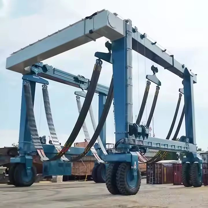
120 Ton Boat Hoist Crane
Products Description
What is a 120-Ton Boat Hoist Crane?
It is a heavy-duty lifting system with a maximum capacity of 120 short tons (or 240,000 lbs / ~109 metric tons). Its primary function is to vertically lift boats and yachts from the water. These are essential equipment for:
Marine Railways (boatyards)
Boat Manufacturers
Marinas serving large yachts
Government and Military Docking Facilities
Ship Repair Yards
Common Types of 120-Ton Boat Hoists
There are two main structural designs, each with its own advantages:
1. Mobile Gantry Crane (or Self-Propelled Boat Hoist)
This is the most common and versatile type for many boatyards.
Description: A large, wheeled steel frame that straddles the vessel. It moves on rails along a pier or a dedicated railway.
Operation: The crane is driven over the vessel in the water. Lifting straps (slings) are lowered and positioned under the hull. The crane then lifts the boat and transports it to a storage yard or work area.
Advantages:
High Maneuverability: Can service multiple slips and move boats around the yard efficiently.
Space Efficiency: Doesn't require a dedicated pit or permanent structure in the water.
Versatility: Can handle a wide range of boat sizes and shapes.
Disadvantages:
Requires a large, clear, and reinforced area of land for movement and storage.
The initial investment can be high.
2. Synchronous Marine Travelift® / Forklift-Style Hoist
This is a specific, well-known brand and style that functions like a massive forklift for boats.
Description: Features four large, independently steered tires, allowing for exceptional maneuverability (crabbing, tight turns).
Operation: Similar to a gantry crane, it drives over the vessel and uses a spreader bar with slings to lift the boat.
Advantages:
Excellent Maneuverability: Can operate in tighter spaces than a rail-bound gantry crane.
No Rails Needed: More flexible for yard layout changes.
Disadvantages:
Requires a very strong and level yard surface to support the immense point loads.
Generally has a higher ground pressure than a rail-bound gantry.
(Note: "Travelift" is a trademarked name of Marine Travelift, but is often used generically for this style of hoist.)
Comparison with Other Boat Lifting Systems
| Feature | Gantry Boat Hoist | Marine Railway | Floating Dry Dock |
|---|---|---|---|
| Mobility | High (if rubber-tired) | Low (fixed track) | Low (water-dependent) |
| Max Capacity | 10–500+ tons | 50–5,000 tons | 1,000–100,000+ tons |
| Speed | Fast (minutes) | Slow (hours) | Moderate (hours) |
| Best For | Small to medium boats | Large ships | Massive vessels |
Comparison with Other Boat Lifting Systems
| Feature | Gantry Boat Hoist | Marine Railway | Floating Dry Dock |
|---|---|---|---|
| Mobility | ✅ High (if rubber-tired) | ❌ Fixed track | ❌ Water-dependent |
| Max Capacity | 10–500+ tons | 50–5,000 tons | 1,000–100,000+ tons |
| Speed | ⚡ Fast (minutes) | 🐢 Slow (hours) | 🕒 Moderate (hours) |
| Space Needed | Compact storage | Long track area | Large water area |
| Best For | Small-medium boats | Large ships | Massive vessels |
Lifting Capacity 120 tons
Span (Width) 3 - 12 meters (adjustable)
Lifting Height 3 - 10 meters
Working Class A3-A5 (light to medium duty)
Hoisting Speed 0.5 - 8 m/min (variable)
Main Beam Type Single/double girder (box-type)
Power Supply 220V/380V 3-phase or manual
Control Mode Pendant control/wireless remote
Hoist Type Electric chain hoist/wire rope hoist
Travel Drive Manual push or motorized
Corrosion Protection Hot-dip galvanized or marine-grade paint
Wind Resistance Up to Beaufort scale 6 (for outdoor use)
Operating Temp -20°C to +50°C

Pictures & Components
I. Structural Components (The Frame & Support)
These parts form the primary load-bearing structure.
Main Beams (Longitudinal Girders): These are the two massive, horizontal beams that run the length of the crane, spanning the width of the boat. They are designed to resist extreme bending moments from the lifted load.
End Frames / Legs: The vertical structures at each end of the main beams. They house the lifting mechanisms and provide the clearance needed for the vessel.
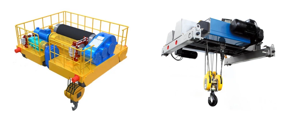
Cross Members: Structural elements that connect the two main beams, ensuring the entire structure remains rigid and square.
Spreader Bars: Used to distribute the load from the slings to multiple lifting points on the main beams, preventing excessive point loads.

II. Lifting and Load-Handling Components
This system is responsible for actually raising and lowering the boat.
Wire Rope Hoists: The primary lifting devices. A 120-ton crane would typically have four independent hoists (one at each leg), synchronized electronically.
Wire Ropes (Cables): High-strength, steel cables wound on drums.
Hoist Drums: Large, cylindrical drums around which the wire rope is spooled. Driven by electric or hydraulic motors.
Gearboxes and Brakes: Reduce motor speed to provide high torque and include failsafe braking systems to hold the load.
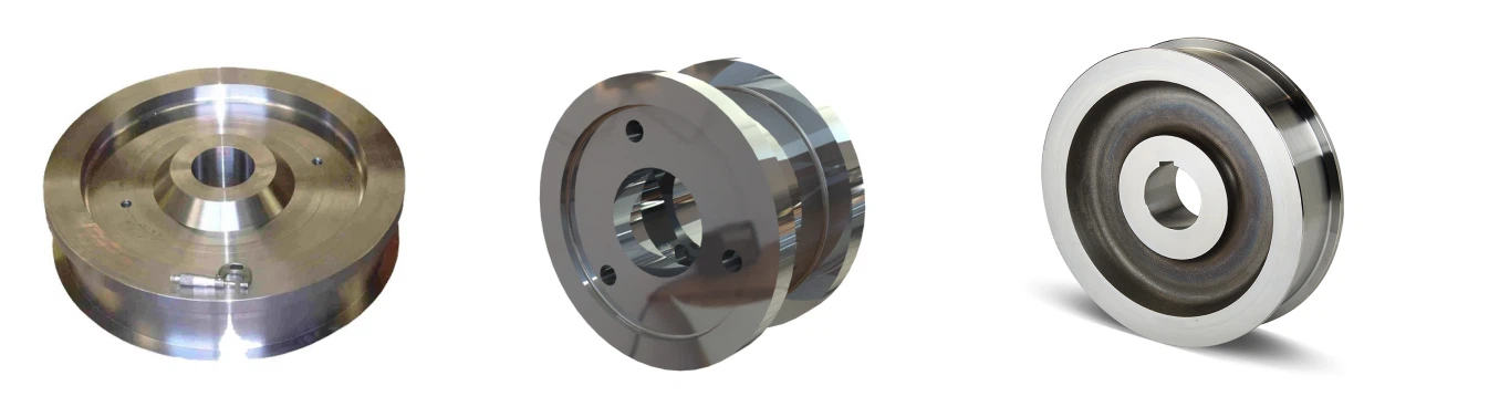
Load Blocks: The assemblies of pulleys (sheaves) that the wire rope is threaded through. They provide mechanical advantage and guide the rope.
Upper Blocks: Fixed to the main beams.
Lower Blocks (Hook Blocks): The movable blocks to which the slings are attached. They contain multiple sheaves to increase the crane's lifting capacity.
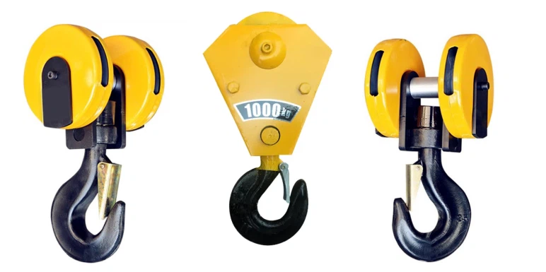
Lifting Slings: The wide, flexible straps that cradle the boat. For a 120-ton capacity, these are extremely heavy-duty, often made of high-tenacity polyester or nylon to protect the boat's hull.
Spreader Bars for Slings: Often used to keep the slings apart and ensure they contact the hull at the proper, reinforced lifting points (straps).


III. Power and Drive System (Mobility)
This is what makes the crane mobile and self-propelled.
Power Unit / Engine: A large diesel engine (or sometimes an electric power pack) that generates hydraulic pressure and/or electrical power for all crane functions.
Hydraulic System:
Hydraulic Pumps: Driven by the engine to create high-pressure fluid flow.
Hydraulic Motors: Power the wheel drives and the hoists.
Hydraulic Cylinders: Used for steering and possibly for minor adjustments.
Reservoirs, Valves, and Hoses: The circulatory system for the hydraulic fluid.
Drivetrain:
Wheel Modules: Each wheel is typically independently driven and steered. A 120-ton crane will have multiple axles (e.g., 4 or more per side) to distribute the ground pressure.
Tires: Wide, high-capacity, pneumatic tir

IV. Control and Instrumentation System
The "brain" of the crane, ensuring safe and precise operation.
Operator's Cabin: An elevated, climate-controlled cabin located on one of the end frames, giving the operator a clear view of the load.
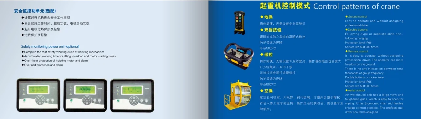
Main Control Console: Contains joysticks, switches, and touchscreens for controlling travel, steering, lifting, and lowering.
Load Moment Indicator (LMI) System: A critical safety system that monitors the load in real-time.
Load Cells: Sensors installed in the hoists or on the hooks that measure the actual weight on each leg.
Angle Sensors: Monitor the boom angle or the hoist rope angle.
Computer/Display: Calculates and displays the total weight, weight on each leg, and warns the operator if they are approaching or exceeding the crane's rated capacity.
Synchronization System: Electronically synchronizes the four hoists to ensure the boat is lifted level, preventing dangerous structural stresses.
V. Safety Components
Non-negotiable features to protect personnel, the boat, and the equipment.
Emergency Stop Buttons: Located at multiple points on the crane, including the cabin and ground-level panels.
Overload Protection: Part of the LMI system, it will automatically cut out lifting functions if a preset safety limit is exceeded.
Limit Switches: Prevent the hoists from over-traveling at the top and bottom of their range.
Anemometer: Measures wind speed. Lifting operations are often restricted above a certain wind speed.
Audible and Visual Alarms: Horns and flashing lights to warn personnel when the crane is about to move or lift.
Chocks and Jackstands: While not part of the crane itself, these are essential supporting components placed under the boat once it is lifted to transfer the load from the crane slings to a stable support structure.
Summary Workflow:
The crane is driven over the vessel in the water.
Slings are lowered into the water on each side of the hull.
The crane is positioned so the slings are under the boat's reinforced lifting points.
The operator uses the synchronized hoists to slowly and evenly tension the slings.
The LMI system confirms the load is balanced and within capacity.
The boat is lifted clear of the water.
The crane transports the boat to a designated land location.
The boat is carefully lowered onto jackstands, the slings are loosened, and the crane drives away.
Applications of Each Component
| Component | Function |
|---|---|
| Gantry Frame | Supports entire structure |
| Winches & Slings | Lifts the boat |
| Trolley System | Positions boat over storage area |
| Steering Mechanism | Allows precise maneuvering |
| Load Sensors | Ensures safe lifting capacity |
SKETCH
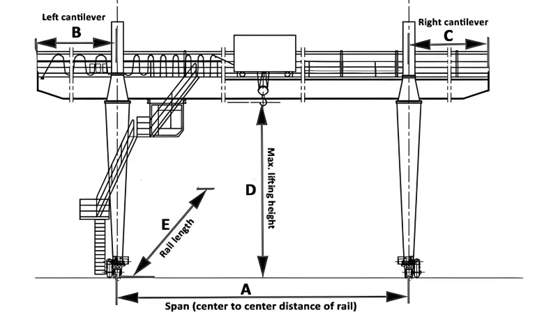
Main technical
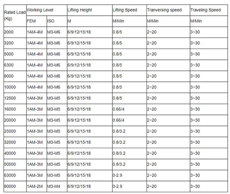
Advantages
1. Unmatched Versatility and Flexibility
Wide Range of Vessels: A 120-ton capacity can handle a vast array of boats, including large yachts, fishing vessels, patrol boats, crew transfer vessels, and commercial barges. It's a versatile "sweet spot" for many marine operations.
Multiple Slip Usage: Unlike a fixed railway system, the crane can be moved (typically on rails) to service multiple slips or work areas. This allows one crane to serve many boat storage positions efficiently.
Individual Boat Handling: You can lift a single boat without needing to move others that are stored in front of it, which is a common limitation with railway systems.
2. Superior Space Efficiency and Land Utilization
High-Density Storage: The primary advantage is the ability to store boats in multiple rows, both in the water and on land ("stacked" storage). This maximizes the use of expensive waterfront real estate.
Reduced Footprint: Compared to a travel lift with a large, fixed corridor, a gantry crane's structure is overhead, allowing for more flexible use of the ground space beneath it for parking, workshops, or other storage.
3. Operational Speed and Efficiency
Fast Lift and Launch Cycles: The process of lifting a boat from the water, transporting it to a storage yard, and setting it down is very quick. This allows a yard to service a high volume of boats, especially during busy seasons like spring launch and winter haul-out.
Quick Turnaround for Repairs: For short-duration work like bottom painting, propeller repair, or transducer replacement, a boat can be lifted, worked on, and relaunched in a matter of hours, maximizing yard productivity.
4. Enhanced Safety and Control
Stable and Secure Lifting: Modern boat hoist cranes use sophisticated, synchronized hoists and spreader bars with multiple adjustable straps. This provides a balanced and secure lift, minimizing stress on the boat's hull.
Precise Maneuvering: Operators have excellent control over the boat's movement, allowing for precise placement in tight storage spaces. This reduces the risk of accidental damage to the lifted boat or surrounding property.
All-Weather Operation: These cranes are designed to operate safely in various weather conditions, unlike some alternatives that may be more susceptible to wind or waves.
5. Economic Advantages
High Return on Investment (ROI): While the initial capital cost is high, the ability to handle more boats faster and utilize land more efficiently leads to a strong ROI for busy boatyards.
Reduced Labor Requirements: A single crane operator and a small ground crew can efficiently move boats, reducing labor costs compared to more manual methods.
Attracts Larger Clients: Having a 120-ton capacity allows a marina or boatyard to attract and service larger, more valuable vessels, which typically command higher service fees.
6. Minimal Environmental Impact
No Bottom Disturbance: Unlike a railway system that requires dredging to maintain the track bed, a crane lifts the boat clear of the water, causing no disturbance to the seabed or shoreline.
Containment of Work: Maintenance work (like sandblasting and painting) can be done in a designated, contained area, preventing pollutants from entering the water.
Application
Key Applications and Use Cases
1. Boat Yard Operations (Most Common)
Winterization and Storage: Lifting boats for long-term winter storage on land, protecting them from ice and harsh marine conditions.
Bottom Maintenance: Essential for tasks like:
Hull Cleaning: Removing marine growth (algae, barnacles).
Antifouling Paint: Applying new coats of bottom paint to prevent future growth.
Inspections: Thoroughly inspecting the hull, rudder, propeller, and through-hull fittings for damage, corrosion, or wear.
Repair and Refit: Facilitating major structural repairs, engine replacements, or system upgrades that require dry-dock conditions.
2. New Construction and Launching
In shipyards and boat manufacturers, the crane is used to move large hull sections, install heavy components (like engines), and for the final launch of newly built vessels into the water.
3. Emergency Services
Salvage Operations: Quickly lifting vessels that have sunk, run aground, or are taking on water to prevent further damage or environmental hazards.
Rapid Haul-out: Removing a boat from the water urgently to address catastrophic failures like a severe hull breach.
4. Transport and Relocation
Moving boats from storage racks to the water and back again, optimizing space within a crowded boatyard. It can also load/unload boats from trailers or trucks for transport over the road.
Crane production process
Phase 1: Engineering & Design
This is the most critical phase, where the crane's capabilities and safety are defined.
Client Requirements Analysis:
Lifting Capacity: 120 tons (often with a lower-rated auxiliary hoist for smaller lifts).
Span: The distance between the crane's legs, determined by the width of the dry dock or travel path.
Lifting Height: How high the boat needs to be lifted.
Operational Environment: Marine (corrosive), seismic zone, wind conditions.
Mobility: Will it be a fixed gantry, a rail-mounted gantry, or a rubber-tired portal crane?
Structural Design & Calculations:
CAD Modeling: 3D models are created for the entire structure (main girders, end carriages, legs).
Finite Element Analysis (FEA): Software simulates stresses, deflections, and dynamic loads to ensure structural integrity under worst-case scenarios (e.g., full load plus high winds). This validates the design before any steel is cut.
Load Chart Development: Defining safe working loads at various boom radii or hook positions.
Mechanical & Electrical System Design:
Hoist Mechanism: Selection and integration of the main hoist (wire rope, drum, motor, gearbox, and brakes). For a 120-ton crane, multiple falls of rope are used to share the load.
Trolley System: Design of the system that moves the hoist along the main bridge girder.
Travel System: Design of the drive units, wheels, and axles for moving the entire crane. This includes powerful motors and fail-safe brakes.
Power System: Design of the electrical cabinet, conductor bars (or festoon systems), and motors. Often 480V AC industrial power.
Control System: Design of the operator's cabin (with full visibility) and radio remote control system.
Regulatory Compliance:
Designs are made to comply with international standards such as FEM 1.001 (European standard for cranes), ISO 4301 (Cranes - Classification), and CMAA (Crane Manufacturers Association of America) specifications.
Phase 2: Material Procurement & Fabrication
This phase transforms raw materials into finished components.
Material Procurement:
Steel: High-quality structural steel plates (e.g., S355J2) and rolled sections (I-beams, channels) are sourced. Certificates of conformity for the steel's grade and properties are mandatory.
Purchased Components: Critical components are procured from specialized suppliers:
Hoist Unit: Often a certified, off-the-shelf unit from a reputable hoist manufacturer.
Electrics: Motors, variable frequency drives (VFDs for smooth control), brakes, and sensors.
Wheels, Axles, and Bearings: High-capacity, forged steel components.
Wire Rope, Hooks, and Shackles: All certified for the 120-ton load.
Fabrication Process:
CNC Cutting: Steel plates are cut to precise shapes using CNC plasma or oxy-fuel cutting machines.
Drilling and Machining: Holes for high-strength bolts are precision-drilled. Bearing seats and other critical surfaces are machined.
Forming: Steel plates may be rolled or pressed into curved sections.
Welding (The most critical fabrication step):
Jigging: Components are clamped in large jigs to ensure perfect alignment.
Sub-Assembly Welding: Smaller parts are welded together (e.g., stiffeners to a web plate).
Main Assembly Welding: Major components like the main girders are welded. This is done by certified welders using procedures qualified for the specific steel grade.
Non-Destructive Testing (NDT): Welds are inspected using methods like Magnetic Particle Testing (MT) or Ultrasonic Testing (UT) to detect internal flaws. 100% of critical welds are tested.
Surface Preparation & Painting:
Abrasive Blasting: The entire structure is shot-blasted to remove mill scale and rust, creating a surface profile for paint adhesion.
Priming: A high-quality, zinc-rich epoxy primer is applied for corrosion protection.
Top Coating: Polyurethane topcoats are applied in the specified color. For marine environments, a multi-coat system is essential.
Phase 3: Assembly & Integration
Components are brought together to form the complete crane.
Sub-Assembly:
The end carriages (legs with travel mechanisms) are assembled.
The main bridge girders are assembled, often in two halves for large spans.
The trolley frame is built, and the hoist unit is mounted onto it.
Major Assembly (often done at the manufacturer's facility for a trial fit-up):
The main girders are bolted or welded to the end carriages.
The trolley and hoist are placed on the bridge rails.
The electrical cabinets, conductor bars, and control systems are installed.
The operator's cabin is mounted.
Electrical Integration:
All motors, sensors, and controls are wired.
The programmable logic controller (PLC) is installed and the initial software is loaded.
Limit switches (for hook height, trolley travel, and crane travel) are positioned and tested.
Phase 4: Testing, Certification, & Delivery
The crane is rigorously tested to ensure it is safe and performs as designed.
Factory Acceptance Test (FAT): If possible, the crane is partially assembled at the factory for a preliminary test of functions (movement, limits) without the full load.
Disassembly & Shipping:
The crane is carefully disassembled into transportable sections (girders, legs, mechanical components).
Components are crated and shipped to the customer's site.
Site Erection:
A team of erectors assembles the crane on-site, following precise engineering drawings. This involves:
Preparing the foundation/rails.
Erecting the end carriages.
Lifting the main girders into place (often using a mobile crane).
Reassembling the trolley and hoist.
Connecting all electrical systems.
On-Site Testing & Certification:
No-Load Test: All crane functions are tested without a load to check for smooth operation, correct direction of movement, and functionality of limit switches.
Load Test (The most important step):
Static Load Test: The hoist is lifted with a test load 25% greater than the rated capacity (i.e., 150 tons). The load is held suspended for a period to check the structure for permanent deflection and the brakes for holding capability.
Dynamic Load Test: The crane is operated with a test load 10% greater than the rated capacity (i.e., 132 tons). It is run through all motions (hoisting, trolley travel, crane travel) to ensure performance under dynamic stresses.
Measurements are taken to confirm girder deflection is within calculated limits.
Final Certification:
A third-party inspector (e.g., Lloyd's Register, DNV, or a local government inspector) often witnesses the load tests.
Upon successful completion, a Certificate of Test and Compliance is issued, legally permitting the crane to be put into service.
Operator Training & Handover:
The manufacturer provides comprehensive training for the client's maintenance and operations staff.
Final documentation, including operation manuals, maintenance schedules, and as-built drawings, is handed over.
This entire process, from initial design to final handover, can take several months to a year, depending on the complexity and customization of the 120-ton boat hoist crane.

Workshop view:
The company has installed an intelligent equipment management platform, and has installed 310 sets (sets) of handling and welding robots. After the completion of the plan, there will be more than 500 sets (sets), and the equipment networking rate will reach 95%. 32 welding lines have been put into use, 50 are planned to be installed, and the automation rate of the entire product line has reached 85%.




Hot Tags: 120 ton boat hoist crane, China 120 ton boat hoist crane manufacturers, suppliers, factory
You Might Also Like


Send Inquiry