










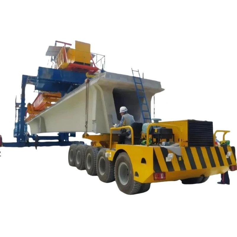
150ton Hydraulic Precast Bridge Beam Transporter
a 150-ton Hydraulic Precast Bridge Beam Transporter, also commonly known as a Self-Propelled Modular Transporter (SPMT) or a Bridge Beam Transporter/Gantry.
This machine is a highly specialized piece of heavy-duty equipment designed for one of the most critical tasks in bridge construction: moving the massive precast concrete or pre-stressed girders from the casting yard to their final position on the bridge piers.

Key Features
A 150-ton beam transporter is a specialized, self-propelled modular transporter (SPMT) designed for the precise and safe handling of extremely heavy and long precast concrete or pre-stressed girders used in bridge construction.
I. Core Lifting and Load-Bearing Features
High-Capacity Hydraulic System: The heart of the machine, featuring multiple hydraulic pumps and cylinders that provide the immense force needed to lift, lower, and adjust the 150-ton load smoothly and controllably.
Multi-Point Synchronized Lifting: The transporter has several lifting points (e.g., four or more) under the beam. These points are electronically synchronized to ensure the beam is lifted and lowered evenly, preventing dangerous twisting or bending stresses on the precast concrete.
Modular & Adjustable Deck / Support Beams: The deck consists of strong, modular beams that can be adjusted in width and length to accommodate different sizes and types of bridge beams (I-beams, box girders, etc.).
Heavy-Duty Hydraulic Suspension: Each axle line is equipped with independent hydraulic suspension that can compensate for uneven ground, ensuring the load remains level and stable during transport.
II. Mobility and Maneuverability Features
All-Wheel Steering (AWS): This is a critical feature. Each set of wheels can be steered independently, allowing for a variety of movement patterns:
Crab Steering: All wheels turn in the same direction, enabling the transporter to move diagonally.
Coordinated Steering: Front and rear wheels turn in opposite directions, allowing for a very tight turning radius, essential for navigating confined construction sites.
360-Degree On-the-Spot Rotation: The entire platform can rotate around its own center.
Self-Propelled Operation: Powered by a robust diesel engine or an electric motor, the transporter moves under its own power with precise speed control, eliminating the need for a separate prime mover.
Multi-Axle Configuration: The weight is distributed over a large number of wheels (e.g., 4, 6, or 8 axle lines) to reduce ground pressure and meet road weight regulations when moving on-site.
Precise Speed Control: Features creep mode or micro-speed control for millimeter-accurate positioning when setting the beam onto the bridge piers.
III. Control and Safety Features
Centralized Computerized Control System: The operator controls the entire machine from a remote control panel (pendant) or a cabin. The computer manages all functions, including steering, lifting, and speed, ensuring synchronization and safety.
Load Moment Indicator (LMI) System: Continuously monitors the weight on each lifting point and the overall stability of the load. It provides warnings and will automatically shut down if it detects an unsafe condition.
Fail-Safe Braking System: Redundant hydraulic and mechanical braking systems that engage automatically in case of a power failure or hydraulic pressure loss.
Emergency Stop Buttons: Located at multiple points on the machine and on the remote control for immediate shutdown.
Outrigger Stabilizers: Hydraulic outriggers can be extended to provide a stable base during the lifting and final positioning phases, preventing any tipping.
IV. Operational and Practical Features
Robust Frame Construction: Built from high-tensile steel to withstand the immense stresses of daily heavy lifting without deformation.
Anti-Slip Deck Surface: The deck has a patterned or coated surface to prevent the beam from shifting during transport.
Integration with Beam Lifting Devices: Designed to work seamlessly with specialized lifting hardware, such as hydraulic lifting beams or strongbacks, which help distribute the lifting force evenly along the precast girder.
Weather Resistance: Key components are sealed and protected to allow for reliable operation in various weather conditions common on construction sites.

Parts & Components
1. Structural Framework
This is the core physical structure that bears the load.
Main Deck/Platform: A heavy-duty, steel fabricated platform that provides the surface on which the precast beam rests. It is designed with high rigidity to prevent bending under the extreme load.
Support Beams/Cradles: Customizable, adjustable supports or cradles mounted on the deck. These are contoured or padded to securely hold the specific shape of the bridge beam (e.g., I-beam, U-beam, box girder) and distribute the load evenly.
Modular Units: SPMTs are often modular. Multiple 4-axle, 6-axle, or 8-axle modules can be connected side-by-side and end-to-end using:
Pin Connectors: High-strength steel pins that lock modules together mechanically, allowing them to act as a single, wider platform.
2. Power Module & Control System
The "brain" and "heart" of the transporter.
Power Pack (Diesel or Electric): A dedicated diesel engine or an electric motor-driven power unit that generates hydraulic pressure and electrical power for the entire system. For a 150-ton capacity, this is a significant unit.
Centralized Electronic Control System: The operator uses a remote control (often a pendant or wireless remote) to command the transporter.
On-Board Computers (ECUs): Each axle module has an Electronic Control Unit that receives signals from the main controller and precisely manages the hydraulic functions of its assigned axles and suspension.
3. Hydraulic System
This system provides the lifting, steering, and propulsion capabilities.
Hydraulic Suspension Cylinders: Located on each axle line, these cylinders allow for independent lifting and lowering of the deck. This is critical for:
Load Balancing: Distributing the beam's weight evenly across all axles.
Negating Ground Slope: Keeping the beam level even on uneven terrain.
Jacking Function: Raising the beam slightly to clear temporary supports.
Hydraulic Steering Cylinders: Enable each axle set to be steered independently. This allows for a wide range of movements:
Standard Steering: Like a truck.
Crab Steering: All wheels turning in the same direction for sideways movement.
Circular Steering: Rotating the entire transporter around a central point.
Diagonal Steering: For complex maneuvers in tight spaces.
Hydraulic Drive Motors: Power the wheels. Not all SPMTs are driven; some are pushed/pulled by a separate tractor. A self-propelled 150-ton transporter would have powerful hydraulic motors on several axles.
4. Axle and Wheel System
The interface between the machine and the ground.
Axle Lines: Each axle line consists of a solid or fabricated steel beam with wheels on both ends. A 150-ton transporter would typically be configured from multiple modules, each with 2 to 4 axle lines.
Pendulum Axles: The axles are often mounted on pendulum arms, allowing them to pivot and maintain full ground contact even on uneven surfaces, ensuring the load is distributed safely.
Wheels and Tires: Heavy-duty, solid or pneumatic tires rated for extreme loads. The number of tires is a direct function of the ground bearing pressure.
5. Safety and Ancillary Components
Essential for secure and reliable operation.
Outriggers/Stabilizing Legs: Hydraulic legs that can be extended to the ground to provide additional stability when the transporter is stationary or during the loading/unloading process.
Load Sensing System: Monitors the pressure in each hydraulic suspension cylinder, providing real-time data on the weight distribution and total load to the operator and control system.
Safety Locks/Mechanical Stops: Physical locks that can be engaged to secure the hydraulic suspension cylinders, providing a mechanical failsafe in case of hydraulic failure.
Anti-Collision Sensors: Proximity sensors or laser scanners that can detect obstacles and automatically stop the vehicle to prevent accidents.
Tie-Down Points: Robust points on the deck for securing the beam with high-strength chains or straps during transport (though the beam's weight is primarily held by friction and the cradles).
How the Components Work Together to Transport a Beam:
Positioning: The transporter is driven or positioned underneath the beam, which is supported on temporary piers or a casting bed.
Lifting: The operator uses the remote control to raise the hydraulic suspension cylinders, gently lifting the beam off its supports. The load sensing system ensures the weight is even.
Securing: The beam is secured within the adjustable cradles. Outriggers may be extended for stability.
Transport: The operator selects the appropriate steering mode (e.g., crab steer to move sideways out of the casting yard) and drives the transporter along a pre-planned route at very low speeds (typically 1-3 km/h).
Placing: Upon reaching the bridge abutments or piers, the transporter maneuvers with extreme precision. The hydraulic suspension allows for micro-adjustments in height and levelness to place the beam exactly into its final position on the bearing pads.
Lowering & Retracting: The beam is lowered onto its permanent supports, the transporter is lowered, and it then drives out from underneath the beam to pick up the next one.
In summary, a 150-ton precast beam transporter is a symphony of heavy-duty structural engineering, precise hydraulic control, and intelligent electronics, all working in unison to handle one of the most critical and heavy components in bridge construction.

Product Parameter

Sketch

Advantages
1. Superior Precision and Control
This is the single greatest advantage. The transporter uses multiple synchronized hydraulic systems (lifting, steering, traversing) that allow for millimeter-accurate positioning.
Micro-Movements: Operators can inch the beam forward, backward, sideways, and even rotate it slightly while it is suspended. This is crucial for aligning the beam's ends perfectly with the bearing pads on the bridge piers.
Eliminates "Swing": Unlike a crane-slung load that can swing in the wind, the beam is securely cradled by the transporter, allowing for safe and precise work even in moderate wind conditions.
2. Enhanced Safety
Moving a 150-ton object is inherently hazardous. The transporter significantly mitigates these risks.
Stability: The machine has a very low center of gravity and a wide wheelbase, making it extremely stable and resistant to tipping.
Controlled Environment: The entire operation is controlled from a single cabin, often with remote-control options, keeping personnel at a safe distance.
Reduced Crane-Related Risks: It eliminates the need for two large cranes working in tandem ("dual-lift"), which is a complex and high-risk operation requiring perfect communication and coordination.
3. High Efficiency and Speed
For projects requiring the placement of multiple beams, the transporter is vastly more efficient.
Rapid Cycle Times: Once the first beam is placed, the transporter can quickly drive back, pick up the next beam, and position it without the need to reposition large cranes.
No Crane Setup/Tear Down: Cranes require extensive time for assembly, ballasting, and disassembly. The transporter is a self-contained unit that can be ready to work much faster.
Continuous Workflow: It creates a more streamlined, assembly-line-like process from the casting yard to the final placement.
4. Maneuverability and Access in Confined Spaces
This is a key advantage in challenging site conditions.
Multi-Axle Steering: These transporters often have 8, 10, or more axles, all of which can be independently steered. This allows for incredible maneuverability, including:
Crab Steering: Moving diagonally.
Circle Steering: Rotating around the center of the load.
Tight Turns: Navigating around obstacles and through tight spaces on the construction site.
Ability to Traverse Slopes and Uneven Ground: The hydraulic suspension on each axle can be adjusted independently to keep the beam level even when driving over uneven terrain or slopes, which is impossible for conventional trailers.
5. Versatility and Reduced Ground Pressure
Adaptable to Different Beam Sizes: The lifting frames (spreader beams) are often adjustable or interchangeable to handle beams of different lengths and weights.
Even Weight Distribution: The large number of wheels distributes the immense 150-ton load over a much larger area, resulting in significantly lower ground pressure. This minimizes the need for extensive ground preparation and protects existing pavement or subgrades from damage.
6. Cost-Effectiveness for Large Projects
While the initial investment or rental cost is high, the transporter can be more economical overall for specific projects.
Reduced Labor: It requires a smaller crew compared to a complex dual-crane lift.
Time Savings: The speed of operation translates directly into cost savings by shortening the critical path of the project.
Lower Mobilization Costs: It is often cheaper to transport and set up than multiple large cranes.

Application
A 150-ton Hydraulic Precast Bridge Beam Transporter is a specialized, self-propelled modular transporter (SPMT) designed for the precise, safe, and efficient handling and placement of heavy, large-scale precast concrete beams used in bridge construction. Its primary application is to move beams from the casting yard or temporary storage to the bridge abutments/piers and then place them accurately onto their permanent bearings.
This machine is critical for modern infrastructure projects, enabling faster construction times, enhanced worker safety, and the ability to handle the immense weights and lengths of modern precast beams.
1. Primary Application and Purpose
The core function of this transporter is to replace traditional methods like large mobile cranes or launching gantries in specific scenarios:
Urban Environments: Where space for crane set-up is limited or where road closures for large cranes are highly disruptive.
Sensitive Sites: Over active railways, highways, or waterways where minimizing interruption is crucial. The transporter can often perform lifts and placements during short possession windows.
Complex Geometries: On curved bridges or sites with challenging terrain where a crane's reach or positioning is impractical.
Heavy/Long Beams: When beams exceed the capacity of available cranes (common with long-span pre-tensioned or post-tensioned I-beams, U-beams, or box girders).
2. Key Components and Features of a 150-ton Transporter

Production Procedure
Production Procedure for a 150-Ton Hydraulic Precast Bridge Beam Transporter
Document Control:
Product: Self-Propelled Modular Transporter (SPMT) / Beam Transporter
Model: BT-150
Lifting Capacity: 150 Metric Tons
Version: 1.0
1.0 Introduction & Scope
This procedure defines the step-by-step manufacturing process for a heavy-duty, multi-axle hydraulic beam transporter designed for the precise handling and transportation of precast concrete bridge beams, girders, and other heavy loads within precast yards and construction sites. The transporter is characterized by its modular design, hydraulic steering, and self-propelled capabilities.
2.0 Phases of Production
The production is divided into six major phases:
Phase 1: Engineering & Design
Phase 2: Material Procurement & Inspection
Phase 3: Fabrication & Machining
Phase 4: Sub-Assembly Manufacturing
Phase 5: Final Assembly & Integration
Phase 6: Testing, Inspection, and Delivery
Phase 1: Engineering & Design
Conceptual Design & Client Requirements:
Finalize technical specifications based on client needs: load capacity (150t), number of axle lines, deck size, required ground clearance, minimum turning radius, and desired speed.
Define operational parameters (e.g., indoor/outdoor use, remote control requirement).
Detailed Engineering:
Structural Analysis (FEA): Perform Finite Element Analysis on the main chassis and deck to ensure structural integrity under full load, including dynamic factors. Identify and reinforce stress concentration areas.
Hydraulic System Design: Design the circuit for the hydraulic drive motors, steering cylinders, and suspension system (if applicable). Select components (pumps, valves, motors, cylinders, hoses) rated for the required pressures and flows.
Electrical System Design: Design the power distribution, control system, and operator interface (whether cabin-based or remote-controlled). Include safety interlocks and emergency stop circuits.
Mechanical Design: Create detailed drawings for all components: chassis frames, axle assemblies, suspension linkages, and connecting pins.
Bill of Materials (BOM): Generate a comprehensive list of all raw materials, purchased components, and standard parts.
Phase 2: Material Procurement & Inspection
Procurement:
Order high-tensile steel plates (e.g., ASTM A572 Grade 50) and structural sections (beams, channels) for the main frame.
Procure all hydraulic components (pumps, motors, valves, cylinders), electrical components (controllers, sensors, cables), and mechanical parts (axles, wheels, bearings, pins).
Incoming Inspection (IQC):
Steel Material: Verify material certificates (mill test certificates) and check for dimensions and surface defects.
Purchased Components: Inspect hydraulic and electrical components for correct model numbers and damage. Critical components like pumps and motors may require preliminary bench testing.
Phase 3: Fabrication & Machining
Steel Preparation:
Marking & Cutting: Use CNC plasma or oxy-fuel cutting machines to cut steel plates and sections according to drawings. This ensures high accuracy for subsequent welding.
Machining:
Machine critical surfaces and holes on CNC milling machines and lathes. This includes:
Machining mounting pads for hydraulic motors and axles.
Boring pin holes for axle connections to ensure perfect alignment.
Creating a flat, level deck surface.
Phase 4: Sub-Assembly Manufacturing
Chassis/Module Frame Assembly:
Jigging: Assemble the main frame components in a strong, flat assembly jig to prevent distortion and ensure dimensional accuracy.
Welding: Perform Submerged Arc Welding (SAW) or Gas Metal Arc Welding (GMAW) for major seams by certified welders. Follow a pre-qualified Welding Procedure Specification (WPS).
Weld Inspection: Conduct Non-Destructive Testing (NDT) like Magnetic Particle Inspection (MPI) or Ultrasonic Testing (UT) on critical welds.
Axle Module Assembly:
Assemble the axle, hub, wheel, and hydraulic drive motor into a single unit.
Mount the hydraulic steering cylinder onto the axle assembly.
Hydraulic Power Unit (HPU) Assembly:
Mount the diesel engine (or electric motor), hydraulic pump, reservoir, filters, and cooling system onto a skid base.
Connect the hydraulic plumbing for the main circuit.
Phase 5: Final Assembly & Integration
Mechanical Assembly:
Position the main chassis frame on assembly stands.
Mount the pre-assembled axle modules onto the chassis using high-strength connection pins and locks.
Install the deck plates and any anti-slip surfacing.
Hydraulic System Integration:
Install the HPU onto the chassis.
Run and connect hydraulic hoses between the HPU, control valves, steering cylinders, and drive motors. Ensure proper routing and clamping to prevent wear.
Fill the system with the correct hydraulic fluid.
Electrical System Integration:
Install the operator's cabin or remote control system.
Run wiring harnesses and connect sensors, controllers, joysticks, and display panels.
Implement the safety system (e.g., emergency stops, overload warnings, steering angle sensors).
Painting & Finishing:
Surface Preparation: Blast the entire structure to Sa 2.5 standard to remove rust and mill scale.
Priming: Apply a high-quality epoxy primer.
Top Coating: Apply polyurethane topcoat in the specified color. Apply multiple coats on critical areas for corrosion protection.
Phase 6: Testing, Inspection, and Delivery
Pre-Operational Checks:
Verify all electrical connections and fluid levels.
Bleed the hydraulic system to remove air.
No-Load Functional Tests:
Start the engine and check for leaks.
Test all functions without load: forward/reverse movement, individual and coordinated steering modes (crab, circle, diagonal), and lifting/suspension functions.
Static Load Test (110% - 165 tons):
The transporter is positioned over certified load cells or on a test bed.
A test load of 165 tons (150 tons x 1.1) is carefully applied using calibrated weights or hydraulic rams.
The structure is inspected for any deflection or deformation under full load for a sustained period (e.g., 10 minutes).
The hydraulic system pressure is monitored to ensure it can support the load without relief valve activation.
Dynamic Load Test:
With the 150-ton test load, the transporter is driven at low speed to test:
Braking performance.
Steering functionality under load.
Drive system power and control.
Stability and balance.
Final Inspection & Documentation:
A final quality audit is performed against the specification.
Prepare and deliver the following documents to the client:
Manufacturer's Data Report: Certifying compliance with design standards.
Load Test Certificate.
Operation and Maintenance Manuals.
Parts Book & Hydraulic/Electric Schematics.
Certificates for major components (engine, pumps).
Delivery & Client Training:
The unit is prepared for shipment (crated or driven onto a lowboy trailer).
On-site commissioning and operator training are conducted for the client's personnel.

Workshop View
The company has installed an intelligent equipment management platform, and has installed 310 sets (sets) of handling and welding robots. After the completion of the plan, there will be more than 500 sets (sets), and the equipment networking rate will reach 95%. 32 welding lines have been put into use, 50 are planned to be installed, and the automation rate of the entire product line has reached 85%.


Hot Tags: 150ton hydraulic precast bridge beam transporter, China 150ton hydraulic precast bridge beam transporter manufacturers, suppliers, factory
Previous
No InformationYou Might Also Like


Send Inquiry