







Bridge Girder Launching Machine
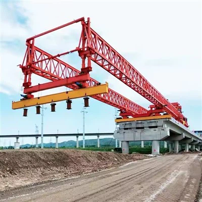
A bridge girder launching machine is a specialized piece of construction equipment used to erect prefabricated bridge girders or segments onto bridge piers. It is essential for bridge construction, particularly where ground access is limited, as it operates from above, launching itself and the bridge sections forward span by span.

Key Specifications
| Parameter | Specification |
|---|---|
| Rated Lifting Capacity | 100 tons-180tons |
| Adaptable Bridge Span | 30–50 m (customizable) |
| Working Duty | A5–A7 |
| Power Supply | 3-phase AC 380V, 50Hz |
| Lifting Speed | 0.8–1.5 m/min (frequency control) |
| Longitudinal Travel Speed | 0–6 m/min |
| Lateral Travel Speed | 0–3 m/min |
| Adaptable Longitudinal Slope | ≤ 2–5% |
| Minimum Curve Radius | R ≥ 150–350 m |
| Skew Bridge Angle | 0–15° |

Pictures & Components
I. Main Load-Bearing Structure
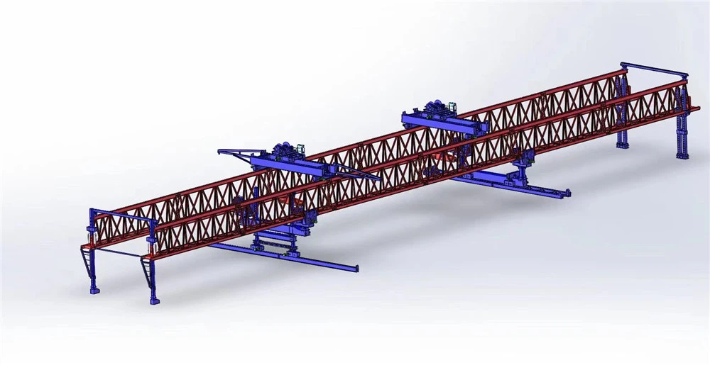
1. Main Girder / Guide Beam
The primary load-bearing skeleton of the entire machine, typically a steel box girder or truss structure.
Bears the weight of the precast girder being erected and the machine's own dead load.
Serves as the track foundation for the longitudinal travel of the lifting trolley.
2. Front Nose / Launching Nose
An auxiliary beam segment at the front of the main girder that can extend forward.
During span launching (moving to the next span), it reaches ahead to rest on the forward pier, providing support and guidance to prevent overturning.
II. Support and Travel System
3. Front Leg
Supports the machine on the forward pier, usually equipped with hydraulic telescoping capability.
Adapts to different pier heights and longitudinal slopes; serves as the main front support during launching and girder erection.
4. Middle Leg
Supports on the completed bridge deck or pier top, providing intermediate support.
On some models, it can be retracted or shifted to allow the lifting trolley and girder to pass through.
5. Rear Leg
Supports on the completed bridge deck, carrying rear loads and maintaining overall stability.
Often fitted with traveling wheels or a longitudinal moving mechanism to enable longitudinal movement of the whole machine.
6. Auxiliary Launching Leg
Assists in jacking and longitudinal launching during span-crossing operations, working with the front nose to advance the machine.
7. Traveling Wheel Boxes / Longitudinal Moving Mechanism
Mounted at the bottom of the legs, driving the machine to travel longitudinally along the bridge axis.
Some models also have transverse moving capability for curve sections or lateral alignment adjustment.
III. Lifting and Hoisting System
8. Lifting Trolley / Hoist Trolley
Travels longitudinally along the track on top of the main girder.
Directly performs lifting, longitudinal transport, and lowering of the girder into position.
Some models are equipped with dual trolleys for tandem lifting of long girders or multi-point synchronous hoisting.
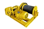
9. Hoisting Winch
Provides lifting power, raising and lowering the girder through wire rope and pulley systems.
Equipped with brakes and limit devices to ensure safe lifting and lowering.
10. Lifting Spreader / Lifting Beam
Connects the hoisting wire ropes to the girder being erected, distributing lifting force evenly.
Designed specifically for different girder types (box girders, T-beams, etc.) to prevent local damage to the girder.
IV. Power and Control System
11. Hydraulic System
Drives leg telescoping, longitudinal launching jacking, trolley movements, etc.
Includes hydraulic pump station, cylinders, valve groups, and piping.
12. Electrical Control System
The "brain" of the machine, coordinating the sequence of all mechanism movements.
Includes control console, frequency converters, sensors, and PLC control units.
13. Safety Monitoring System
Monitors parameters such as load, inclination angle, wind speed, and travel limits.
Triggers alarms or automatic shutdown when limits are exceeded, preventing overturning and overload accidents.
V. Auxiliary and Safety Devices
14. Anchoring and Wind-Resistant Devices
Anchor the machine to the bridge deck during non-working periods or in strong winds to prevent sliding and overturning.
15. Anti-Overturning Device
Provides additional anti-overturning moment during span launching and girder erection, ensuring safety under extreme conditions.
16. Walkways and Working Platforms
Provide safe passage and working areas for operators and maintenance personnel.
17. Generator Set / External Power Supply
Provides power source for the hydraulic and electrical systems; some models carry their own generator set.

Sketch

Advantages
🏗️ Minimal Environmental Impact and Site Interference
Fully Overhead Construction: Construction operations are conducted entirely from above, without the need to set up ground-based cranes or scaffolding below the bridge, making it particularly suitable for ecologically sensitive areas (such as river valleys) or difficult terrain.
No Disruption to Ground Traffic: When crossing existing roads, railways, or waterways, it does not interfere with traffic below or affect the normal operation of the infrastructure.
⚡ High Construction Efficiency and Predictability
Fast Span Erection Speed: Some projects can complete erection of one span in approximately 24 hours; in actual projects, construction progress exceeded contractor expectations, with completion four months ahead of schedule.
Intelligent Construction Enhances Efficiency: The newly developed self-rotating intelligent launching system, through real-time monitoring and dynamic correction, reduced the total construction period by approximately 30% and controlled axis deviation within 50 mm.
🎯 High Precision and Quality Assurance
Precise Positioning: Equipped with frequency conversion speed control and precise positioning technology, enabling smooth start-stop and millimeter-level alignment.
Favorable for Prefabrication Quality: Segments are prefabricated in factories, resulting in more stable quality compared to on-site casting, with more controllable curing conditions.
💰 Economic and Equipment Advantages
Economical for Specific Spans: When span lengths exceed the range achievable by cranes, launching machines are often a more cost-effective choice. For multi-span long bridges, span-by-span construction is considered one of the most economical and rapid methods.
Equipment Reusability: Equipment such as jacking mechanisms and sliding bearings can be reused in multiple projects, reducing capital investment.
🛡️ Safety
Reduced Aerial Operations: Since construction personnel do not need to perform extensive operations below the bridge, the risk of working at height and in hazardous areas is reduced.
High Safety Monitoring Level: Equipped with overload protection, limit switches, and other devices, and integrated with monitoring systems, ensuring structural stress and deformation remain within safe limits.


Application
| Application Scenario | Typical Bridge Type | Representative Case or Parameter |
|---|---|---|
| High-speed rail box girders | 20–40m precast box girders | 40m/970t full-span box girder; 900t class launching machine |
| Urban viaducts | Precast segmental box girders | 50m span/830t, span-by-span method |
| Steel girders/composite girders | Steel box girders, composite girders | Ethiopia railway, 46.4m typical span |
| Environmentally sensitive areas | Various | Oleron Viaduct, Hanging Lake Viaduct |
| Curved/small-radius bridges | Box girders, T-girders | Small-radius curve launching machine |

Production Procedure
1. Procurement and Pre-processing
Core components and key parts are mainly manufactured in-house, while standard parts and functional components are purchased externally. For non-standard parts with high production input but relatively simple processing, external processing is often adopted (the company provides drawings and commissions professional manufacturers). Prior to fabrication, raw materials such as steel plates and profiles must undergo pre-treatment, including deformation correction, shot blasting for rust removal, and primer coating, to ensure no defects such as rust, scars, or inclusions exist on the surface and inside.
2. Structural Component Fabrication
This is the core link determining the machine's load-bearing capacity. Taking the guide beam (an important load-bearing component) as an example, the process includes: welding side plates on both sides of H-beams to form square tubes, then clearing weld slag and polishing weld marks, and inspecting weld quality; subsequently, CNC machining centers are used to drill pin holes according to drawings, connecting plates are inserted and fixed with pins to form chord members; finally, in the assembly tooling, one upper chord and two lower chords are combined into a triangular truss structure, and node plates and web members are welded to form the guide beam. For 900-ton class high-speed railway launching machines, key structural components also need to undergo targeted technical requirement analysis and process optimization.
3. Pre-assembly and Surface Treatment
After fabrication of structural members, machined parts, externally processed parts, and purchased components is completed, pre-assembly is carried out according to mechanical-electrical-hydraulic design and technical process plans. The assembled structure then undergoes processes such as sand blasting and spray painting to complete anti-corrosion treatment.
4. Sub-assembly and Final Assembly
On the basis of pre-assembly, hydraulic sub-assembly and electrical sub-assembly are carried out separately, and finally the overall final assembly is completed. This step integrates the power system (hydraulic pump station, cylinders, pipelines) and control system (electrical cabinets, sensors, wiring) with the structural body to form a complete machine.
5. Inspection, Disassembly, and Transport
After the product is confirmed to be qualified through inspection, it is disassembled and transported to the customer's designated location according to transport requirements. Due to the large dimensions of launching machines (some models are 91 meters long), they typically must be transported in sections and reassembled on-site.


Workshop View
The company has installed an intelligent equipment management platform, and has installed 310 sets (sets) of handling and welding robots. After the completion of the plan, there will be more than 500 sets (sets), and the equipment networking rate will reach 95%. 32 welding lines have been put into use, 50 are planned to be installed, and the automation rate of the entire product line has reached 85%.


Hot Tags: bridge girder launching machine, China bridge girder launching machine manufacturers, suppliers, factory
You Might Also Like



Send Inquiry