


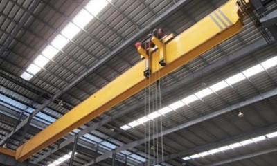
Single Beam 7T Bridge Crane
Basic Specifications
Lifting Capacity: 7 tons (7,000 kg)
Span: Customizable, commonly between 5–30 meters
Lifting Height: Customizable, depending on facility needs
Working Class: A3–A5 (light to medium duty)
Control Modes: Pendant control, wireless remote control, or cabin (optional)
Capacity: 1-20ton
- Capacity: 3.2-80ton
- Span length: 4-31.5m
- Lifting height:customized according to clients' site conditions
- Work duty: FEM Standard A5
- Raged voltage: 220V~690V, 50-60Hz, 3ph AC
- Protection class: IP54 IP55
- Crane control mode: Pendantcontrol / Remote control / Cabin control

Pictures & Components
1. Main Components:
1)Main Girder
Structure: I-beam or box-type welded beam made from high-strength steel.
Function: Supports the hoist and allows lateral movement across the span.
Design: Optimized for load-bearing while keeping deadweight low.
2)End Carriages
Equipped with traveling wheels and motors to allow the crane to move along the runway beams.
Typically uses geared motors with soft start features for smooth movement.
3)Electric Hoist
Usually an electric wire rope hoist or chain hoist depending on lift height and duty cycle.
Mounted under the main girder and moves horizontally along it.
Includes motor, drum, wire rope/chain, and hook block.
4)Crane Traveling Mechanism
Allows the entire crane to travel along the rails of the workshop or facility.
Controlled via motors with braking systems to prevent slippage or overtravel.
5)Electrical Control System
Includes control panel, motors, limit switches, overload protection, and interface for user operation.
Operated via push-button pendant, remote controller, or optional cabin.

2. Drive Mechanism:
Common drive types for single beam cranes:
Central drive (single motor driving both sides via a shaft – less common today)
Dual drive / Independent drive (one motor per end carriage – more modern and reliable)
For 7T cranes, the dual drive system is most common:
Each end carriage is powered by an independent motor-reducer unit.
Squirrel cage motors or tapered rotor motors are often used for high starting torque.
Motors are soft-start or frequency-controlled to prevent jerky movement and reduce mechanical wear.

3. Electrical System:
Power Supply
Voltage Options: Typically 380V/3Ph/50Hz (customizable for local standards: 220V, 415V, etc.)
Power Input Location: One end of the crane or near the control panel
Power Transmission:
Cable festoon system or sliding conductor bars (for crane travel)
C-track festoon system (for trolley and hoist power)

4. Safety Components:
1)Limit Switches
Lifting Limit Switch: Prevents the hoist hook from over-raising or over-lowering.
Travel Limit Switches: Installed at the end of the crane's runway and trolley track to prevent over-travel or collision.
Rotary or Lever-Type switches are commonly used.
2)Emergency Stop Button
Located on the pendant control or remote controller.
Immediately cuts all electrical power to the crane in case of an emergency.
3)Overload Protection Device
Integrated into the hoist system.
Prevents the crane from lifting a load heavier than the rated 7 tons.
May use:
Load cells
Torque-limiting clutch
Electronic overload sensor
4)Brake Systems
Electromagnetic Brakes are used on motors to automatically engage when power is off, preventing accidental motion.
Provides fail-safe stopping in power loss situations.
5)Main Power Disconnect Switch
Manually operated switch to shut off all electrical power before maintenance or during an emergency.

5. Supporting Structure:
Design Considerations
Load calculations must include:
Static and dynamic loads
Load impact factors
Wind or seismic forces (outdoor cranes)
Deflection limits must meet standards (usually L/600 or better).
All materials and welds should comply with relevant structural codes (ISO, FEM, GB, ANSI).
6. Optional Accessories:
1)Radio Remote Control
Wireless control for operator mobility and better visibility of the load.
Can replace or work alongside pendant control.
Usually comes with dual-speed or VFD-compatible options.
2)Variable Frequency Drive (VFD)
Controls lifting/traveling speeds smoothly.
Reduces load swing, extends motor life, and improves positioning accuracy.
3)Anti-Sway System
Electronic control that reduces pendulum motion of the load during travel.
Greatly improves safety and precision in load placement.
4)Load Display/Weighing System
Shows real-time lifted weight on an LED screen.
Alerts operators of overload conditions.
Integrated with overload limiter.
5)Overload Protection System
Prevents lifting loads above rated capacity.
Can be mechanical (spring-loaded limiter) or electronic (load cell-based).

11. Crane hook
Type of Hook
Single Hook (standard):
Most common type for 7T capacity.
Suspended from a hook block or rope drum hoist.
Swivels for easy load alignment.
Optional:
Double hook block (for better load distribution or dual lifting points-less common at 7T level).
C-hook, slab tong, or magnetic hook-custom lifting attachments for specific materials.

12. Sketch

Main Technical Data


Advantages
1. Compact Design
Space Efficiency: The single girder design allows for a more compact crane structure, making it suitable for environments where space is limited.
Lightweight Construction: The crane is often lighter compared to double girder cranes, which can reduce installation time and costs.
2. Cost-Effective
Lower Initial Cost: Single beam cranes are generally less expensive than double girder cranes due to simpler construction and fewer materials.
Energy Savings: The efficient design and use of modern motors (e.g., VFD) contribute to energy savings.
3. Ease of Installation
Quick Setup: Due to the simplified structure, the crane can be installed faster, reducing downtime and getting your operation up and running sooner.
Reduced Foundation Requirements: Lighter than double girder cranes, meaning less complex foundations are required.
4. High Lifting Capacity (7 Tons)
Heavy Lifting: With a 7-ton capacity, the crane is perfect for lifting heavier loads compared to other light-duty cranes, making it suitable for industries such as manufacturing, construction, and warehouses.
5. Smooth and Precise Operation
Accurate Load Handling: Equipped with precision control systems, single beam cranes ensure smooth and accurate handling of loads.
Reduced Load Swing: With options like anti-sway systems and VFD (Variable Frequency Drives), load movement can be controlled better, minimizing swing and enhancing precision.
6. Safety Features
Advanced Safety Systems: Includes overload protection, limit switches, emergency stop buttons, and more, ensuring safer operations.
Enhanced Stability: The single beam design is often more stable in smaller spaces with less chance of tipping or instability.
Application
1. Manufacturing and Assembly Lines
Purpose: Lifting and transporting heavy components during production and assembly processes.
Examples:
Automotive: Moving heavy engine parts, car frames, or assembly components.
Electronics: Lifting and positioning heavy machinery, metal parts, or assembly lines.
Benefit: Increased productivity and safety in assembly operations.
2. Warehousing and Distribution
Purpose: Efficient material handling in storage areas, facilitating easy movement of goods from one place to another.
Examples:
Palletized goods: Lifting and stacking heavy pallets or packages.
Storage of large items: Moving large equipment, machinery, or bulk materials.
Benefit: Saves time and labor, reducing manual lifting and improving storage organization.
3. Steel Industry
Purpose: Handling raw materials, such as metal sheets, rods, pipes, and steel coils.
Examples:
Lifting steel coils, plates, or bars in warehouses or production lines.
Hot metal handling (optional for high-temperature environments).
Benefit: Ensures smooth and safe handling of heavy, sometimes hazardous, materials.
4. Construction
Purpose: Lifting and transporting heavy construction materials, tools, or equipment.
Examples:
Lifting concrete beams, steel girders, or other structural components.
Moving materials around construction sites.
Benefit: Increases site productivity and reduces the need for manual labor in lifting.
5. Repair and Maintenance
Purpose: Lifting and supporting large machinery or equipment for repair or maintenance.
Examples:
Lifting motors, generators, or other heavy equipment during maintenance.
Transporting replacement parts or tools.
Benefit: Reduces downtime and makes maintenance processes more efficient and safer.
6. Shipbuilding and Marine Industry
Purpose: Lifting and transporting ship components such as hull sections, heavy equipment, and materials used in ship construction and maintenance.
Examples:
Moving heavy ship sections, propellers, or engines during construction.
Lifting heavy machinery for installation or repair on ships.
Benefit: Provides efficient and safe lifting of bulky components in shipyards.
7. Energy and Power Plants
Purpose: Handling large components during construction or maintenance of energy plants, especially for nuclear, solar, wind, or thermal power plants.
Examples:
Lifting and moving transformers, generators, or motors in power plants.
Handling large turbine parts in renewable energy plants.
Types Of Cranes For Different Working Conditions

Crane Production Procedure
1.Design and Engineering
Pre-production Design:
Engineers assess customer requirements (load capacity, dimensions, environment).
Design includes detailed drawings, structural calculations, material specifications, and safety features.
Computer-aided design (CAD) software and simulation tools are used to finalize the crane design.
Approval Process:
Designs are reviewed and approved by both the engineering team and the customer (if necessary).
Compliance with relevant standards (ISO, FEM, CE, etc.) is ensured.
2. Material Procurement
Selection of Raw Materials:
High-strength steel plates (for the main girder and structural components).
Forged steel or alloy steel for key components such as hooks, wheels, and axles.
Electrical components like motors, switches, control panels, and wiring are sourced.
Optional accessories (e.g., VFDs, remote control systems) are ordered as per specifications.
Material Testing:
All materials undergo quality inspection, including tensile tests, hardness checks, and welding inspections.
Certifications and material traceability are maintained.
3. Fabrication of Main Components
Main Girder:
The single girder is fabricated from welded steel plates.
The girder is cut, welded, and machined to meet precise specifications.
The beam is tested for structural integrity using non-destructive testing (NDT), such as ultrasonic or X-ray testing.
End Carriages:
The end carriages are welded and assembled. These are the structures that allow the crane to travel along the runway rails.
They include motor mounts, wheels, and gearbox mounting points.
Hoist and Trolley:
The hoist unit (lifting mechanism) is assembled with its motor, brake system, and hook.
The trolley system is fabricated, which carries the hoist along the girder beam.
4. Mechanical Assembly
Main Girder and End Carriages:
The main girder is lifted into place and connected to the end carriages to form the basic structure of the crane.
Wheels and axles are installed on the end carriages to allow movement along the runway.
Travel Mechanism:
The crane traveling system is installed, which includes the motor, gearbox, and control systems that drive the crane along the rails.
Trolley and Hoist Installation:
The trolley system is mounted onto the girder and connected to the hoist mechanism.
Hooks, wire ropes, and hoist drums are installed.
5. Electrical and Control Systems
Wiring and Connection:
All electrical components, including the motor, control panel, limit switches, safety alarms, and lights, are wired and connected to the system.
Control System Installation:
The control system is installed, either as a pendant control or radio remote control (if specified).
Variable Frequency Drives (VFDs) are installed for smooth, controlled movement (optional).
Testing:
Electrical systems undergo thorough testing to ensure proper function, safety, and comply with standards.
Electrical insulation tests and control signal checks are performed.
6. Testing and Quality Control
Initial Testing:
The crane is powered up and static tests are performed on all components to check for basic functionality.
Load testing is done by gradually lifting a test weight (typically 125% of the rated load capacity) to check the crane's performance under stress.
Dynamic Testing:
The crane is run through all motions: lifting, traveling along the runway, and trolley movement.
Safety systems like overload protection, limit switches, and braking systems are thoroughly tested.
Quality Assurance:
After initial tests, a final inspection is conducted to ensure all components meet specifications.
The crane is inspected for defects in welding, painting, assembly, and alignment.
Documentation and Certification:
A performance report and certification of compliance are generated.
The crane's serial number is recorded for future maintenance tracking.
7. Painting and Surface Treatment
Surface Preparation:
All metal surfaces are cleaned and treated to remove rust and contaminants.
Anti-corrosion coatings are applied to ensure longevity.
Painting:
The crane is painted with industrial-grade paints, typically with high-visibility colors for safety (e.g., yellow or orange).
Weather-resistant paint is used for outdoor cranes.
8. Final Assembly and Testing
Assembly:
All components (motors, controls, wheels, hooks) are assembled and securely fastened.
The crane is assembled in its final configuration.
Final Load Test:
The crane is tested under full load capacity (7 tons) to ensure smooth operation and proper load handling.
Any adjustments needed are made during this phase.
9. Packaging and Delivery
Shipping Preparation:
The crane is disassembled into transportable components (if necessary) and securely packaged for shipping.
Assembly instructions, manuals, and other necessary documentation are provided.
Delivery:
The crane is delivered to the client's location, either fully assembled or for final on-site assembly, depending on the order.
10. On-Site Installation and Commissioning
Installation:
The crane is installed at the customer's site, including connecting the runway rails, hoist, and control systems.
Final Testing and Training:
Commissioning is done on-site to ensure everything works as expected.
Operators are trained on safe usage, basic troubleshooting, and maintenance.

Workshop View
The company has installed an intelligent equipment management platform, and has installed 310 sets (sets) of handling and welding robots. After the completion of the plan, there will be more than 500 sets (sets), and the equipment networking rate will reach 95%. 32 welding lines have been put into use, 50 are planned to be installed, and the automation rate of the entire product line has reached.


Hot Tags: single beam 7t bridge crane, China single beam 7t bridge crane manufacturers, suppliers, factory, Single Girder Overhead Travelling Crane, Single Girder Overhead Crane
You Might Also Like


Send Inquiry