






LX 2t Electric Single Girder Underslung Crane (Suspension Crane) manufacturers
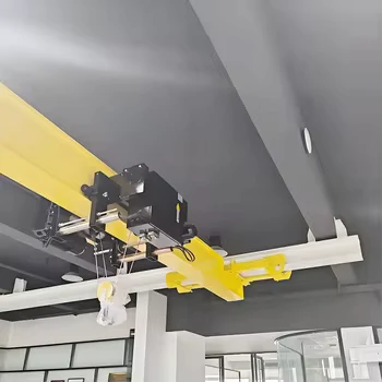
LX 2t Electric Single Girder Underslung Crane (Suspension Crane) suppliers
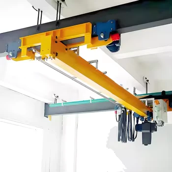
LX 2t Electric Single Girder Underslung Crane (Suspension Crane) factory
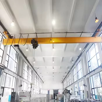
LX 2t Electric Single Girder Underslung Crane (Suspension Crane) best
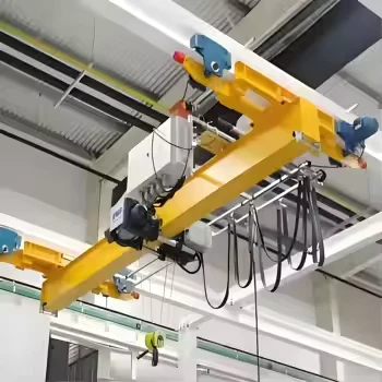
LX 2t Electric Single Girder Underslung Crane (Suspension Crane) high quality
LX 2t Electric Single Girder Underslung Crane (Suspension Crane)
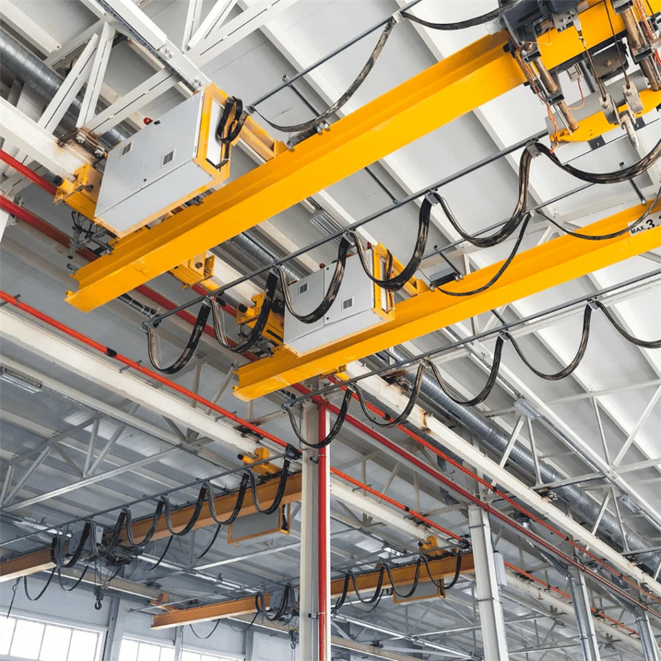
An LX 2t Electric Single Girder Underslung Crane (also known as an Underhung or Suspension Overhead Crane) is a space-saving, light-duty material handling system engineered for facilities without floor support columns or corbels. Instead of riding atop traditional runway beams, the LX crane's end carriages are suspended directly from the bottom flange of roof-mounted I-beams or H-beams.
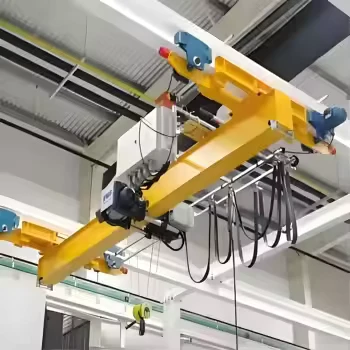
Manufactured in strict accordance with JB/T 2603-2008 standards, the LX 2t Underslung Crane operates in tandem with a CD1 (single-speed) or MD1 (dual-speed) electric wire rope hoist. Because the entire bridge structure hangs beneath the overhead runway tracks, it requires only ≥100 mm of vertical clearance between the highest point of the crane and the building roof ceiling, maximizing floor space utilization in compact workshops, water treatment plants, pump rooms, and automated warehouses.
Featuring a lightweight deadweight (only 1,100 kg to 1,130 kg for a 2-ton system), flexible side cantilevers that extend the hook coverage beyond the runway rails, and smooth three-in-one geared drive motors, the LX 2t Suspension Crane is the most economical overhead lifting solution for light industrial and municipal maintenance facilities.
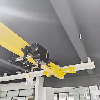
Capacity: 2 ton (Full LX series range: 0.5t, 1t, 2t, 3t, 5t, 10t)
Span length: 3m – 16m (Drawing benchmarks: 3m, 4.2m)
Lifting height: 3.6m – 18m (Drawing benchmarks: 3.6m, 4m)
Work duty: ISO M3 / M4 (Class A3 / A4 Light-to-Medium Duty)
Rated voltage: 220V~480V, 50–60Hz, 3-Phase AC (Standard: 380V 50Hz)
Headroom clearance requirement: Building roof height $\ge 100\text{ mm}$ above crane highest point
Crane control mode: Ground Pendant control / Wireless Radio remote control
Pictures & Components (De-duplicated & Professionally Rewritten)
1. Whole set crane
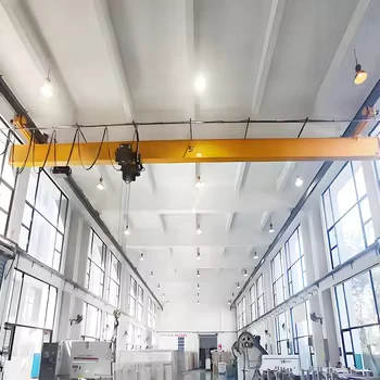
The LX 2t electric single girder underslung crane comprises a U-channel and I-beam composite main bridge girder, two inverted suspension end trucks, a 2-ton electric wire rope hoist, and a C-track festoon power supply system. By hanging directly from the facility's existing roof trusses or ceiling I-beams, it completely eliminates the expense of erecting floor-standing steel columns, keeping the shop floor 100% unobstructed for forklifts and production machinery.
2. Main girder
Fabricated from cold-rolled U-shaped steel channels welded to a standard hot-rolled I-beam (or full welded box girder for wider spans), the main girder provides a rigid lower flange track for the electric hoist trolley. Unlike top-running cranes, the LX main girder extends slightly past the runway centerlines with short side overhangs ($300\text{ mm}$ side cantilevers), allowing the hoist hook to reach closer to the side walls of the building.
3. Lifting System
Hoisting is handled by a modular 2-ton CD1 (8 m/min single speed) or MD1 (8 / 0.8 m/min dual speed) electric wire rope hoist suspended from the bottom flange of the main girder. Powered by a conical-rotor brake motor (ZD1/ZDS series), the hoist integrates a precision planetary reducer, a grooved wire rope drum with a rope guide, and a mechanical-electrical fire-stop limit switch to prevent over-hoisting.
4. Underslung End Carriages
Engineered specifically for underhung operation, the inverted end carriages straddle the bottom flange of the overhead runway I-beam (such as I20a–I32b).
Built from reinforced rectangular steel tubes and heavy-duty suspension side plates, they incorporate safety anti-drop lugs (safety catch brackets) that prevent the crane from derailing or falling even in the event of a wheel or axle failure.
Rubber or polyurethane bumpers are mounted at both ends of the end trucks to absorb kinetic impact at runway stops.
5. Crane traveling mechanism
Longitudinal travel along the ceiling tracks is powered by twin conical-rotor brake motors (ZDY12-4, $2 \times 0.4\text{ kW}$) or compact three-in-one soft-start gearmotors. Delivering a smooth travel speed of 20 m/min (or 30 m/min), the synchronized dual drive prevents bridge skewing across short 3m to 4.2m spans.
6. Trolley traversing mechanism
The electric hoist is carried by a four-wheel motorized monorail trolley driven by a $0.4\text{ kW}$ brake motor at 20 m/min.
Adjustable spacer washers on the trolley suspension shaft allow the wheel gauge to be fine-tuned during installation to match the exact bottom flange width of the main girder.
Side guide rollers minimize flange friction and ensure smooth cross-travel positioning.
7. Crane wheel
The suspension end-carriage wheels feature a single-flange or flangeless bevel-tread profile specifically machined to ride smoothly along the sloped or flat lower flange of standard runway I-beams.
Forged from 45# high-carbon steel or 42CrMo alloy steel with induction-hardened treads (HB 300–350) to resist wear and protect the overhead roof tracks.
Maintenance-free sealed deep-groove ball bearings provide quiet, low-resistance rolling.
8. Crane hook
Fitted with a drop-forged DG20 carbon steel single hook rated for a 2-ton safe working load with a $5:1$ safety factor. The hook swivels 360 degrees on a sealed thrust bearing inside a fully shrouded sheave block and includes a spring-loaded safety latch to prevent rigging slings from slipping off.
9. Motor
Equipped with conical-rotor self-braking motors (ZD/ZDY series) featuring Class B/F insulation and IP44/IP54 enclosure protection. Whenever power is disconnected, the axial spring immediately forces the conical brake wheel against the rear end cover, delivering reliable, slip-free braking without requiring external hydraulic thrusters or complex brake rectifiers.
10. Sound and light alarm system & limit switch
An audible-visual strobe alarm is mounted on the bridge electrical box to warn floor workers when the crane is in motion. Dual-direction travel limit switches automatically cut off power before the end carriages reach the ends of the ceiling tracks, while the hoist's upper/lower limit switch protects the wire rope drum.
11. Safety Devices
Structural anti-drop safety lugs: Welded onto both end carriages and the hoist trolley to lock onto the I-beam flange and prevent accidental falling.
Overload limiter: Electronic load sensor cuts off upward hoisting power and sounds a buzzer if the load exceeds 105% of 2 tons.
Fire-stop upper limit switch: Mechanically disconnects the main hoist motor circuit if the hook block rises past the normal rotary limit.
Emergency stop button & electrical protection: Isolates main power instantly; includes short-circuit, phase-loss, and under-voltage relays.
12. Control Mode
Ergonomic Pendant Control: Suspended low-voltage ($36\text{V} / 48\text{V}$) push-button station sliding along a C-track festoon cable, allowing the operator to walk alongside the load.
Wireless Radio Remote Control: Compact industrial push-button transmitter with a 100m control range, ideal for operating the crane across equipment-congested pump rooms or pits.
13. Sketch
(Dimensional Layout Reference based on Drawings LX1t-3m, LX2t-3m & LX2t-4.2m)
Span ($S$): $3,000\text{ mm}$ / $4,200\text{ mm}$
Side Overhang Cantilever: $300\text{ mm}$ on each side
End Carriage Wheelbase: $2,300\text{ mm}$
Lifting Height ($H$): $3.6\text{ m}$ ($1\text{t}$) / $4.0\text{ m}$ ($2\text{t}$)
Minimum Roof Headroom Clearance: $\ge 100\text{ mm}$ above the highest point of the crane
Total Crane Deadweight: $1,028\text{ kg}$ (LX1t-3m) / $1,100\text{ kg}$ (LX2t-3m) / $1,130\text{ kg}$ (LX2t-4.2m)

Main Technical Data (LX 1t & 2t Engineering Drawing Benchmarks)
| Parameter Item | Unit | Model: LX 1t-3m | Model: LX 2t-3m | Model: LX 2t-4.2m | Custom LX Series Range |
| Rated Lifting Capacity ($Q$) | t |
1 t |
2 t |
2 t |
0.5 t – 10 t |
| Span Length ($S$) | m (mm) |
3 m ($3,000\text{ mm}$) |
3 m ($3,000\text{ mm}$) |
4.2 m ($4,200\text{ mm}$) |
3 m – 16 m |
| Valid Lifting Height ($H$) | m |
3.6 m |
4.0 m |
4.0 m |
3 m – 18 m |
| Total Crane Deadweight | kg |
1,028 kg |
1,100 kg |
1,130 kg |
950 – 4,800 kg |
| Side Cantilever Length | mm |
300 mm |
300 mm |
300 mm |
250 – 1,000 mm |
| End Carriage Wheelbase | mm |
2,300 mm |
2,300 mm |
2,300 mm |
2,000 – 2,500 mm |
| Min. Roof Clearance | mm |
$\ge 100\text{ mm}$ |
$\ge 100\text{ mm}$ |
$\ge 100\text{ mm}$ |
$\ge 100\text{ mm}$ |
| Hoisting Speed | m/min | 8 (or 8/0.8) | 8 (or 8/0.8) | 8 (or 8/0.8) | 7 – 8 (Single/Dual) |
| Trolley Traversing Speed | m/min | 20 | 20 | 20 | 20 / 30 (or VFD) |
| Crane Traveling Speed | m/min | 20 | 20 | 20 | 20 / 30 (or VFD) |
| Matching Electric Hoist | Model | CD1 / MD1 1t-6m | CD1 / MD1 2t-6m | CD1 / MD1 2t-6m | CD1 / MD1 / European |
| Hoisting Motor Power | kW | 1.5 kW | 3.0 kW | 3.0 kW | 0.8 – 13.0 kW |
| Crane Travel Motor Power | kW | 2 × 0.2 kW | 2 × 0.4 kW | 2 × 0.4 kW | 2 × 0.2 – 2 × 0.8 kW |
| Recommended Runway Track | I-Beam | I16 – I22a | I20a – I25b | I20a – I25b | I20a – I40b |
| Manufacturing Standard | Code |
JB/T 2603-2008 |
JB/T 2603-2008 |
JB/T 2603-2008 |
JB/T 2603-2008 |
Advantages
Zero Floor Column Footprint: Hangs directly from roof structures or ceiling beams, saving 100% of floor column costs and maximizing usable workshop floor area.
Ultra-Tight Roof Clearance: Needs only $\ge 100\text{ mm}$ of clearance above the crane's highest point, fitting into low-ceiling basements, pump rooms, and utility tunnels where top-running cranes cannot be installed.
Extended Side Coverage: The $300\text{ mm}$ side cantilevers allow the hoist trolley to travel beyond the runway rail span, eliminating dead zones along workshop walls.
Featherweight Structure: Weighing just $1,028\text{ kg}$ to $1,130\text{ kg}$, the crane imposes minimal static and dynamic loads on existing building roof trusses.
Fast Bolt-Together Installation: Delivered as a pre-wired modular kit; the main girder and suspension end trucks bolt together in hours without field welding.
Economical LCL/FCL Shipping: Compact 3m to 4.2m bridge lengths can be shipped via standard 20GP containers or even Less-than-Container-Load (LCL) wooden crates, drastically lowering freight expenses for small-order buyers.
Application
Municipal waterworks, sewage treatment plants, and subterranean pump stations.
Factory equipment repair rooms, tool & die maintenance bays, and compressor halls.
Light assembly lines for electronics, textiles, food processing, and packaging.
Multi-story industrial buildings and mezzanine floors where floor columns cannot be added.
Automated storage and retrieval warehouses (AS/RS) and spare parts depots. 6.HVAC chiller rooms and power plant auxiliary equipment rooms.
Crane Production Procedure
Design and engineering: Structural load and roof suspension verification executed in strict compliance with JB/T 2603-2008.
Material procurement: Certified Q235B/Q355B rolled I-beams, steel channels, and genuine CD1/MD1 wire rope hoists inspected upon arrival.
CNC Cutting and shaping: Precision plasma cutting of web stiffeners and suspension end-truck side plates.
Automated Welding: Submerged-arc and $\text{CO}_2$ gas-shielded welding of the composite U-channel/I-beam girder with ultrasonic weld inspection.
Shot blasting and coating: Full steel structure shot-blasted to ISO Sa2.5 grade and finished with two coats of epoxy primer and two coats of industrial safety yellow topcoat.
End carriage machining: Precision boring of wheel axles and welding of anti-drop safety catch lugs onto the inverted end carriages.
Shop trial assembly: Pre-assembling the main girder and suspension end trucks on a test jig to verify the $2,300\text{ mm}$ wheelbase and $3,000\text{ mm} / 4,200\text{ mm}$ span tolerances.
Electrical pre-wiring: Installing the C-track festoon system, travel limit switches, and control box.
Final inspection and packing: No-load hoist and travel testing prior to export wrapping and crating.

Workshop View
The company has installed an intelligent equipment management platform, and has installed 310 sets of handling and welding robots. After the completion of the plan, there will be more than 500 sets, and the equipment networking rate will reach 95%. 32 welding lines have been put into use, 50 are planned to be installed, and the automation rate of the entire product line has reached 85%.
Hot Tags: lx 2t electric single girder underslung crane (suspension crane), China lx 2t electric single girder underslung crane (suspension crane) manufacturers, suppliers, factory, Single Girder Overhead Crane, Single Girder Overhead Travelling Crane
You Might Also Like




Send Inquiry