


Electric Single Overhead Crane
Products Description
Advantages
Cost-Effective: Significantly less expensive to purchase and install compared to a double girder crane due to simpler design, lighter weight, and lower structural requirements.
Lighter Weight: Puts less stress on the building's support structure, making it ideal for existing facilities.
Space Efficient: Requires less headroom than a double girder crane, maximizing available vertical space.
Simplicity & Reliability: Fewer components mean easier maintenance and generally higher reliability for standard duties.
Ideal for Light/Medium Duty: Perfect for applications with lower capacities (typically up to 20 tons, though some can go higher) and less frequent use.
Disadvantages / Limitations
Lower Capacity: Not suitable for very heavy loads (e.g., > 20-25 tons) where a double girder design is required.
Shorter Spans: Generally not recommended for very long spans (e.g., > 100 ft / 30 m) as the single girder can sag (deflect) under load. Double girders provide superior rigidity for long spans.
Lower Hook Height: The hoist is mounted under the girder, which reduces the available hook height compared to a double girder crane where the hoist is mounted between the girders.
Duty Cycle: Less suited for extremely heavy-duty, high-frequency, or continuous (CASE D & E) applications that would cause excessive wear on the single girder.
Single Girder vs. Double Girder Crane
| Feature | Single Girder Crane | Double Girder Crane |
|---|---|---|
| Cost | Lower initial and installation cost | Higher cost |
| Headroom | Higher Hook Height: Hoist is under the girder, using more vertical space. | Higher Hook Height: Hoist sits between girders, maximizing lift height. |
| Capacity | Light to Medium Duty (Typically up to 20 tons) | Medium to Heavy Duty (Can exceed 100+ tons) |
| Span Length | Short to Medium Spans | Medium to Very Long Spans |
| Duty Cycle | Light to Moderate (Classes A-C) | Moderate to Severe (Classes C-E) |
| Maintenance | Generally simpler | Can be more complex |
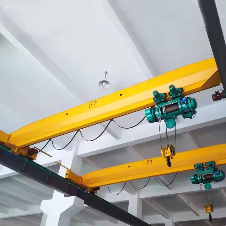
Lifting Capacity 1 – 20 tons (custom up to 50+ tons)
Span 5 – 30 meters
Lifting Height 3 – 30 meters
Lifting Speed 1 – 20 m/min (adjustable)
Trolley Speed 5 – 30 m/min
Crane Travel Speed 10 – 60 m/min
Power Supply 380V/415V, 50Hz (3-phase)
Duty Class FEM A3-A5 (Medium to Heavy Duty)

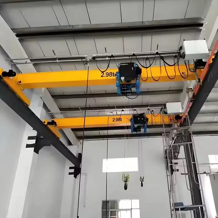
Pictures & Components
1. Structural Components
These parts form the main framework of the crane and support all other components and the load.
Bridge Girder: The primary horizontal beam that spans the work area. It is typically a rolled steel I-beam or a fabricated box-type beam. The trolley and hoist run along the bottom flange of this girder.
End Trucks: These are the sturdy housings attached to each end of the bridge girder. They contain the wheels, axles, and bearings that allow the entire crane to travel.

Runway System: This is the fixed path on which the crane moves. It is not part of the crane itself but is essential for its operation. It consists of:
Runway Beams: Heavy-duty steel I-beams securely attached to the building's support columns or structure.
Runway Rails: The steel rails (often a specific crane rail, but sometimes the top flange of the beam itself) on which the crane's wheels run. They must be precisely aligned.
Bumpers (Buffers): Energy-absorbing devices (often made of rubber or polyurethane) mounted on the end trucks and at the ends of the runway to absorb impact and safely halt crane movement at its limits.
 |
 |
2. Mechanical / Movement Components
These parts provide the crane's mobility.
Travel Wheels: The wheels housed within the end trucks that support the crane and allow it to move along the runway rails. Non-powered wheels are called idler wheels.
Drive Units: The motorized assemblies that power the movement. A single girder crane typically has two main drives:
Bridge Drive: The motor, brake, and gearbox assembly that powers the travel wheels in the end trucks to move the entire crane along the runway (long travel).
Trolley Drive: The motor and gearbox that moves the trolley (and hoist) back and forth along the length of the bridge girder (cross travel).
 |
 |
Gearboxes: Reduce the high-speed, low-torque output of the electric motors to the low-speed, high-torque power needed to move heavy loads.
Brakes: Fail-safe brakes are critical for safety. They are typically spring-set, electrically released and engage automatically in the event of a power failure to hold the load.

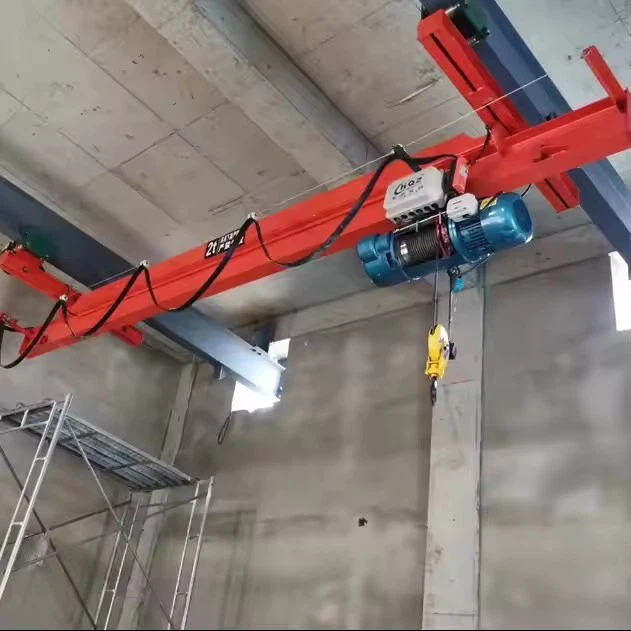
3. Lifting Components (The Hoist Unit)
This is the component that actually handles the load. On a single girder crane, the hoist is typically an integrated unit that runs on the bottom flange of the bridge girder.
Hoist Motor: The electric motor that provides power to lift and lower the load.
Lifting Medium:
Wire Rope Hoist: Uses a wire rope wound onto a drum. More common for heavier capacities and higher speeds.
Chain Hoist: Uses a welded link chain or load chain. Often more compact and cost-effective for lower capacities.

Drum or Sprocket:
For wire rope hoists: A grooved drum that spools the wire rope.
For chain hoists: A sprocket that meshes with the links of the chain.
Hook Block: The assembly that connects to the load. It includes a pulley/sheave and the hook itself. The hook can swivel to prevent twisting of the load.
Load Limiter / Overload Protection: A critical safety sensor that prevents the crane from lifting a load beyond its rated capacity.
Upper Limit Switch: An automatic switch that cuts power to the hoist motor to prevent the hook block from being raised too high and damaging the hoist or itself.

.
4. Electrical & Control Components
These parts provide power and command the crane's functions.
Power Delivery System:
Festoon System: The most common method. A series of cables (for power and control) are carried in a flexible tray that extends and retracts with the crane's movement.
Conductor Bar System (Enclosed Track): A rigid, insulated bar system mounted along the runway. Collector shoes on the crane slide along this bar to draw power. Preferred for longer distances, higher duty cycles, or harsh environments.

Control Device:
Pendant Control Station: A weather-proof box suspended from the crane with push buttons for Up/Down, East/West (Trolley), North/South (Bridge). The operator walks alongside the crane to control it.
Radio Remote Control: A wireless transmitter that allows the operator to control the crane from a distance, offering a better view of the load and increased safety by keeping the operator out of the load path.
Control Panel (Cabinet): Houses the electrical components like contactors, variable frequency drives (VFDs), overload protectors, and programmable logic controllers (PLCs) that manage power and logic for the crane's movements.
Variable Frequency Drives (VFDs): Optional but highly recommended. They provide smooth, controlled acceleration and deceleration, reducing load swing, mechanical stress, and improving positioning accuracy.

Sketch

Main technical

Advantages
Electric single girder overhead cranes are a popular choice for a wide range of industries due to their compelling combination of economic and practical benefits.
1. Cost-Effectiveness (Lower Initial Investment)
Simpler Design: With only one main girder, the structure is less complex to design and fabricate than a double girder crane.
Reduced Material Costs: They use less steel, making the crane itself less expensive to manufacture.
Lower Installation Costs: Being lighter, they are often easier and cheaper to install.
Reduced Supporting Structure Cost: The lighter weight places a smaller load on the building's support columns and runway structure, which can lead to significant savings in new construction or when retrofitting an existing building.
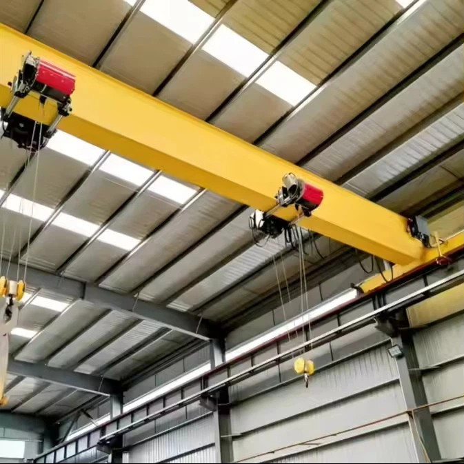
2. Optimal Use of Headroom
Compact Design: The hoist is mounted under the single girder, making the entire crane assembly very compact.
Maximized Lift Height: This low-profile design provides the maximum possible hook height for a given building ceiling height. This is a critical advantage in facilities with limited vertical space.
3. Lightweight and Efficient
The reduced weight not only saves on supporting structure but also means the crane's drive motors can be smaller and more energy-efficient to move the bridge along the runway.
4. Ease of Maintenance and Reliability
Simpler Construction: Fewer components (one girder, a simpler trolley/hoist system) mean there are fewer parts that can fail.
Accessibility: Key components like the hoist and trolley are easily accessible for inspection and maintenance, reducing downtime.
5. Versatility and Adaptability
They can be configured in various ways to suit specific needs, including:
Top-Running: The crane runs on rails mounted on top of the runway beams. This is the most common configuration, offering the highest lifting capacity.
Under-Running (Underhung): The crane wheels run on the bottom flange of the runway beams, which are typically supported by the roof structure. This allows for a system where multiple cranes can operate on the same runway system and even be transferred between bays.
6. Suitable for Light to Moderate Duty Cycles
They are perfectly designed for applications that require frequent but not extremely intense use (standard duty cycles classified as Class A through C).
Application:
These cranes are the workhorses of industry, ideal for any task that involves moving materials within a defined rectangular area. They are most commonly found in applications where capacity requirements are under 20 tons and spans are of moderate length.
1. Manufacturing and Assembly Plants
Moving Raw Materials: Transporting steel, aluminum, and other materials from storage to machining centers.
Workstation Feeding: Supplying parts and sub-assemblies to different points on a production line.
Handling Machinery: Lifting and positioning heavy machinery, molds, and equipment for setup or maintenance.
Loading/Unloading: Moving finished products from the assembly line onto trailers or into storage.
2. Warehousing and Distribution Centers
Loading Docks: Unloading trucks and placing goods onto storage racks.
Order Picking: Handling large, heavy, or palletized items that are beyond manual capability.
Storage Management: Moving goods to and from high-bay storage areas.
3. Workshop and Maintenance Bays
Automotive Garages: Removing and installing engines, transmissions, and bus/truck body panels.
Machinery Repair Shops: Handling large motors, pumps, and industrial equipment for repair.
Utility Facilities: Lifting transformers, switchgear, and other heavy electrical components.
4. Specific Industry Applications
Paper and Printing Industries: Handling heavy rolls of paper safely and precisely.
Metal Fabrication Shops: Moving sheet metal, steel coils, and fabricated parts.
Construction Material Suppliers: Handling bags of cement, lumber packs, and other building supplies.
Aerospace: Moving components like wings and fuselage sections in smaller manufacturing and maintenance hangars.
Crane production procedure
1. Design & Engineering
Requirement Analysis: Confirm load capacity, span, lift height, automation level, control mode, and safety features based on customer needs.
Structural Design: Design the single girder main beam, end carriages, trolley, and hoist assembly using CAD software.
Electrical & Control Design: Develop control system schematics including PLC programming, motor selection, VFDs, sensors, alarms, and safety interlocks.
Simulation & Validation: Use FEA (Finite Element Analysis) for structural integrity and dynamic simulation for motion control.
2. Material Procurement
Source high-quality steel (Q345B or equivalent) for main beam and components.
Acquire motors, hoists, VFDs, PLCs, limit switches, and alarm systems from trusted suppliers.
Ensure all components meet relevant certifications and standards (ISO, CE, GB).
3. Main Beam Fabrication
Cutting: Steel plates cut to size using CNC flame/plasma cutting machines.
Forming: Roll or shape plates into the I-beam or box girder profile.
Welding: Perform welding of flanges, web, and stiffeners following welding procedure specifications (WPS).
Heat Treatment: Stress relief if necessary to reduce welding deformation.
Machining: Drill holes for end carriage and trolley mounting; machine crane rails if integrated.
Inspection: Check weld quality (X-ray or ultrasonic), dimensions, and surface finish.
4. End Carriage & Trolley Assembly
Frame Fabrication: Cut and weld end carriage frames and trolley frames.
Wheel Assembly: Mount wheels and fit bearings; assemble drive motor and gearbox.
Installation: Attach wheels to frames and mount brakes and limit switches.
Testing: Static and dynamic tests on wheels and brakes for smooth rotation and load bearing.
5. Hoist Assembly
Assemble wire rope or chain hoist on the trolley.
Install hook block, safety latch, load limiter, and load sensors.
Connect hoist motor, gearbox, brake, and encoders.
Conduct functional tests on hoisting speed, lifting capacity, and braking.
6. Electrical Wiring & Control System
Install motor cables, control cables, and communication lines.
Mount PLC, VFDs, contactors, and safety relays in the control cabinet.
Wire limit switches, alarms, emergency stop, and sensors.
Program PLC with automated control logic, safety interlocks, and diagnostics.
7. Surface Treatment
Cleaning: Remove rust, oil, and debris from all steel parts.
Primer Coating: Apply anti-corrosion primer.
Final Paint: Spray high-durability industrial paint to protect against wear and corrosion.
Curing: Allow proper drying time to ensure finish quality.
8. Pre-Installation Testing
No-Load Tests: Run crane, trolley, and hoist without load to verify movement, speed, and control.
Load Test: Perform rated load test per standards to ensure lifting capacity and structural integrity.
Safety Device Check: Verify operation of overload limiter, limit switches, emergency stop, and alarms.
Automation Validation: Test automated sequences, positioning accuracy, and sensor feedback.
9. Packing & Shipping
Disassemble parts if necessary for transport.
Protect components with rust-proofing, padding, and secure packing.
Prepare documentation including user manuals, maintenance guides, and test certificates.
10. Installation & Commissioning (On-Site)
Reassemble crane components at customer site.
Align crane rails and secure runway structure.
Connect power and control wiring.
Calibrate sensors and test automated control functions.
Train operators and maintenance personnel.
Hand over documentation and certification.

Workshop view:
The company has installed an intelligent equipment management platform, and has installed 310 sets (sets) of handling and welding robots. After the completion of the plan, there will be more than 500 sets (sets), and the equipment networking rate will reach 95%. 32 welding lines have been put into use, 50 are planned to be installed, and the automation rate of the entire product line has reached 85%.


Hot Tags: electric single overhead crane, China electric single overhead crane manufacturers, suppliers, factory, Single Girder Overhead Crane, Single Girder Overhead Travelling Crane
You Might Also Like


Send Inquiry