










Double Beam Eot Crane
Products Description
A Double Beam EOT (Electric Overhead Traveling) Crane is a robust and efficient material handling solution designed to lift and move heavy loads in industrial environments. These cranes are widely used in manufacturing units, warehouses, construction sites, and other heavy-duty operations.
The Double Beam EOT Crane features two parallel girders (beams), which enhance its load-bearing capacity and stability compared to single-girder cranes.Ideal for handling extremely heavy loads, with lifting capacities ranging from a few tons to hundreds of tons.Equipped with advanced control systems for smooth and precise load handling, ensuring safety and productivity.Designed to span wide areas, allowing efficient material handling over large industrial spaces.The Double Beam EOT Crane can be customized for specific applications with various hoisting mechanisms, speeds, and lifting heights.
The Double Beam Electric Overhead Traveling (EOT) Crane is a robust and versatile lifting solution designed for heavy-duty industrial applications. It is widely used in manufacturing units, warehouses, power plants, steel plants, shipyards, and other industries requiring efficient and reliable material handling.Double Girder Design provides greater stability and strength, allowing it to handle larger loads over longer spans.The design minimizes deflection and maximizes safety.
A Double Beam EOT Crane is an indispensable tool for businesses seeking reliable and scalable material-handling solutions. Its robust construction, adaptability, and precision make it a cornerstone of modern industrial operations.
Core Components:Engine
Place of Origin:Henan, China
Warranty:1 Year
Weight (KG):15000 kg
Video outgoing-inspection:Provided
Machinery Test Report:Provided
Span:10~40M or customizable
Lifting height:10~30M or customizable
Working level:A3~A4
Lifting speed:3--8 M/min
Trolley running speed:20 M/min
Running speed of cart:20 m/min
Operation mode:air operation, ground operation, remote control
Ambient temperature and humidity:Temperature -20~45℃ Humidity 60%~100%
Power supply:AC-3Phase-220//230380/400/415/440V-50/60Hz

Pictures & Components
1.Main beam
The main beam of a double beam EOT (Electric Overhead Travelling) crane is a critical structural component that serves as the primary load-bearing member. It spans the width of the workspace and supports the hoisting mechanism.
The main beam is typically fabricated as a box girder or I-beam to provide high strength-to-weight ratio.Often made from high-strength structural steel to handle heavy loads and minimize deflection.Designed based on the crane's load capacity, span length, and application-specific requirements.Includes design considerations for bending moments, torsion, and deflection limits.
The main beam is reinforced with stiffeners or additional supports to ensure stability and durability under dynamic loads. It is used in conjunction with the secondary beam (if present) to achieve a balanced load distribution.
The main beam transfers the load from the crane and trolley to the end frames and tracks. Provides a stable and strong track for the movement of the lifting trolley. Maintains the overall stability of the crane during operation, even under varying load conditions. The distance between the end frames determines the length and structural design of the main beam. Designed to handle dynamic loads generated by the movement of the lifting trolley and potential shock loads.
Main beams are manufactured using welding or bolting techniques. Precisely engineered to minimize misalignment during assembly. Quality testing of structural robustness, often including non-destructive testing (NDT).
Lifting System
Motor: The motor of a lifting system in a double beam Electric Overhead Traveling (EOT) crane is a critical component that powers the hoisting mechanism. It enables the lifting and lowering of heavy loads with precision and safety.
2) Reducer:The reducer in the lifting system of a double beam EOT (Electric Overhead Traveling) crane is a key mechanical component designed to reduce the speed of the motor while increasing torque. This ensures smooth and controlled lifting and lowering of loads.
3) Drum: The drum lifting system of a Double Beam EOT (Electric Overhead Travelling) crane is a crucial part of the hoisting mechanism that allows the crane to lift and lower heavy loads. The drum system works by winding a rope or cable onto a rotating drum, which is powered by a motor.
4) Wire rope: In a double-beam EOT (Electric Overhead Traveling) crane, the wire rope plays a crucial role in the lifting system. It is responsible for lifting and lowering heavy loads and is used in the hoisting mechanism.Wire ropes are typically made from high-tensile steel to withstand heavy loads and harsh operating conditions. The material should provide durability, strength, and flexibility.
5) Pulley block: In a double beam EOT (Electric Overhead Traveling) crane, the pulley block plays a crucial role in the lifting system. The pulley block is an assembly that contains pulleys (or sheaves) and is used to redirect the lifting rope or wire rope, which is responsible for lifting and lowering heavy loads.
6) Lifting device:A lifting device in a double beam EOT (Electric Overhead Traveling) crane refers to the mechanism responsible for lifting and lowering loads. This is an essential component of the crane's lifting system. In a double-beam EOT crane, the lifting system is designed to handle large loads by distributing the weight evenly across the two beams, ensuring stability and durability during operation.
 |
 |
3.End carriage
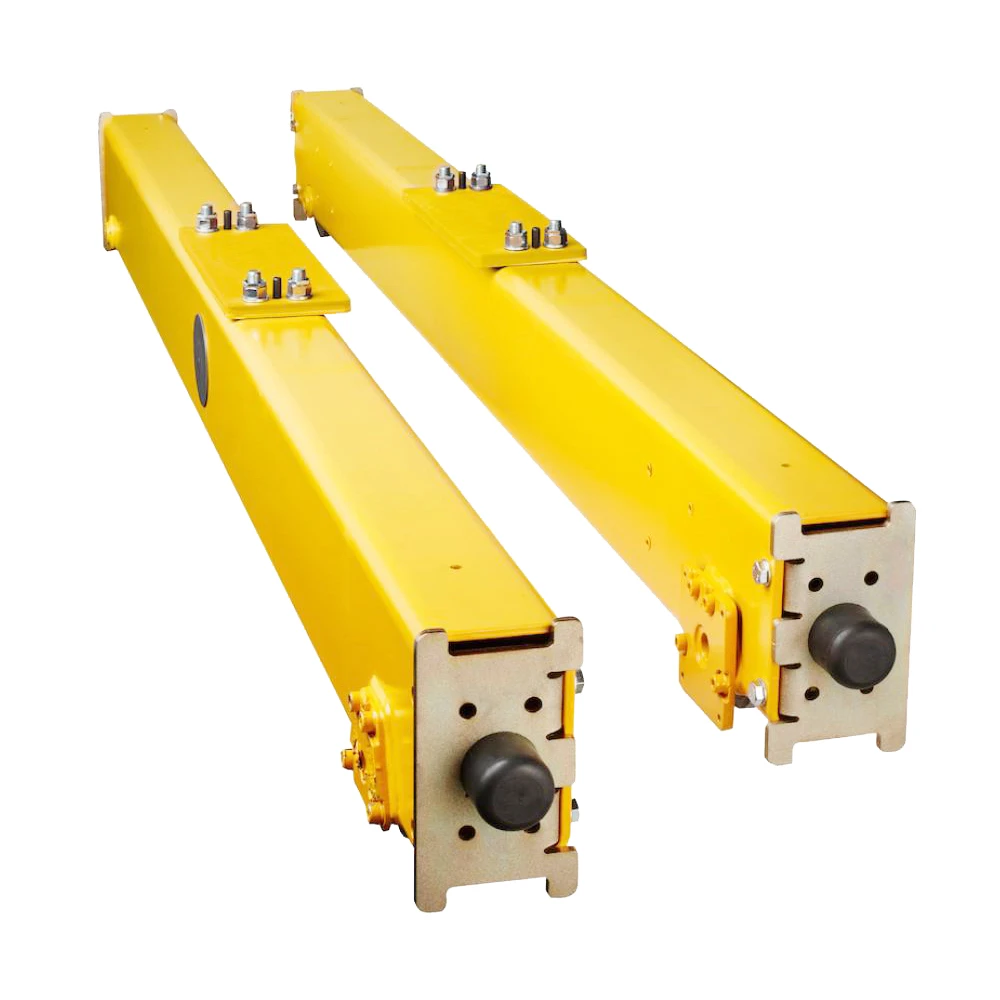
1) The end carriage of a Double Beam (or Double Girder) EOT (Electric Overhead Traveling) crane is a critical structural and functional component that supports the bridge girders and houses the wheels and drive mechanisms for crane movement.
End carriages are fabricated using high-strength steel to ensure structural integrity.Designed to support the weight of the double girders, the trolley, and the load being lifted.The end carriage has mounting points for connecting to the crane girders.Rigid and precise alignment ensures proper wheel contact and minimizes wear on rails.
The end carriage transfer the load of the crane to the rails and track beams. They ensure smooth and accurate longitudinal movement along the crane rails. They provide stability to the crane, especially during load movement.
The design and functionality of the end carriage significantly affect the crane's performance, efficiency, and safety. Proper installation, maintenance, and inspection ensure its long service life and reliability.
 |
 |
4.Crane travelling mechanism
1) Working principle
When the operator inputs a command to move the crane horizontally, the controller sends a signal to the drive motors to start.The electric motors start rotating, which is transferred through the gearbox to the travel wheels. The rotation of the wheels propels the crane bridge or trolley in the desired direction.The operator can control the speed and direction of the movement (forward or backward) using the controller. This is accomplished by adjusting the power sent to the motors.The travel wheels mounted on the crane bridge or trolley roll along the fixed runway rails, causing the entire crane structure to move horizontally.The load on the crane affects the speed at which it moves. Heavier loads may cause the crane to move more slowly, as the motor provides more torque to overcome the load's inertia.The crane's travelling system often includes limit switches to prevent the crane from moving beyond the track limits. Additionally, safety brakes are used to stop the crane in case of a power failure.
2) Functions of the crane operating mechanism
1. Horizontal Movement of the Crane
The primary function of the crane travelling mechanism is to provide horizontal movement of the entire crane along the length of the runway. This allows the crane to traverse from one end of the structure to the other, enabling it to cover the entire working area.
2. Lifting and Lowering Loads
While the double beam (or girder) crane is designed for vertical lifting and lowering through its hoisting mechanism, the travelling mechanism ensures that the crane can move to different positions to lift or place loads in various locations within its span.
3. Precise Positioning
The travelling mechanism ensures precise positioning of the crane over the load. It enables accurate lateral movement and helps position the load exactly where needed for lifting, loading, or unloading.
4. Smooth Operation
It provides smooth and continuous movement of the crane with minimal vibration. This is essential for the stability of the load being moved and for safe operations.
5. Support for the Crane Girders
The travelling mechanism supports the double-beam structure, ensuring that both beams remain properly aligned while moving along the runway. This ensures the structural integrity of the crane during operation.
6. Speed Control
The mechanism is designed with the ability to control the speed of movement. This is important for precise movements when handling heavy loads or when working in confined spaces.
7. Directional Control
The travelling mechanism enables the crane to move in both directions along the runway, typically forward and reverse. The control system ensures that the crane can change direction smoothly and without issue.
8. Braking and Stopping
The crane travelling mechanism is equipped with a braking system that helps to safely stop the crane after movement. This is essential for maintaining load control and preventing accidents.
9. Load Handling Over Long Distances
For applications where large distances need to be covered (such as in large industrial plants), the travelling mechanism ensures that heavy loads can be moved across these long distances safely and efficiently.
10. Safety Features
The mechanism is typically equipped with safety devices such as limit switches, emergency stop controls, and anti-collision sensors. These ensure the safe operation of the crane and prevent accidents due to unintended movement.
5.Trolley travelling mechanism
1) Structural composition
Trolley frame:The trolley frame is a robust structure that supports the hoisting mechanism and moves along the bridge beams. It is typically made of high-strength steel to withstand the loads encountered during crane operation.
Wheel set: The traveling wheels are mounted on the trolley and are designed to move along the bridge's beams or tracks.
Drive device: Variable speed control or inching controls are used to fine-tune the movement of the trolley, ensuring precise positioning.
2) Function of the trolley operating mechanism
Movement of the Trolley: The trolley is a key component of the crane that carries the hoisting mechanism (such as a hook or a lifting device) along the length of the crane's bridge. The traveling mechanism allows the trolley to move horizontally across the crane's beams (either I-beams or box girders) to position the load correctly over the desired location.
Horizontal Motion: The trolley's traveling mechanism provides the horizontal movement of the trolley along the bridge's beams. This movement is powered by an electric motor, usually with a variable speed control, ensuring that the trolley can travel smoothly over the span of the crane bridge.
Precise Positioning: The trolley traveling mechanism is designed to allow precise control over the movement of the hoist and load. This ensures accurate positioning of the load across the entire length of the bridge and is essential for operations such as lifting, lowering, or transferring materials.
Load Carrying Capacity: The traveling mechanism is designed to carry heavy loads and ensure that the trolley moves evenly across the entire span of the crane. The mechanism includes components like wheels, motors, reducers, and bearings, which are all built to handle the dynamic loads imposed by the crane's operations.
6.Crane wheel
1) Function of wheels
The wheels must be able to support the full weight of the crane and the load it is carrying, along with any dynamic forces resulting from movement.A crane wheel of a double beam EOT (Electric Overhead Traveling) crane is part of the crane's running mechanism that allows the crane to move along the bridge rails. These wheels are mounted on the end trucks of the crane, which are the parts that carry the weight of the crane and allow it to travel across the rails. In a double beam EOT crane, two main beams (the bridge) are supported by these wheels, with one set of wheels on each side of the crane.
2) Design requirements
Crane wheels are typically made of high-strength materials such as steel to withstand the heavy loads and continuous movement.They are often designed with flanges to ensure the wheel stays on track and avoids derailing. The wheels also have a hardened outer surface to prevent wear and tear.

7.Crane Hook
1) A Crane Hook of a Double Beam EOT (Electric Overhead Traveling) Crane is a critical component that is used to lift and lower loads. In a double beam EOT crane, the hook is typically suspended from two parallel beams (the main girders) and is operated by an electric hoist mechanism that moves along the beam system..
Crane hooks are made from high-strength steel alloys to support heavy loads.Typically, the crane hook is shaped like a "C" or a "J", with a point at the bottom to catch and secure the load.The size and strength of the hook depend on the lifting capacity of the crane. They are designed to carry loads ranging from a few tons to several hundred tons.
The hook is connected to a lifting mechanism, typically a wire rope or chain, powered by an electric hoist. This mechanism raises and lowers the hook as required to position or move the load.The hook is typically mounted on a trolley that moves along the crane's beams. The trolley is powered by an electric motor, allowing the hook to travel across the beam's length to pick up and deliver loads.Cranes usually have safety mechanisms to prevent lifting beyond the rated capacity of the hook and crane.

Motor
1)The motor of a Double Beam EOT (Electric Overhead Traveling) Crane plays a critical role in driving the various motions of the crane. In a typical double-beam EOT crane, there are usually three primary motions: hoisting, traveling (long travel and cross travel), and sometimes rotation (if it's a slewing crane).
2)Hoisting Motor: Usually a squirrel-cage induction motor (SCIM) or DC motor, depending on the design and power requirements. For precise control, a DC motor or a variable frequency drive (VFD)-controlled AC motor may be used.Typically ranges from 5 kW to 150 kW or more, depending on the capacity of the crane.
3) Traveling Motors (Long and Cross Travel):These motors control the horizontal movement of the crane along the long and cross rails of the overhead track. Long travel refers to the motion of the entire crane along the runway, while cross travel moves the trolley along the girder.Typically AC squirrel-cage induction motors for both long and cross travel, though DC motors may be used for smoother operation and variable speed control.

.
Sound and light alarm system & limit switch
1) Sound and light alarm system
Sound Alarm:Typically, a loud horn or siren is used.It is triggered for specific conditions, such as overloading, safety protocol breaches, or when the crane is in operation in sensitive areas (like near personnel or obstacles).The sound can be continuous or intermittent depending on the urgency.
Light Alarm (Visual Signal):Usually consists of flashing lights, LEDs, or strobe lights that are placed on the crane and at key locations in the vicinity.Different colors may be used to indicate different conditions. For example, red could indicate a critical issue like overload or malfunction, while yellow or orange could be used for cautionary alerts.The lights are typically mounted on the crane and can be visible from a distance, ensuring that personnel can see the warning even if they are not near the control panel.
2) Limit switch
A limit switch on a double beam EOT (Electric Overhead Traveling) crane is a safety device used to control the movement of the crane and ensure it doesn't exceed certain predefined limits, thus protecting the crane and its components from potential damage. The limit switch can be installed on various parts of the crane, such as the trolley, hoist, or bridge, to detect when the crane or its moving parts reach the end of their travel.
Hoist Limit Switch: This limit switch is used to prevent the hoist from over-lifting or over-lowering. It stops the hoisting mechanism when it reaches the maximum lifting height or ground position.
Trolley Limit Switch: Installed on the trolley, this switch ensures the trolley does not travel beyond the designated position along the bridge.
Bridge Limit Switch: Mounted at the ends of the crane's bridge, this switch prevents the entire bridge from traveling too far along the runway.
10.Safety Devices
1. Overload Protection Device
Purpose: Prevents the crane from lifting loads beyond its rated capacity, avoiding damage to the crane and hazards to operators.
Operation: Includes load sensors that activate an alarm or cut power to the hoist when an overload is detected.
2. Limit Switches
Types and Purpose:
Hoisting Limit Switch: Stops the hoist when the hook block reaches the upper or lower limit to avoid over-travel.
Trolley Limit Switch: Prevents the trolley from traveling beyond the designated track ends.
Crane End Limit Switch: Ensures the crane does not collide with the end stops of the runway.
3. Emergency Stop Buttons
Purpose: Allows operators to immediately stop the crane in case of an emergency.
Location: Usually located on the control panel, pendant, or radio remote.
4. Anti-Collision Devices
Purpose: Prevents collisions between multiple cranes operating on the same runway or with structures in the vicinity.
Mechanism: Uses sensors or proximity switches to maintain a safe distance.
5. Braking System
Types:
Electromagnetic Brakes: Engaged automatically in case of power failure.
Hydraulic Brakes: Provide additional safety for heavy loads and smooth stopping.
Purpose: Ensures controlled and safe stopping of the crane and trolley.
6. Buffers (Shock Absorbers)
Purpose: Installed at the ends of the crane runway and trolley track to absorb energy and minimize impact during accidental collisions.
7. Circuit Breakers and Fuses
Purpose: Protects the electrical systems of the crane from overcurrent or short circuits.
8. Load Indicators
Purpose: Displays the weight of the load being lifted to help operators stay within safe operating limits.
9. Wire Rope and Drum Guards
Purpose: Prevents the wire rope from slipping off the drum or pulley, reducing the risk of sudden load drops.
10. Over-speed Protection
Purpose: Prevents the hoist or trolley from exceeding safe operating speeds to avoid accidents.
11. Audible and Visual Alarms
Purpose: Alerts nearby personnel of crane movement or load lifting to enhance situational awareness.
12. Rail Clamps and Storm Brakes
Purpose: Secures the crane during high winds or when not in use, preventing movement due to external forces.
13. Fire and Heat Sensors
Purpose: Detects overheating of motor components or electrical systems to avoid fire hazards.
14. Operator Cabin Safety Features (If Equipped)
Purpose: Ensures the safety of the operator using features like insulated flooring, ergonomic controls, and emergency exits.
15. Maintenance Platforms and Handrails
Purpose: Provides safe access for maintenance and inspections on the crane.
11.Control Mode
1. Pendant Control
Features:A push-button station (pendant) hangs from the crane, usually connected by a cable.The operator stands on the ground or near the crane and uses the buttons to control the crane's movements.
2. Wireless Remote Control
Features:A handheld or wearable remote communicates wirelessly with the crane.The operator can control the crane from a distance, maintaining a safe working environment.
3. Cabin Control
Features:The operator sits inside a cabin mounted on the crane.Controls are located within the cabin, providing a direct line of sight for the operator.
4. Automated or Semi-Automated Control
Features:Uses programmable logic controllers (PLCs), sensors, and software to automate specific tasks.Operators may intervene for adjustments or emergency control.
5. Hybrid Control
Features:Combines two or more control methods (e.g., pendant and remote).Operators can switch based on operational requirements.

12.Sketch

Main technical

Advantages
1. Higher Load Capacity
Double beam EOT cranes can handle heavier loads compared to single beam cranes. The dual beams distribute the weight more effectively, making them suitable for lifting and moving large and heavy objects in industrial settings.
2. Larger Span
These cranes can cover a wider span and are ideal for large facilities, such as warehouses, steel plants, and manufacturing units, where long-distance material handling is required.
3. Greater Hook Height
The hook of a double beam crane can be positioned closer to the roof, allowing for a greater lifting height. This is beneficial in facilities with height constraints.
4. Enhanced Stability
The dual beams provide better stability, minimizing swaying and vibrations during operation. This ensures precise handling and positioning of materials.
5. Flexibility in Customization
Double beam cranes can be equipped with a variety of attachments, such as magnets, grabs, or tongs, to handle different types of materials like steel coils, slabs, or containers.
6. Durability and Longevity
The robust construction of double beam cranes makes them durable and capable of withstanding challenging working conditions, ensuring a longer lifespan with proper maintenance.
7. Higher Speed and Efficiency
The design of a double beam crane allows for faster hoisting and travel speeds, improving operational efficiency and reducing material handling time.
8. Better Load Distribution
The load is evenly distributed between the two beams, reducing stress on the crane structure and the building it is installed in.
9. Suited for Heavy-Duty Applications
These cranes are ideal for applications requiring continuous and heavy-duty operation, such as in foundries, shipyards, and construction industries.
10. Versatility in Application
Double beam EOT cranes can be designed for various configurations, including box girders or I-beam girders, depending on the specific needs of the operation.
Application:
1. Heavy Material Handling
Industries: Steel plants, power plants, shipyards, and foundries.
Purpose: Lifting and transporting heavy loads such as raw materials, machinery, or large components.
2. Assembly Lines
Industries: Automotive and manufacturing industries.
Purpose: Moving parts or assemblies across different stages of production.
3. Maintenance Operations
Industries: Power plants, oil refineries, and large workshops.
Purpose: Lifting and positioning heavy components like turbines, engines, or molds for maintenance or repairs.
4. Construction Projects
Purpose: Moving construction materials like beams, girders, and precast concrete components at construction sites.
5. Warehouse Management
Purpose: Storing and retrieving heavy inventory in large warehouses or storage facilities.
6. Steel Industry
Purpose: Handling and transferring heavy steel coils, sheets, and slabs efficiently.
7. Shipbuilding
Purpose: Lifting and positioning heavy ship parts, engines, and other components during construction or maintenance.
8. Mining Operations
Purpose: Transporting heavy mining equipment, ores, and other materials in underground or surface mining setups.
9. Energy Sector
Purpose: Managing heavy transformers, generators, and other power equipment in energy production and distribution facilities.
Crane production procedure
1. Design and Planning
Design Specifications: Detailed designs are created based on the crane's specifications (load capacity, span, lifting height, and working environment). This includes electrical schematics, mechanical drawings, and stress analysis.
Selection of Components: Components such as the hoist, trolley, beams, motors, and electrical panels are selected based on the design requirements.
2. Material Procurement
Steel: The main components such as the girders, beams, and supports are typically made from high-strength steel.
Motors and Electrical Components: Motors, hoists, controllers, limit switches, and other electrical parts are sourced from trusted suppliers.
Welding Materials: For joining metal components, suitable welding rods and consumables are procured.
3. Fabrication of Structural Components
Beam Fabrication: The crane beams (main girder) are fabricated by cutting, welding, and assembling steel plates into the required shape (I-beams, box girder, etc.).
Cross Girders and End Carriages: Fabrication of the cross girders and end carriages for the crane is done to connect the two main beams. These components will also be welded and machined.
Welding and Machining: All welded joints are inspected for quality and the structure is aligned. Machining is done for accurate fitting of the components.
4. Assembly
Assembly of Main Structure: The fabricated beams, cross girders, and end carriages are assembled into a complete crane structure. This is done using cranes or hoists in a controlled environment.
Trolley Assembly: The trolley, which houses the hoist, is assembled separately and then mounted on the crane's main girders. It includes components such as wheels, bearings, and the hoist mechanism.
Hoist Installation: The hoist, including the motor and gearbox, is installed on the trolley. This is the main lifting component, and it is aligned for smooth operation.
5. Electrical and Control System Installation
Wiring and Panels: Electrical panels, wiring, and control systems (such as remote control, limit switches, etc.) are installed. This includes connecting the crane's electrical components to the control system.
Motor and Drive Setup: The motors that power the crane's movement (hoisting, trolley, and bridge travel) are installed. Drives for speed control and safety features like overload protection are configured.
Safety and Sensors: Sensors, limit switches, and other safety features are integrated into the system to ensure safe crane operation.
6. Testing and Calibration
Preliminary Tests: Before commissioning, a series of static and dynamic tests are performed to check the mechanical and electrical components for functionality. This includes load testing, travel speed, and hoist functionality.
Calibration: The electrical system is calibrated to ensure proper functioning, including the setting of overload limits and travel limits.
7. Final Inspection and Quality Control
Inspection: All welds, joints, and components are inspected for quality and compliance with the design specifications.
Load Testing: The crane is tested under load conditions to ensure it can lift and move the specified load without any issues.
Documentation: All inspection reports, test results, and certification documents are prepared and verified.
8. Painting and Finishing
Surface Preparation: The crane is cleaned and treated for rust prevention. This involves sandblasting or grinding to prepare the surface.
Painting: The crane is painted with protective coatings to prevent corrosion and ensure a long service life. This can involve primer, topcoat, and anti-corrosion layers.
9. Delivery and Installation
Transportation: After fabrication and testing, the crane is dismantled (if necessary) and transported to the installation site.
Installation: The crane is assembled and installed on its rails or structure at the client's location. The installation team ensures proper alignment and secure mounting.
Final Commissioning: The crane is tested again on-site to confirm its performance under real working conditions.
10. Training and Handover
Operator Training: The client's operators are trained on the safe operation and maintenance of the crane.
Maintenance Instructions: Detailed maintenance guidelines are provided to the client, including inspection intervals, lubrication, and parts replacement.
11. Ongoing Support and Maintenance
Post-Commissioning Support: Some companies offer post-installation services, including routine maintenance, troubleshooting, and upgrades.
Workshop view:
The company has installed an intelligent equipment management platform, and has installed 310 sets (sets) of handling and welding robots. After the completion of the plan, there will be more than 500 sets (sets), and the equipment networking rate will reach 95%. 32 welding lines have been put into use, 50 are planned to be installed, and the automation rate of the entire product line has reached 85%.


Hot Tags: double beam eot crane, China double beam eot crane manufacturers, suppliers, factory, Eot Crane, Single Girder Overhead Crane Company, Double Girder Overhead Cranes
Previous
Single Beam Eot CraneYou Might Also Like


Send Inquiry