


QC Magnet Overhead Crane
Products Description
Key Features of QC Magnet Overhead Cranes
1. Electromagnetic Lifting System
Lifting Magnet (Electromagnet or Permanent Magnet) – Generates a strong magnetic field to pick up and transport ferrous materials.
Magnet Control Panel – Regulates power supply and demagnetization to ensure safe load release.
Backup Battery System – Prevents accidental load drops during power failures (critical for safety).
2. Robust Crane Structure
Heavy-Duty Girder & End Carriages – Designed to handle high-capacity loads (typically 1 ton to 50+ tons).
Reinforced Trolley & Hoist – Ensures smooth movement of magnetic loads.
3. Safety & Control Systems
Overload Protection – Prevents crane operation beyond rated capacity.
Emergency Stop & Anti-Sway System – Enhances operational safety.
Remote Control / Pendant Station – Allows precise load positioning.
4. Customizable Options
Explosion-Proof Version (QC-Ex) – For hazardous environments (e.g., flammable dust or gas areas).
Variable Frequency Drive (VFD) – Ensures smooth acceleration/deceleration.
Automated Operation – Can be integrated with PLC systems for smart factory applications.
QC Magnet Crane vs. Traditional Hook Crane
| Feature | QC Magnet Crane | Standard Hook Crane |
|---|---|---|
| Lifting Method | Electromagnet/Permanent Magnet | Hook & Sling |
| Material Type | Ferrous metals only | Any material |
| Speed | Faster (no slinging needed) | Slower (requires manual attachment) |
| Safety | No load slipping if power fails (with backup battery) | Risk of sling failure |
| Automation | Easily automated (PLC control) | Manual operation common |

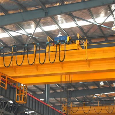
Pictures & Components
A QC magnet overhead crane consists of specialized components designed for lifting and transporting ferrous materials (steel plates, coils, scrap metal, etc.) using an electromagnetic or permanent magnet. Below is a detailed breakdown of its key components:
1. Main Structural Components
A. Bridge Girder
The primary load-bearing structure that spans the work area.
Made of heavy-duty steel (box girder or double girder) for high load capacity.
Designed to support the trolley, hoist, and magnet assembly.
 |
 |
B. End Carriages & Travel System
End carriages house the wheels and drive motors for crane movement along the runway rails.
Travel motors (explosion-proof if required) with brakes for smooth movement.
Buffers & bumpers to prevent collisions.
 |
 |
2. Lifting & Magnet System
A. Electromagnetic Lifter (or Permanent Magnet)
Electromagnet (requires power to generate magnetic field).
Permanent magnet (no power needed, but requires manual release mechanism).
Magnet control box regulates power supply and demagnetization.

B. Hoist & Trolley Unit
Hoist motor (explosion-proof if needed) with gearbox & drum.
Wire rope or chain for lifting/lowering the magnet.
Trolley frame moves horizontally along the bridge girder.
C. Magnet Power & Backup System
Cable reeling drum (for power supply to the magnet).
Backup battery unit (prevents load drops during power failure).

3. Electrical & Control System
A. Control Panel & Operator Interface
Main control panel (explosion-proof if required).
Pendant station (wired) or wireless remote control.
Variable Frequency Drive (VFD) for smooth speed control.

B. Safety & Limit Devices
Overload limiter (prevents exceeding crane capacity).
Limit switches (for upper/lower travel limits).
Emergency stop button.
Anti-sway system (for precise load positioning).
C. Power Supply & Wiring
Festoon system or cable reeling for power transmission.
Explosion-proof wiring & connectors (if used in hazardous areas).
.
![]()
4. Additional Optional Components
Weighing system (load measurement).
Automated positioning (PLC control).
Crane lighting (explosion-proof LEDs if needed).
Crane runway beams & rails (support structure).

Comparison: Electromagnet vs. Permanent Magnet
| Feature | Electromagnet | Permanent Magnet |
|---|---|---|
| Power Required | Yes (continuous) | No (but needs release mechanism) |
| Load Drop Risk | Only if power fails (backup battery helps) | No risk if properly engaged |
| Maintenance | Higher (electrical parts) | Lower (no power needed) |
| Best For | Frequent lifting/dropping | Long-term holding, scrap yards |

![]()
SKETCH

Main technical

Advantages
Key Advantages of QC Magnet Overhead Cranes
Exceptional Material Handling Efficiency
Instantly lifts ferrous materials without slings/chains, reducing loading/unloading time by up to 70%.
Handles irregularly shaped items (scrap metal, steel plates) that are difficult to grip mechanically.
Enhanced Safety
Eliminates manual load attachment risks (no workers under suspended loads).
Battery backup on electromagnets prevents accidental drops during power outages.
Spark-proof designs available for hazardous environments (ATEX/IECEx certified).
Cost-Effective Operation
Lower labor costs (requires 1 operator vs. 2-3 for sling-based lifting).
Minimal wear parts compared to mechanical grabs (reduced maintenance).
Precision & Control
Variable Frequency Drives (VFDs) enable smooth acceleration/deceleration.
Anti-sway systems and remote controls allow millimeter-level positioning.
Versatility
Swap magnets for different tasks (e.g., circular magnets for coils, rectangular for plates).
Can integrate with automated systems (Industry 4.0 ready).
Application:
Primary Applications
| Industry | Use Case | Benefit |
|---|---|---|
| Steel Mills | Moving coils, billets, plates | Prevents surface damage vs. mechanical grabs |
| Scrap Yards | Sorting/piling ferrous scrap | Handles tangled materials effortlessly |
| Foundries | Transporting molten metal molds | Heat-resistant magnet options available |
| Ports/Terminals | Loading steel cargo | 3x faster than hook-based systems |
| Automotive | Blanking press feeding | Precision placement of steel sheets |
Crane production procedure
1.Design and Engineering
Requirements Gathering:
Load capacity (e.g., 10T, 50T, 100T, etc.), span, lifting height, and operational environment are defined.
Customization needs are assessed, such as control modes (pendant, wireless, cabin) and special features (e.g., anti-collision, overload protection).
Preliminary Design:
Structural engineers and crane designers create the crane's initial design, including the main beam, end carriage, lifting system, trolley system, travel mechanism, and other components.
Calculation and Simulation:
Load calculations are performed to ensure the crane can handle the specified capacity.
Finite element analysis (FEA) may be used to simulate stresses and deflections in the structure to ensure safety and stability.
Detailed Design:
After approval, detailed drawings for each part are made, including the main girder, end carriage, hoist system, motors, control systems, and safety features.
2. Material Procurement
Raw Material Selection:
High-quality materials like steel, alloyed steel, forged steel, and electrical components are sourced according to specifications.
Materials are inspected for quality certification and compliance with industry standards (e.g., ISO, CE).
Component Sourcing:
Standard components such as motors, hoists, control panels, limit switches, and safety devices are sourced from reliable suppliers.
3. Fabrication of Components
Main Girder:
Cutting and welding of steel plates to form the bridge girder.
The girder is assembled by welding or bolting sections, ensuring it meets the required strength and precision.
End Carriage Assembly:
The end carriage is fabricated and assembled to hold the crane on the runway rails.
Wheel assemblies are installed to ensure smooth travel along the rails.
Hoist and Trolley System:
The hoist unit (electric or manual) is assembled, including the drum, wire rope, hook, and motor.
The trolley system is built to transport the hoist across the bridge, including trolley wheels and drive mechanisms.
Crane Traveling Mechanism:
The crane wheels are mounted on the end carriages, ensuring smooth horizontal movement.
The drive system is installed to control travel speed.
4. Assembly of Crane
Main Beam Installation:
The assembled main girder is lifted and positioned onto the end carriages.
The girder is aligned to ensure structural integrity.
Trolley and Hoist Installation:
The trolley system is mounted onto the main girder, and the hoist is mounted to the trolley.
The load chain or wire rope is installed and tested for smooth operation.
Travel Mechanism Setup:
The crane wheels are fitted, and the drive mechanism is connected to the control system for horizontal movement.
5. Electrical and Control System Installation
Wiring and Control Panel:
The control panel is installed and wired to manage all crane movements (hoisting, trolley, crane travel).
Limit switches, emergency stop buttons, and safety alarms are integrated into the control system.
Motor and Gear Installation:
Motors for hoisting, traveling, and the trolley are installed and connected to their respective gear systems.
Testing of Control Systems:
Control systems are checked to ensure proper integration of pendant control, wireless remote, or cabin control options.
6. Testing and Quality Control
Load Testing:
The crane undergoes static load testing (to check stability) and dynamic load testing (to check operational performance under actual working conditions).
Overload protection and limit switches are tested to ensure they function correctly.
Safety System Testing:
The sound and light alarms, limit switches, emergency stop buttons, and safety devices are all tested for functionality.
Movement Testing:
All movements-hoisting, trolley movement, bridge travel, and sway control-are tested for smooth operation and precision.
Electrical Testing:
All electrical components are tested for proper wiring, grounding, and communication between systems.
Documentation and Certification:
The crane is inspected according to international safety standards and undergoes certification by relevant authorities (e.g., CE, ISO).
Test certificates for motors, cranes, and load testing are prepared.
7. Final Inspection and Painting
Visual Inspection:
A thorough inspection is carried out to ensure that the crane meets design specifications and safety requirements.
Painting:
The crane is painted with high-quality anti-corrosion coatings to protect it from environmental conditions.
Marking and Labeling:
Safety labels, warnings, and capacity markings are applied to the crane for proper identification.
8. Delivery and Installation
Shipping:
The crane is carefully disassembled into transportable parts (if needed) and shipped to the customer's location.
Installation:
The crane is installed on-site, and all connections (power, mechanical, control) are made.
Final Commissioning:
The crane is commissioned by running it through a series of operational tests to ensure it works properly.
Operator training is conducted, if necessary, for safe and efficient use.
9. Post-Installation Support
Customer Training:
Operator training on how to use the crane safely and effectively.
Maintenance Schedule:
Providing a maintenance plan for the crane's continued operation, including regular inspections, lubrication, and testing.
After-Sales Support:
Offering spare parts, troubleshooting, and repair services.

Workshop view:
The company has installed an intelligent equipment management platform, and has installed 310 sets (sets) of handling and welding robots. After the completion of the plan, there will be more than 500 sets (sets), and the equipment networking rate will reach 95%. 32 welding lines have been put into use, 50 are planned to be installed, and the automation rate of the entire product line has reached 85%.


Hot Tags: qc magnet overhead crane, China qc magnet overhead crane manufacturers, suppliers, factory, Double Girder Overhead Crane, Double Girder Overhead Travelling Crane
You Might Also Like


Send Inquiry