










European Double Girder Bridge Crane
Products Description
DEFINING CHARACTERISTICS & PHILOSOPHY
Core Engineering Principles
Precision Over Tolerance: Components are manufactured to tighter tolerances than minimum standards require (e.g., wheel alignment within 0.5mm over span).
Lifecycle Engineering: Designed for 25-40+ years of reliable service with documented maintenance plans.
System Integration: Holistic design where mechanical, electrical, and control systems are engineered as a unified system.
Preventive Safety: Multiple redundant safety systems prevent failures rather than just mitigate them.
Manufacturing Excellence
Premium Materials: Standard use of S355J2+N steel (with impact testing at -20°C), stainless steel fasteners, and marine-grade aluminum for enclosures.
Advanced Fabrication: Laser/plasma cutting with robotic welding for critical joints (welding procedures qualified to EN ISO 15614).
Surface Technology: Multi-stage surface preparation including zinc phosphate pretreatment before powder coating or wet paint application.
PERFORMANCE BENCHMARKS
| Parameter | European Premium | Standard Industrial |
|---|---|---|
| Positioning Accuracy | ±1-3mm | ±10-20mm |
| Speed Control Range | 1:1000 (0.1-100%) | 1:100 (1-100%) |
| Noise Level | ≤65 dB(A) at 1m | ≤75 dB(A) at 1m |
| Energy Efficiency | Regenerative drives (saves 20-30%) | Resistive braking (energy wasted as heat) |
| Mean Time Between Failures (MTBF) | 5,000+ hours | 2,000-3,000 hours |
| Installation Time | 30-40% faster (modular design) | Standard assembly time |
Core Components:Bearing, Gearbox, Motor, Pump
Place of Origin:Henan, China
Warranty:1 Year
Weight (KG):2000 kg
Video outgoing-inspection:Provided
Machinery Test Report:Provided
Design:Double beam
Effectiveness:high efficiency
Operating speed:High speed operation
Stability:Anti-swing function
Color:Optional
Power Source:110V/220V/230V/380V/440V,customized
Span:7.5-31.5m

Pictures & Components
1. BRIDGE STRUCTURE SYSTEM
Main Girders (Tragbalken)
Construction: Welded box girders with optimized cross-section (typically 1:1.2 to 1:1.5 height-to-width ratio)
Material: S355J2+N/K2 steel plates (EN 10025-2) with guaranteed -20°C impact toughness
Internal Structure:
Transverse diaphragm plates every 1.5-2m
Longitudinal stiffeners on web and flanges
Diagonal bracing in corners for torsional rigidity
Welding: Submerged arc welding (SAW) for main seams, MAG welding for stiffeners
Quality Control: 100% ultrasonic testing of critical welds, magnetic particle testing for non-critical welds

End Trucks (Laufkatzen)
Frame Construction: Welded box section with integrated motor/platform brackets
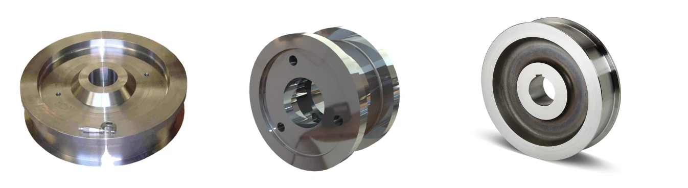
Wheel Assemblies:
Double-flanged forged steel wheels (34CrNiMo6 material)
Induction-hardened tread (55-60 HRC to 8mm depth)
Spherical roller bearings (FAG/SKF/INA) with labyrinth seals
Hydraulic jacking points for wheel replacement
Connection to Girders: High-strength friction-grip bolts (HV system per EN 14399-10)
Runway System (Laufbahn)
Rails: EN 14811-1 A75-A120 crane rails with EN 13674-1 profiles
Fastening: Spring-loaded rail clamps (GANTREX, RÜBIG) allowing thermal expansion
Alignment: Laser-leveled to ±1mm over 20m, ±2mm total span
 |
 |
2. TROLLEY SYSTEM (FAHRWERK)
Trolley Frame
Design: Welded steel construction with integrated gearbox/motor mounts
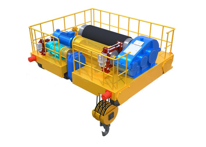
Wheel Arrangement: 8-wheel configuration (4 driven, 4 idler) for load distribution
Wheels: Case-hardened (60-62 HRC) with crowned tread for rail alignment
Trolley Drive System
| Component | European Specification |
|---|---|
| Motor | IEC frame (e.g., 160M) with IE4 premium efficiency, brake motor optional |
| Gearbox | Helical-bevel units (SEW, Nord, Flender) with ≥1.25 service factor |
| Coupling | Elastic pin/bush type (R+W, KTR) with fail-safe design |
| Brake | Spring-applied, electrically released disc brake (SBG, Mayr) |
 |
 |
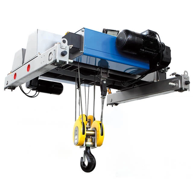
3. HOISTING SYSTEM (HEBEWERK)
Main Hoist Unit
Drum Assembly:
Machined steel drum with undercut grooves for rope guidance
Rope retention system (EN 13135 compliant)
Integral rope guide with proximity sensor
Gearing: 3-stage planetary/helical gearbox with ≥1.4 service factor
Motor: Dual-speed or VFD-controlled with Class F insulation (155°C)
Braking: Dual independent systems:
Motor brake: Disc brake on high-speed shaft
Safety brake: Mechanical load brake on gearbox output
Rope System
Wire Ropes: 19x7 or 35x7 IWRC rotation-resistant (Casar, Pfeifer, Kiswire)
Sheaves: Forged steel with hardened grooves (55-60 HRC)
Terminations: Wedge sockets with load monitoring pins
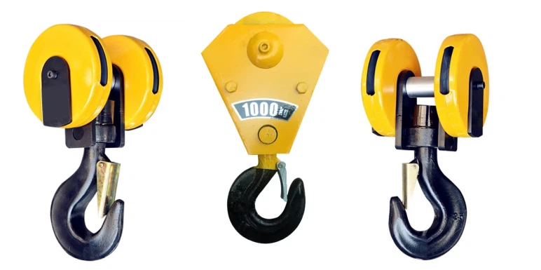
Load Handling Attachments
Hook Block: Forged steel hooks (Grade T or V per EN 1677-1)
Grab System (if equipped):
Motorized grabs with IP67-rated internal motors
Rope-operated grabs with separate closing mechanism
Load cells integrated in spreader beam
4. ELECTRICAL & CONTROL SYSTEMS
Power Supply System
Conductor System: Insulated conductor bars (DUCT-O-BAR, ALU-TRAK) with:
Self-cleaning collectors
Phase indication markers
Expansion joints every 40-60m
Cable Management: Energy chains (igus, Kabelschlepp) for trolley movements
Safety & Monitoring Components
| Device | Standard | Function |
|---|---|---|
| Load Limiter | EN 13155 | 2-channel system with cross-checking |
| Limit Switches | EN 60947-5-1 | Magnetic proximity type with manual reset |
| Encoder Systems | EN 61508 | Absolute multi-turn for hoist, incremental for travel |
| Anti-Collision | EN 12999 | Laser/LiDAR based with warning/stop zones |
| Anemometer | EN 61400-12-1 | Cup/vane type with 4-20mA output |
Electrical Cabinets
Construction: Powder-coated steel (RAL 7035) with IP54/IP55 rating
Internal Layout: Form 3b/4 segregation (EN 61439-1/2)
Components:
Main circuit breaker with RCD protection
Line filter for EMC compliance
24V DC UPS for safety circuits
PLC with SD card for data logging

5. GRAB BUCKET SYSTEM (SPECIALIZED)
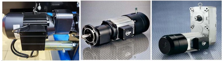
Motorized Grab Components
Head Assembly:
Gearmotor: Brake motor (SEW/Bauer) with IP67 protection
Gearbox: Planetary reducer with 150-300:1 ratio
Torque limiter: Mechanical slip clutch to prevent overload
Jaw Mechanism:
Jaws: Hardox 500 wear plates with replaceable teeth
Hinges: Bushed pins with automatic lubrication
Seals: Multi-lip radial seals to retain grease
Electrical System:
Slip ring assembly: Fiber brush technology for power transfer
Temperature sensors: In motor and gearbox
Position sensors: For jaw opening angle
Rope-Operated Grab Components
Closing Mechanism: Differential pulley system for mechanical advantage
Rope Guides: Self-aligning sheaves to prevent rope twisting
Weight Optimization: Counterweights for empty grab stability
6. AUXILIARY & SPECIAL COMPONENTS
Lubrication System
Centralized automatic lubrication (Lincoln/Trafo) for:
Wheel bearings
Open gear meshes
Rope sheave bearings
Progressive divider valves for precise oil distribution
Monitoring & Diagnostics
Vibration sensors: On all major bearings (SKF/ifm)
Temperature sensors: Motors, gearboxes, brakes
Oil condition sensors: In gearboxes
Wear sensors: On brake linings
Data gateway: MQTT/OPC UA interface to plant network
Special Environment Components
| Environment | Special Components |
|---|---|
| Cold (-40°C) | Low-temperature steel, heated bearings, Arctic grease |
| Corrosive | AISI 316 stainless fasteners, zinc-aluminum coating |
| Explosive | ATEX-certified motors, brakes, sensors |
| Clean Room | Stainless steel, smooth surfaces, positive pressure |

7. MATERIALS & FINISHES
Surface Protection System
Preparation: Sa 2.5 blasting to 50-75μm profile
Priming: Zinc-rich epoxy (80μm dry film thickness)
Intermediate: Micaceous iron oxide epoxy (125μm DFT)
Topcoat: Polyurethane (50μm DFT) in RAL colors
Critical Material Specifications
Structural Steel: EN 10025-2 S355J2 (with CE marking and 3.1 certificate)
Fasteners: EN 15048-1/2 HV system bolts, A4-80 stainless for corrosive areas
Electrical: Harmonized cables (H07RN-F) with low smoke zero halogen option
Bearings: ISO 281 L10 life calculation ≥100,000 hours
8. QUALITY DOCUMENTATION PER COMPONENT
Each major component includes:
Material certificates (3.1 or 3.2 per EN 10204)
Welding procedure qualifications (WPQR)
Non-destructive testing reports
Dimensional inspection reports
Factory acceptance test protocols
CE Declaration of Incorporation
Sketch

Main technical

Advantages
1. Engineering & Performance Superiority
| Advantage | Technical Implementation | Impact |
|---|---|---|
| Precision Engineering | FEA-optimized box girders (L/1000 deflection), laser-aligned components (±1mm tolerance) | Ultra-smooth operation, minimal vibration, extended component life |
| Predictable Performance | Statistical process control, component matching, system integration | Consistent operation within specifications for entire lifecycle |
| Advanced Motion Control | VFDs on all motions with CANbus synchronization, anti-sway algorithms | Pinpoint positioning (±2mm), shock-free load handling |
| Superior Longevity | Premium materials (S355J2+N), corrosion protection (C5-M), precision bearings | 30-40+ year design life with 90%+ uptime |
2. Safety & Reliability Excellence
Multi-layer Safety Systems:
• Primary: Load limiters (2-channel), limit switches (magnetic)
• Secondary: Underspeed detection, emergency stop (Category 0/1)
• Tertiary: Structural overload protection, anti-collision systems
Fail-Safe Design: Dual independent brakes, redundant PLCs, safety-rated components (SIL2/PLd)
Predictive Maintenance: Integrated sensors (vibration, temperature, wear) with cloud analytics
Documented Reliability: MTBF >5,000 hours, 99.5%+ availability in continuous operation
3. Operational Efficiency
| Efficiency Area | European Technology | Result |
|---|---|---|
| Energy Efficiency | Regenerative VFDs (feed 20-30% back to grid), IE4 motors, LED lighting | 40-60% lower energy cost vs. conventional cranes |
| Maintenance Efficiency | Centralized lubrication, quick-change components, diagnostic ports | 50% less maintenance time, 70% fewer unplanned stops |
| Space Optimization | Compact design, high hook approaches, minimal deflection | Maximum usable floor/height space |
| Speed & Productivity | Optimized acceleration profiles, simultaneous motions | 15-25% faster cycle times |
4. Economic Advantages
Higher Residual Value: 60-70% after 10 years vs. 20-30% for standard cranes
Insurance Benefits: 20-40% lower premiums due to certified safety systems
Regulatory Compliance: Zero non-compliance risks in European markets
5. Technological Leadership
Digital Integration: OPC UA, MQTT interfaces for Industry 4.0 integration
Smart Features:
• Digital Twin: Virtual model for simulation and optimization
• Predictive Analytics: AI-driven failure prediction
• Remote Diagnostics: Secure manufacturer access for troubleshooting
Future-Proofing: Modular design allowing technology upgrades
Application:
1. Automotive & Advanced Manufacturing
Automotive Assembly Lines
Requirements: High precision (±2mm), clean operation, 24/7 reliability
European Advantages: Vibration-damped trolleys, absolute encoders, white room variants
Specific Uses:
• Body-in-white handling: High-precision positioning for welding stations
• Battery production: Cleanroom cranes for lithium-ion cell handling
• Paint shops: Explosion-protected cranes with special finishes
Aerospace Manufacturing
Applications: Wing assembly, fuselage joining, engine handling
Critical Needs: Micro-positioning (±0.5mm), anti-sway, variable geometry handling
European Solutions:
• Active load control: Counter-mass systems for delicate components
• 6-axis positioning: Combined bridge/trolley/hoist/rotation/tilt control
• Carbon fiber handling: Static-dissipative systems
2. Energy & Heavy Industry
Power Generation
| Plant Type | Application | European Features |
|---|---|---|
| Nuclear | Fuel rod handling, maintenance | SIL3 safety systems, seismic qualification, radiation-resistant materials |
| Thermal | Coal/biomass handling | High-duty grabs (FEM 8m), dust-proofing, automated blending |
| Hydro | Turbine maintenance | High-capacity (500T+), precision lowering, remote operation |
Steel & Metals
Scrap Yards: 24/7 operation with 50T+ magnet or grab handling
Aluminum Smelters: Hot metal handling (up to 400°C) with heat shielding
Special Features:
• Spark-resistant components for explosive atmospheres
• High-cycle designs for continuous casting applications
• Automated inventory management with RFID tracking
3. Logistics & Infrastructure
Ports & Intermodal Terminals
Container Handling: Spreader cranes with automatic twistlock systems
Bulk Terminals: Grab cranes with automated stockpile management
European Advantages:
• Wind-resistant design: EN 13001-2 compliance for 150km/h winds
• Saltwater corrosion protection: C5-M coating, stainless components
• Remote operation: Operator centers with VR integration
Rail & Transportation
Locomotive Maintenance: Under-bridge cranes for engine handling
Tunnel Construction: Segment handling with millimeter precision
Bridge Construction: Launching gantries with synchronized multi-crane control
4. Process Industries
Chemical & Pharmaceutical
Clean Room Applications: Stainless steel (AISI 316L) construction, IP65 sealing
Hazardous Areas: ATEX-certified complete packages (Zone 1/21)
Precision Features:
• Vibration isolation: Air-spring mounted hoists for sensitive processes
• Contamination control: Smooth surfaces, positive pressure enclosures
• Weight batching: Integrated load cells with 0.1% accuracy
Food & Beverage
Hygienic Design: USDA/FDA compliant materials, easy-clean surfaces
Automation: Fully automated pallet/case handling with vision systems
Temperature Zones: Freezer applications (-40°C) with cold-proof components
5. Specialized Applications
Research & High-Tech
Particle Accelerators: Non-magnetic cranes (aluminum construction)
Semiconductor Fabs: Vibration class VC-D/E, ESD protection
Observatories: Ultra-smooth motion for telescope components
Disaster Response & Specialized Handling
Nuclear Decommissioning: Remote-operated cranes with camera systems
Art & Museum Handling: Micro-speed control (0.1 m/min), climate control
Shipbuilding: Gantry cranes with 1000T+ capacity for block assembly
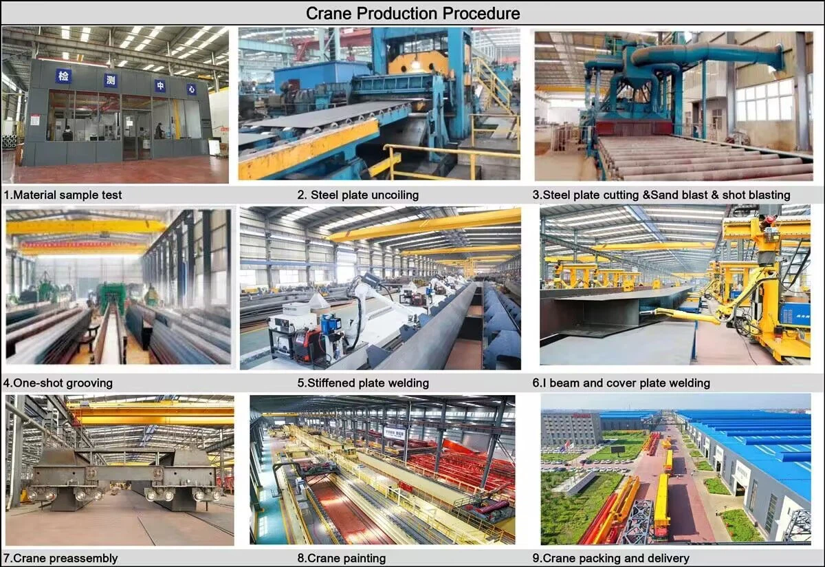
Crane production procedure
Phase 1: Design and Engineering
This is the foundational phase before any physical work begins.
Customer Requirements Analysis: Engineers review the specific requirements: capacity (e.g., 32/5 tons), span, lifting height, duty class (e.g., A5, A6), and any special needs (e.g., explosion-proof, high-temperature environment).
Structural Design: Using CAD (Computer-Aided Design) software, engineers design the main girders, end carriages, and trolley frame. Finite Element Analysis (FEA) is often used to simulate stress, deflection, and dynamic loads to optimize the design for strength and weight.
Mechanical and Electrical Design: This includes selecting and designing the drive systems (motors, gearboxes, wheels), the hoisting mechanism, and the complete electrical control system with panels, variable frequency drives (VFDs), and safety devices.
Bill of Materials (BOM) Creation: A detailed list of all raw materials (steel plates, profiles) and purchased components (hoist, motors, brakes, wire rope, wheels) is generated.
Phase 2: Raw Material and Component Procurement
Steel Plates and Profiles: High-quality steel plates (typically Q235B or Q345B according to Chinese standards, equivalent to S235JR/S355JR) are procured in required dimensions and thicknesses.
Purchased Components: Critical components are sourced from reputable suppliers. These include:
Hoist unit (may be manufactured in-house or purchased)
Electric motors for bridge and trolley travel
Reducer gearboxes
Wheels and axles
Brakes
Electrical components (controllers, contactors, limit switches, VFDs, cabling)
Bearings
Phase 3: Main Steel Fabrication & Machining
This is the core of the manufacturing process.
1. Main Girder Fabrication:
Cutting: Steel plates are cut to the required size and shape using CNC plasma or flame cutting machines for high precision.
Web/Flange Preparation: The vertical web plates and horizontal top/bottom flange plates are prepared. For long spans, the girders are often designed as a tapered "I-beam" profile (wider in the middle) to optimize strength-to-weight ratio.
Assembly and Welding: The girders are assembled on large jigs to ensure straightness and correct camber (a pre-set upward bend to counteract deflection under load). This is a critical step. Submerged Arc Welding (SAW) is commonly used for its deep penetration and high-quality, consistent welds on long seams.
Stress Relieving: After welding, the main girders often undergo stress relieving heat treatment in a large furnace. This process removes internal stresses created during welding, preventing future distortion and ensuring dimensional stability.
Machining: The mating surfaces for the end carriages and trolley rails are machined using a planer or milling machine to ensure a perfectly flat and level surface.
2. End Carriage (End Truck) Fabrication:
The end carriages are fabricated from steel sections and plates.
They house the wheels, drive motors, and gearboxes for the bridge movement.
The wheel bases are drilled and machined to precise tolerances to ensure proper alignment and that all wheels make contact with the runway rails.
Phase 4: Mechanical Assembly
1. Bridge Assembly:
The two main girders are positioned parallel to each other and connected to the end carriages using high-strength bolts or by welding, forming the complete bridge structure.
The trolley rails are precisely aligned and bolted onto the top of the main girders.
2. Trolley Frame Assembly:
The trolley frame is assembled, and its wheels, drives, and the main hoisting unit (including the wire rope drum, motor, gearbox, and hook block) are mounted onto it.
3. Drive System Installation:
The travel drive units (motor, gearbox, coupling) are installed on the end carriages (for bridge motion) and on the trolley frame (for trolley motion).
All mechanical components are aligned to prevent binding and premature wear.
Phase 5: Electrical System Installation
Cable Reeling System: The main power supply system for the crane (e.g., conductor bars or festoon systems) is installed along the bridge girder.
Control Panel Installation: The main control panel, VFDs, and other electrical components are mounted in a protected enclosure, usually on the bridge girder.
Wiring: All motors, brakes, limit switches, and safety devices are wired according to the electrical schematic.
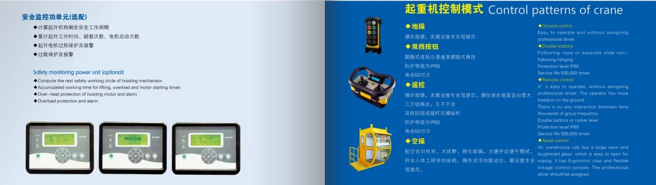
Operator Control Station: The pendant control station (hung from the crane) or a radio remote control system is connected and tested.
Phase 6: Surface Treatment and Painting
Surface Preparation: The entire crane structure is shot-blasted to remove mill scale, rust, and welding slag, creating a clean, rough surface for optimal paint adhesion.
Priming: A rust-inhibitive primer is applied immediately after blasting to prevent oxidation.
Painting: Multiple coats of high-quality industrial enamel paint are applied. Color is often according to customer specification or standard factory practice (e.g., international orange/yellow for visibility). The painting process protects the crane from corrosion in industrial environments.
Phase 7: Factory Acceptance Testing (FAT)
Before disassembly for shipment, the fully assembled crane undergoes rigorous testing.
Visual Inspection: Checking dimensions, weld quality, and assembly.
No-Load Test: Running the crane, trolley, and hoist in all directions to verify smooth operation, correct speed, and functionality of all controls and limit switches.
Static Load Test: The hoist is lifted with a test load 25% greater than the rated capacity (as per FEM/ISO standards). The load is held for 10-15 minutes to check for structural deformation, weld integrity, and brake holding capacity.
Dynamic Load Test: The crane is operated with a test load 10% greater than the rated capacity. All motions are tested to ensure performance under dynamic stress.
Electrical Safety Tests: Insulation resistance, grounding continuity, and proper functioning of all emergency stops and safety circuits are verified.
Phase 8: Dismantling, Packaging, and Shipping
After passing FAT, the crane is carefully dismantled into transportable sections (main girders, end carriages, trolley, electrical panels).
All components are professionally packaged and protected against damage during transit.
They are shipped to the customer's site, where they will be reassembled and installed by technical crews.
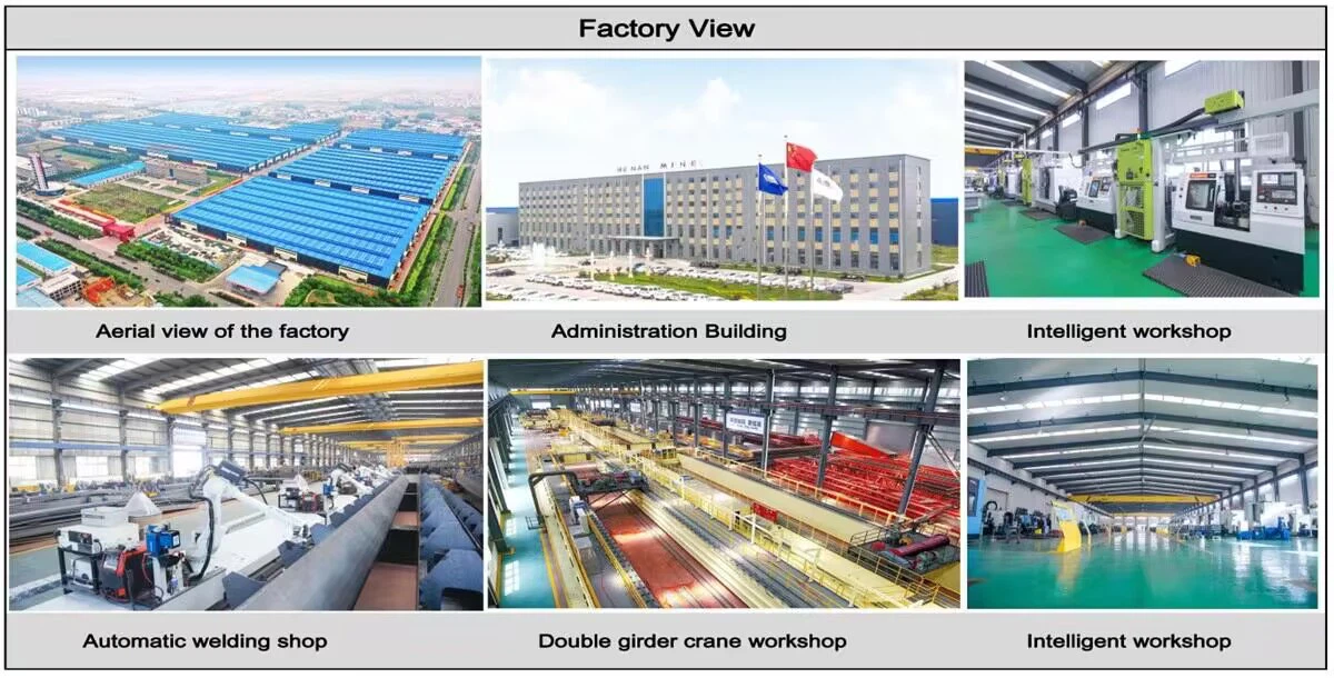
Workshop view:
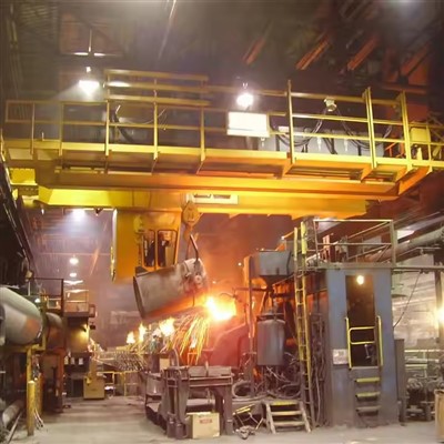
The company has installed an intelligent equipment management platform, and has installed 310 sets (sets) of handling and welding robots. After the completion of the plan, there will be more than 500 sets (sets), and the equipment networking rate will reach 95%. 32 welding lines have been put into use, 50 are planned to be installed, and the automation rate of the entire product line has reached 85%.


Hot Tags: european double girder bridge crane, China european double girder bridge crane manufacturers, suppliers, factory, Double Girder Overhead Travelling Crane, Double Girder Overhead Crane
You Might Also Like



Send Inquiry