


40T Double Girder Overhead Crane
Products Description
A 40-ton (40,000 kg / 88,000 lbs) Double Girder Overhead Crane is a type of EOT (Electric Overhead Traveling) crane where the hoist trolley runs on top of two parallel bridge girders. These girders are supported by end trucks that travel along runway beams mounted on the building columns or freestanding supports.
Comparison: QE vs. Other Overhead Cranes
| Feature | QE Type (Standard Electric) | QL Type (Light Duty) | QC Type (Severe Duty) |
|---|---|---|---|
| Duty Cycle | M3/M4 (Medium/Heavy) | M2/M3 (Light/Medium) | M6/M7 (Severe/Very Severe) |
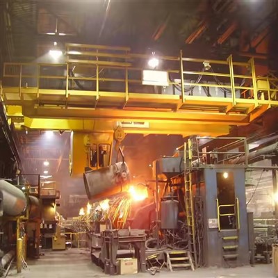
| Typical Use | General Manufacturing, Warehouses | Workshops, Light Assembly | Steel Mills, Foundries |
| Operation | Electric | Electric or Manual | Electric |
| Robustness | Standard Industrial | Light-Duty | Heavy-Duty |
Conclusion: The QE Overhead Crane is the backbone of countless industrial facilities. Its electric operation, standard-duty design, and versatile configuration options make it a practical, efficient, and reliable choice for the vast majority of material handling tasks that require more than just occasional light lifting. It is the go-to solution for businesses seeking to improve productivity with a dependable and cost-effective overhead lifting system.
Core Components:Bearing, Gearbox, Motor, Pump
Place of Origin:Henan, China
Warranty:1 Year
Weight (KG):4000 kg
Video outgoing-inspection:Provided
Machinery Test Report:Provided
Design:Double beam
Effectiveness:high efficiency
Operating speed:High speed operation
Stability:Anti-swing function
Color:Optional
Power Source:110V/220V/230V/380V/440V,customized
Span:7.5-31.5m

Pictures & Components
1. Bridge Structure
This is the primary load-bearing framework.
Main Girders (2): The primary longitudinal beams, typically of box-section design for heavy-duty applications like 40T. They are welded for strength and rigidity.
End Trucks (2): Located at each end of the bridge, they house the wheels, drives, and connection points to the girders.
 |
 |
Brakes: Mounted on the drive motors to stop bridge motion.
Reducers/Gearboxes: Step down motor speed to appropriate wheel speed.
Wheels (4 or 8): Forged steel wheels that ride on the runway rails. A 40T crane often has 4-wheel end trucks, but may use 8 (two per corner) for very high capacity or span.
 |
 |
Bridge Drive System: Powers the longitudinal travel (crane movement).
Drive Motors (2): One motor per end truck, synchronized for straight travel.

2. Hoist Trolley
The unit that carries the hoist and moves transversely on the bridge girders.
Trolley Frame: A rigid steel frame with wheels that runs on rails mounted on the top of the bridge girders.
Trolley Drive System:
Drive Motor: Powers transverse travel (trolley movement).
Reducer/Gearbox: Similar to bridge drive.
Wheels: Typically 4 or more, running on the bridge girder rails.
Main Hoist Unit: The core lifting mechanism.
Hoist Motor: High-power AC motor with a dedicated hoist brake (often a fail-safe disc brake).
Hoist Reducer/Gearbox: High-ratio gearbox to convert motor speed into powerful drum rotation.
Drum: A large steel cylinder onto which the wire rope is wound. Grooved for proper rope spacing.
Wire Rope: Multiple strands, high-grade steel, sized for 40T+ with a large safety factor (e.g., minimum 6:1).
Hook Block: The assembly that connects to the load. For 40T, this is a multiple-sheave block (e.g., 4 or 5 sheaves) to reduce the rope load through reeving. Includes a heavy-duty forged steel hook with a safety latch.
Auxiliary Hoist (Optional but common on 40T): A smaller, faster hoist (e.g., 5T or 10T capacity) mounted on the same trolley for lighter loads, increasing versatility.

3. Runway System
The fixed infrastructure.
Runway Beams: Typically heavy-duty steel I-beams or fabricated box beams attached to the building columns or a dedicated support structure.
Runway Rails: Standard crane rails (e.g., A120, QU100 profile) securely fastened to the runway beams.
Rail End Stops: Physical buffers at both ends of the runway to prevent over-travel.
Conductor Systems: Deliver power to the moving crane.
Main Feeder: For the bridge drive. Can be Festoon System (cable trolleys on an I-beam) or Enclosed Conductor Bar (isolated bars in a housing).
Trolley Feeder: Supplies the hoist trolley, often using a Festoon or Cable Reel.


4. Electrical & Control Systems
Main Power Supply: High-amperage AC supply (e.g., 415V/3 Phase/50Hz or 480V/3 Phase/60Hz) via a Main Disconnect Switch or Circuit Breaker on the bridge.
Control Cabin/Cab (Optional): An operator's cabin suspended from the bridge. Common for heavy-duty, frequent-use 40T cranes.
Pendant Station (Alternative): A handheld or floor-mounted push-button station for ground control via a low-voltage control cable.
Radio Remote Control (Common Modern Choice): Allows wireless operation from the floor, providing the operator with mobility and the best vantage point.
Control Panel/Enclosure: Houses contactors, variable frequency drives (VFDs - essential for smooth, controlled acceleration and precise load handling on a 40T crane), PLC (Programmable Logic Controller), and overload protection devices.
Limit Switches:
Hoist Upper/Lower Limit: Automatically cuts power at the top and bottom safe limits.
Bridge & Trolley Travel Limits: Prevents the crane or trolley from hitting the end stops.
Anemometer (if outdoors): Wind speed sensor that alarms and disables crane operation in high winds.

5. Safety Components (Critical for 40T)
Overload Limiter: A mandatory and critical device that measures the actual load on the hook and prevents lifting beyond 105-110% of rated capacity (40T).
Anti-Collision Systems: Sensors to prevent collisions between multiple cranes on the same runway.
Warning Devices: Rotating beacon and audible alarm (horn/bell).
Emergency Stop Buttons: Located at multiple accessible points.
Walking Platforms & Ladders: For safe inspection and maintenance access along the bridge and to the trolley.
Fire Resistant Fluids: In hydraulic systems (if applicable for brakes or other functions).

Sketch

Main technical

Advantages
Primary Advantages (vs. Single Girder Cranes)
Higher Lifting Capacity & Better for Heavy Duty Use: The twin bridge girders distribute the load more evenly, making the 40T capacity the starting point for robust double girder designs. They are inherently built for severe service and frequent use.
Greater Hook Height/Lift: The hoist trolley runs on top of the girders, not underneath them. This design maximizes the critical distance between the hook and the crane runway, allowing you to lift loads higher in your building-utilizing the full height of your facility.
Longer Span Capability: Double girders are far more rigid, allowing them to span greater distances between runways (often 30+ meters/100+ feet) without excessive deflection (sagging). This is essential for covering wide workshops or warehouses.
Improved Hook Approach: The trolley can travel side-to-side (cross travel) to the very ends of the girders. Combined with the long travel of the entire crane, this allows the hook to reach almost every corner of the building floor, minimizing "dead" areas.
Heavier Duty Trolley & Hoist: Designed to accommodate larger, more powerful motorized trolleys and hoists. This allows for:
Auxiliary Hoists: Easily adding a smaller, secondary hoist (e.g., 5T or 10T) for frequent lighter lifts.
Specialized Lifting Attachments: Integration of grabs, magnets, or vacuum lifters is more straightforward.
Operational & Performance Advantages
Higher Duty Cycle & Durability: Built with more robust components (wheels, drives, brakes), they are designed for Class C (Moderate) to Class F (Continuous Severe) service. They can handle more lifts per hour, longer running times, and harsher environments.
Smoother & More Precise Movement: The dual end trucks (on each side) provide superior stability and alignment, resulting in smoother travel, less load sway, and more precise positioning-critical for sensitive or valuable loads.
Reduced Deflection & Vibration: The box-girder construction offers significantly higher rigidity. This means less vertical deflection (sag) when lifting and less lateral skewing during travel, leading to safer and more controlled operations.
Enhanced Safety Features: The robust structure more easily accommodates advanced safety systems like:
Anti-Collision Systems for multiple cranes.
Overload protection in multiple zones.
Magnetic runway collectors for more reliable power delivery.
Walkways & maintenance platforms along the girders for safer servicing.
Lower Long-Term Operating Costs: While the initial investment is higher than a single girder crane, the durability, reduced maintenance downtime, and longer lifespan of a properly specified double girder crane lead to a lower total cost of ownership over 20+ years.
Flexibility for Future Needs: Often designed with a 10-15% capacity margin. This "built-in" headroom can accommodate future process changes or slightly heavier loads without requiring a completely new crane.
Application:
Key Application Areas
40T cranes are used for lifting, moving, and positioning massive loads in heavy industrial environments. Common applications include:
Steel Mills & Metal Fabrication:
Handling raw steel coils, plates, and sheets.
Loading/unloading metal billets and ingots.
Moving large fabricated structures and assemblies.
Servicing furnaces and rolling mills.
Heavy Machinery Manufacturing:
Assembling large components for mining, agricultural, and construction equipment.
Positioning large CNC machine parts, presses, and turbines.
Transporting heavy sub-assemblies along the production line.
Power Generation:
Maintenance and installation of turbines (hydro, steam, gas).
Handling heavy generators, rotors, and transformers.
Fuel handling in large power plants.
Shipbuilding & Offshore:
Moving large ship sections (hull blocks, engine modules).
Handling offshore platform components.
Installing heavy propulsion systems.
Aerospace:
Lifting and positioning large aircraft fuselage sections, wings, and engines.
Handling tooling jigs and fixtures.
Paper Mills:
Installing and servicing massive paper mill rolls (Yankee dryers, press rolls).
Handling heavy reels of finished paper.
Heavy Logistics & Warehousing:
Loading/unloading heavy containers, machinery, and industrial products in large-scale warehouses or freight terminals.
Crane production procedure
Phase 1: Project Review & Engineering Design
1.1 Contract & Specification Review: The engineering team reviews all customer requirements, technical specifications, applicable standards (ISO, FEM, CMAA, AS, etc.), and site conditions.
1.2 Structural Design & Calculation:
Perform structural analysis and load calculations for the main girders, end carriages, and hoist trolley.
Determine girder profile (typically welded box-section for this capacity). Consider deflection criteria (e.g., span/750 for vertical, span/1000 for horizontal).
Select rail size (e.g., QU80 or QU100) based on wheel loads.
1.3 Mechanical & Electrical Design:
Mechanical: Finalize selection of wheels, axles, bearings, gearboxes, couplings, and wire rope/hoist drum. Design the main hoist (40T) and auxiliary hoist (if any, e.g., 5T or 10T).
Electrical: Design the power supply system (Festoon or Conductor Bar), control system (usually pendant + cabin), motor selection, variable frequency drives (VFDs for smooth operation), safety devices, and wiring diagrams.
1.4 Documentation & Approval: Create detailed manufacturing drawings, Bill of Materials (BOM), and procurement lists. Submit for internal or customer approval.
Phase 2: Procurement & Incoming Inspection
2.1 Material Procurement: Order raw materials (steel plates, profiles, rails), purchased components (motors, brakes, gearboxes, wheels, electrical components, wire rope, hooks), and outsourced items (forged hooks, sheaves).
2.2 Incoming Quality Control (IQC):
Verify material certificates (Mill Certificates for steel).
Inspect dimensions and visual quality of plates and sections.
Check purchased components against specifications.
Phase 3: Fabrication of Main Components
3.1 Main Girder Fabrication (Two Girders):
Marking & Cutting: CNC cutting of steel plates for webs, flanges, and diaphragms.
Sub-Assembly: Weld internal diaphragms to the web plate(s) to ensure torsion resistance.
Main Assembly: Assemble the full box girder in a dedicated fixture or welding positioner. Use submerged arc welding (SAW) for long, critical seams to ensure high-quality, consistent welds.
Stress Relieving: Perform heat treatment (e.g., vibration stress relieving or furnace annealing) to minimize welding residual stresses.
Machining: Machine the rail seating surface and end connections if required for precision.
Inspection: Dimensional check, Non-Destructive Testing (NDT - Ultrasonic or Radiographic) of critical welds.
3.2 End Carriage (End Truck) Fabrication:
Fabricate the frame from welded sections.
Machine housings for wheels and bearings.
Assemble wheels, axles, bearings, and drive units. Ensure precise alignment.
3.3 Trolley Frame Fabrication:
Fabricate the rigid frame that will carry the hoist unit(s).
Assemble trolley wheels, axles, and drive mechanism.
3.4 Cab (Operator's Cabin) Fabrication: If supplied, fabricate the cabin with safety cage, windows, seat, and mounting frame.
Phase 4: Sub-Assembly & Machining
4.1 Girder-to-End Carriage Connection: Bolt the main girders to the end carriages using high-strength bolts. Ensure the span is accurate and the diagonal is square.
4.2 Rail Mounting: Carefully align and weld or bolt the runway rail (e.g., QU100) onto the top flange of each main girder. Grind welding joints smooth for seamless wheel travel.
4.3 Hoist & Trolley Assembly:
Mount the main hoist gearbox, motor, brake, drum, rope sheaves, and hook block onto the trolley frame.
Install the auxiliary hoist if applicable.
Install the trolley traverse drive (motor, gearbox, wheels).
Perform off-line testing of the hoist unit (no-load run, brake adjustment).
Phase 5: Surface Treatment & Painting
5.1 Surface Preparation: Shot blasting (Sa 2.5 standard) of all structural components to remove rust and mill scale, creating an optimal surface profile for paint adhesion.
5.2 Priming: Apply a high-quality epoxy zinc-rich primer immediately after blasting to prevent corrosion.
5.3 Intermediate & Top Coats: Apply build coats and the specified final topcoat color(s). Paint thickness is measured to meet specification (e.g., total 250 microns).
5.4 Marking: Apply warning labels, capacity charts, and serial number plates.
Phase 6: Electrical Installation
6.1 Cable Tray & Conductor System Installation: Mount festoon system or conductor bars along the girder(s) and bridge.
6.2 Panel & Component Mounting: Install the main control panel, resistance box (if any), VFD cabinets, limit switches, and sensors.
6.3 Cabling: Run and secure all power and control cables. Connect motors, brakes, and all safety devices (ACD - Anti-Collision Device, EOT limit switches, hook approach limit, overload limit).
6.4 Cabin Integration: Install all controls, joysticks, and displays in the operator's cabin.
Phase 7: Factory Assembly & Testing (FAT - Factory Acceptance Test)
(Often done in a large, dedicated test bay under a trial gantry.)
7.1 Erection: Assemble the full crane (bridge on test runway, trolley on rails).
7.2 Mechanical Alignment Checks: Check wheel alignment, end carriage parallelism, and side clearances.
7.3 Electrical Checks: Insulation resistance, continuity, and functional testing of all controls and safety circuits.
7.4 No-Load Test: Run all motions (bridge travel, trolley travel, hoist lift) in both directions to check direction, smoothness, and braking.
7.5 Load Testing (Critical):
Static Load Test: Apply 125% of SWL (50 Tonnes) by loading test weights. Hold for 10-15 minutes. Inspect for permanent deflection, weld integrity, and structure.
Dynamic Load Test: Apply 110% of SWL (44 Tonnes) and perform all operational functions to test under dynamic conditions.
Measure and record deflection at the center of the span during static test.
7.6 Safety Device Verification: Test all limit switches (EOT, hoist upper/lower), overload protection, emergency stop, and brake function.
7.7 Documentation: Generate FAT report with all test data, measurements, and certificates for customer review/sign-off.
Phase 8: Dismantling, Packaging & Dispatch
8.1 Marking & Dismantling: Clearly mark all components and connections for easy site reassembly. Dismantle into major shipments (typically: two end carriages, two main girders, trolley assembly, cab, electrical panels, and loose items).
8.2 Protective Packaging: Protect machined surfaces, paintwork, and protruding parts. Seal electrical panels against moisture. Package small parts in crates.
8.3 Documentation for Dispatch: Prepare final packing list, erection manual, operation & maintenance manuals, test certificates, and CE/other compliance documents.
8.4 Shipping: Load onto trucks/containers as per shipping plan.
Phase 9: Site Erection & Commissioning (Performed by Field Engineers)
9.1 Site Verification: Check runway (alignment, level, rail gauge, stops).
9.2 Erection: Reassemble the crane using the provided drawings and procedures.
9.3 Final Connection & Adjustment: Connect all electricals, calibrate safety devices, and adjust brakes.
9.4 Site Acceptance Test (SAT): Perform a reduced set of functional and load tests to verify proper installation and operation on the customer's runway.
9.5 Training & Handover: Train customer operators and maintenance personnel. Hand over all documentation.

Workshop view:
The company has installed an intelligent equipment management platform, and has installed 310 sets (sets) of handling and welding robots. After the completion of the plan, there will be more than 500 sets (sets), and the equipment networking rate will reach 95%. 32 welding lines have been put into use, 50 are planned to be installed, and the automation rate of the entire product line has reached 85%.


Hot Tags: 40t double girder overhead crane, China 40t double girder overhead crane manufacturers, suppliers, factory, Double Girder Overhead Travelling Crane, Double Girder Overhead Crane
You Might Also Like


Send Inquiry