


Double Girder Overhead Crane With Winch Trolley
Double Girder Overhead Crane With Winch Trolley suppliers
Double Girder Overhead Crane With Winch Trolley factory

Double Girder Overhead Crane With Winch Trolley best

Double Girder Overhead Crane With Winch Trolley high quality
Double Girder Overhead Crane With Winch Trolley price
Double Girder Overhead Crane With Winch Trolley
Products Description
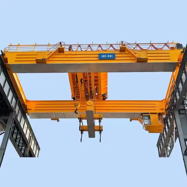
What is a Double Girder Overhead Crane with Winch Trolley?
It is a type of overhead bridge crane where the bridge structure consists of two parallel girders supported by end trucks that run on elevated runway rails. A trolley, equipped with one or two winches (hoists), travels along the top of these two girders, providing motion across the width of the bay. This design offers superior strength, higher lifting heights, and greater hook approach compared to single girder cranes.
Advantages of a Double Girder Design with a Winch Trolley
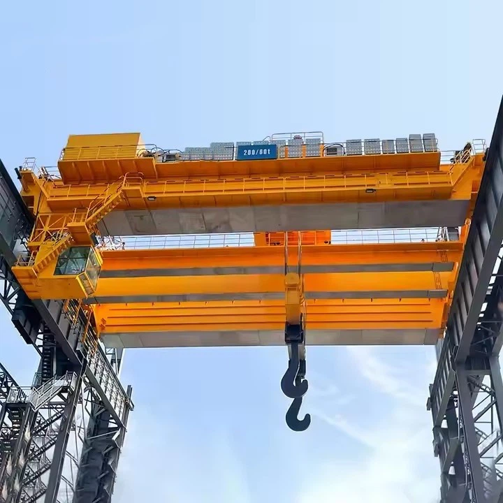
Higher Lifting Capacity: The dual-girder design distributes the load more effectively, making these cranes ideal for heavy-duty applications (typically from 10 tons up to several hundred tons).
Greater Hook Height: The winch trolley runs on top of the girders, not under them. This utilizes the full space between the girders for the hoist, providing more "lift" or "headroom" under the hook-a critical advantage in many facilities.
Superior Hook Approach: The hook can be moved closer to the runway rails because the trolley can extend over the ends of the girders, allowing for better coverage of the work area and minimizing dead space.
Durability and Long Life: Built for rigorous, frequent use in demanding environments like steel mills, fabrication shops, and paper mills.
Flexibility for Attachments: The robust structure can easily accommodate specialized below-the-hook attachments like magnets, grabs, or lifting beams.
Potential for a Main & Auxiliary Hoist: The wide trolley can often be fitted with two winches: a main hoist for full capacity and a smaller, faster auxiliary hoist for lighter loads, increasing productivity.
Comparison: Winch Trolley vs. Hoist Trolley
| Feature | Winch Trolley (Top-Running) | Hoist Trolley (Under-Hung / Standard) |
|---|---|---|
| Location | Runs on top of the bridge girders. | Suspended under a single girder. |
| Lifting Height | Maximized. Uses the space between girders. | Reduced, as the hoist hangs below the girder. |
| Capacity | Very High (Heavy-duty and severe-duty) | Low to Moderate (Light to medium-duty) |
| Cost | Higher initial cost. | More economical. |
| Ideal For | Double Girder Cranes in mills, foundries, heavy fabrication. | Single Girder Cranes or lighter double girder cranes. |
Core Components:Bearing, Gearbox, Motor, Pump
Place of Origin:Henan, China
Warranty:1 Year
Weight (KG):2000 kg
Video outgoing-inspection:Provided
Machinery Test Report:Provided
Design:Double beam
Effectiveness:high efficiency
Operating speed:High speed operation
Stability:Anti-swing function
Color:Optional
Power Source:110V/220V/230V/380V/440V,customized
Span:7.5-31.5m

Pictures & Components
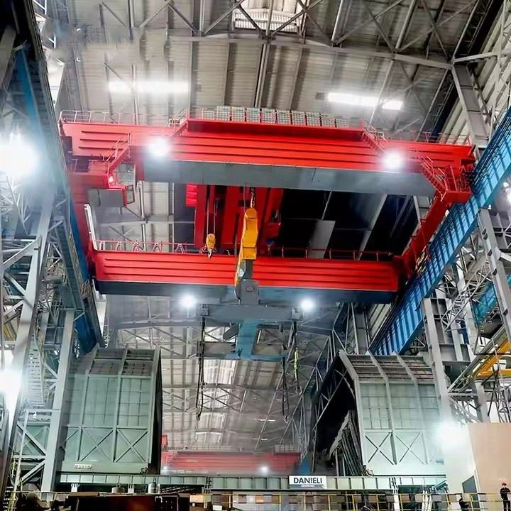
This configuration is designed for heavy-duty industrial applications where high capacity, maximum hook height, and durability are paramount.
The entire system can be divided into two main subsystems:
The Bridge: The structure that moves the entire crane along the length of the bay.
The Winch Trolley: The unit that travels across the width of the bridge and performs the lifting.
 |
 |
I. The Bridge Components
The bridge is the primary moving framework of the crane.
Bridge Girders (2):
Description: Two primary, parallel horizontal beams that span the width of the bay. They are typically fabricated box girders (for strength and rigidity) but can also be robust I-beams.
Function: To support the winch trolley, the load, and their own weight, transferring all forces to the end trucks. They have a rail mounted on top for the trolley to run on.
End Trucks (2):
Description: The structural assemblies at each end of the bridge girders.
Key Sub-Components:
Wheels: Forged steel wheels that run on the runway rails. The number of wheels per truck depends on the crane's capacity.
Axles: Shafts on which the wheels rotate.
Bearings: Mounted on the axles to allow smooth wheel rotation.
Truck Frame: The steel structure that houses the wheels and connects to the bridge girders.
 |
 |
Bridge Drive System:
Description: The system that provides motive power to move the entire bridge along the runway.
Key Sub-Components:
Bridge Drive Motors: Electric motors (often with built-in brakes) that provide power.
Reducers/Gearboxes: Connect to the motors to reduce RPM and increase torque to drive the wheels.
Couplings: Connect the motor shaft to the reducer shaft.
Brakes: Usually fail-safe, spring-set, electrically released brakes that hold the bridge stationary when power is off.
Runway System:
Description: The fixed, elevated track on which the crane operates. It is not part of the crane itself but is essential infrastructure.
Key Sub-Components:
Runway Rails: Steel rails (often similar to railroad rails) mounted on the runway beams.
Runway Beams: Heavy-duty steel beams (often wide-flange beams) that support the rails. They are supported by the building columns or freestanding columns.
Rail Clips & Bolts: Secure the rails to the runway beams.

II. The Winch Trolley Components
This is the complex unit that handles the transverse and vertical movement of the load.
Trolley Frame:
Description: A robust, rigid frame made of steel plates and shapes. It contains the side plates, cross members, and bumper stops.
Function: To house and support all other trolley components and to travel along the rails on top of the bridge girders.
The Hoist / Winch Unit: The heart of the trolley.
Description: A complete, integrated lifting device.
Key Sub-Components:
Hoist Motor: Powers the lifting and lowering functions.
Hoist Gearbox: Reduces the motor's high RPM to a usable speed for lifting heavy loads.
Drum: A steel cylinder around which the wire rope is wound and stored.
Wire Rope: High-strength, stranded steel cable that does the actual lifting.
Hook: The forged steel attachment point for the load. Swivels to prevent rope twisting.
Hoist Brake: A critical safety device, typically a disc or drum brake, that automatically engages if power is lost.
Rope Guide: Ensures the wire rope spools evenly onto the drum.

Trolley Drive System:
Description: The system that moves the trolley back and forth along the bridge girders.
Key Sub-Components:
Trolley Drive Motor(s): Provide power for movement.
Trolley Wheels: Steel wheels that run on the rails atop the bridge girders.
Trolley Reducers/Gearboxes: Provide the necessary torque for movement.
Trolley Brakes: Stop and hold the trolley in position.


III. General Crane-Wide Components
Electrical System:
Power Feed: Typically provided by festoon systems (cable and carriage) or conductor bars (enclosed busbars) that run along the runway.
Control: Operators use a pendant station (hung from the crane), an operator's cab (mounted on the bridge), or a radio remote control.
Panel Board: Contains the main disconnect, contactors, overload relays, and variable frequency drives (VFDs) for smooth control.

Safety Devices:
Limit Switches: Prevent the bridge and trolley from over-traveling and crashing into the end stops.
Load Limiters: Sensors that prevent the hoist from lifting beyond its rated capacity.
Anemometer: On outdoor cranes, measures wind speed and can disable operation if limits are exceeded.
Bumpers: Energy-absorbing buffers (rubber, polyurethane, or hydraulic) on the end trucks and trolley to absorb impact if limit switches fail.
Warning Devices: Rotating beacon lights and audible alarms to alert personnel of crane movement.

Sketch

Main technical

Advantages
1. Higher Load Capacity
Robust Structure: The dual girder design distributes the load more effectively, allowing the crane to handle extremely heavy loads, typically from 10 tons up to 500+ tons.
Heavy-Duty Trolley: The winch trolley is itself a rugged, engineered component built to handle these high capacities without deflection.
2. Greater Hook Height
Top-Running Trolley: This is the most significant advantage. Since the winch trolley runs on top of the girders, the hoist unit is positioned between the girders. This utilizes the full space between the girders for the hoist, providing maximum lift or headroom under the hook.
Ideal for Low-Clearance Buildings: Effectively adds feet of valuable lifting height compared to an under-hung system, making it essential for facilities with limited vertical space.
3. Superior Hook Approach
Extended Reach: The trolley can be designed so the hook can travel very close to the end of the runway system (the building columns). This minimizes "dead space" in the bay and allows for excellent coverage of the work area, enabling loads to be positioned with precision right next to a wall or machine.
4. Enhanced Durability and Long Service Life
Built for Severe Service: Constructed with heavy-duty plates, forgings, and high-quality components designed for rigorous, continuous use in harsh environments (e.g., foundries, mills).
Less Downtime: The robust construction leads to lower maintenance requirements and longer intervals between servicing, maximizing uptime.
5. Improved Safety and Stability
Rigid Structure: The double girder design is inherently more stable and resistant to twisting and side loads, preventing load sway and ensuring smooth, controlled operation.
Dedicated Trolley Path: The trolley runs on a dedicated rail on top of a rigid girder, offering a much more stable path than a hoist hanging from a single girder.
6. Flexibility for Specialized Applications
Main and Auxiliary Hoists: The large trolley platform can easily accommodate two hoists: a high-capacity main hoist and a smaller, faster auxiliary hoist for lighter, precision work, drastically improving productivity.
Space for Attachments: Ample space on the trolley and between the girders allows for the integration of specialized below-the-hook devices like magnets, grabs, or vacuum lifters.
7. Potential for Higher Duty Cycle
Designed for Frequent Use: Components (motors, brakes, gearboxes) are rated for more frequent starts and stops per hour (higher duty cycle), making them suitable for production environments where the crane is in constant use.
Application:
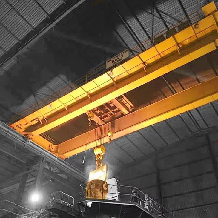
1. Steel and Metal Production
Steel Mills: Handling hot ladles, coils, slabs, and raw materials.
Foundries: Moving large molds, crucibles, and castings.
Fabrication Shops: Lifting large weldments, machined parts, and structural steel.
2. Power Generation
Hydroelectric & Thermal Plants: Installing and maintaining massive turbines, generators, rotors, and transformers.
Nuclear Facilities: Handling heavy, shielded components during maintenance and refueling.
3. Heavy Machinery and Manufacturing
Aerospace: Assembling large aircraft fuselages and wings.
Shipbuilding and Dry Docks: Moving large ship sections, engines, and propellers.
Heavy Equipment Manufacturing: Handling large frames and assemblies for mining and construction machinery.
4. Paper and Pulp Industry
Paper Mills: Installing and servicing the massive rolls and drums used in paper manufacturing machines.
5. Automotive Industry
Stamping Plants: Handling large, heavy dies for stamping body panels.
Major Assembly: Lifting large vehicle chassis and assemblies.
6. Logistics and Heavy Warehousing
Handling Heavy Unit Loads: Moving large industrial transformers, machinery, and pre-built modules.
Rail Yards and Ports: Maintenance of locomotives and heavy port machinery.
Crane production procedure
The manufacturing process of a QDY metallurgical casting bridge crane involves strict quality control and specialized engineering to ensure durability, heat resistance, and safety. Below is a step-by-step breakdown of the production procedure:
1. Design & Engineering
Load & Environment Analysis – Calculations for lifting capacity (5–500+ tons), span, and heat resistance.
CAD/3D Modeling – Structural design, stress simulations (FEA), and compliance with ISO, FEM, or GB standards.
Customization – Optional features (explosion-proofing, insulated hoists, automation) are integrated.
2. Material Selection & Preparation
Main Girders & End Carriages – High-strength steel (Q345B, Q460C) or heat-resistant alloy steel.
Wire Ropes & Hooks – Special heat-treated alloy steel (for molten metal handling).
Electrical Components – High-temperature-resistant cables, motors, and insulation materials.
3. Fabrication of Key Components
A. Bridge Girder Construction
Cutting & Welding – CNC plasma/laser cutting for precision; submerged arc welding (SAW) for high-strength joints.
Heat Treatment – Stress-relieving annealing to prevent deformation.
Machining – Drilling, milling, and surface grinding for assembly accuracy.
B. Hoist & Trolley Assembly
Hoist Drum & Gearbox – Machined for smooth operation; tested under 1.25x rated load.
Heat-Resistant Brakes – Dual-disc or electromagnetic brakes for fail-safe holding.
Ladle Hook & Safety Latch – Forged and ultrasonically tested for cracks.
C. End Trucks & Runway System
Wheel & Rail Machining – Hardened steel wheels for long wear life.
Drive Motors & Reducers – Equipped with anti-skid mechanisms for heavy loads.
4. Electrical & Control System Integration
Festoon/Conductor Bar System – For power supply along the runway.
Variable Frequency Drives (VFDs) – For smooth speed control and energy efficiency.
Safety Circuits – Overload sensors, limit switches, and emergency stop.
Operator Controls – Pendant, cabin, or remote/automated systems.
5. Surface Treatment & Corrosion Protection
Sandblasting (SA 2.5 Grade) – Removes rust and improves paint adhesion.
High-Temp Paint/Coating – Zinc-rich primer + heat-resistant topcoat (up to 800°C).
Critical Component Insulation – Ceramic fiber or refractory coatings on hooks and ropes.
6. Assembly & Testing
A. Pre-Assembly Checks
Dimensional inspection of girders, trolley, and end carriages.
Alignment of runway rails and crane tracks.
B. Load Testing (Per ISO 4310 / GB Standards)
No-Load Test – Checks motor, brake, and travel functions.
Static Load Test – 1.25x rated capacity for 10+ minutes.
Dynamic Load Test – 1.1x rated capacity with repeated movements.
Emergency Brake Test – Verifies fail-safe mechanisms.
C. Heat Resistance Validation (For Foundry Cranes)
Simulated high-temperature exposure (if required).
7. Packaging & Delivery
Disassembly (if needed) – For large cranes, components are shipped separately.
Anti-Corrosion Packaging – VCI film or desiccant for overseas transport.
Documentation – Manuals, test reports, and certifications (CE, ISO, GOST, etc.).
8. Installation & Commissioning (On-Site)
Runway alignment and crane reassembly.
Final load testing and operator training.

Workshop view:
The company has installed an intelligent equipment management platform, and has installed 310 sets (sets) of handling and welding robots. After the completion of the plan, there will be more than 500 sets (sets), and the equipment networking rate will reach 95%. 32 welding lines have been put into use, 50 are planned to be installed, and the automation rate of the entire product line has reached 85%.


Hot Tags: double girder overhead crane with winch trolley, China double girder overhead crane with winch trolley manufacturers, suppliers, factory, Double Girder Overhead Travelling Crane, Double Girder Overhead Crane
You Might Also Like


Send Inquiry