


Cranes Box Double Beam Overhead Crane For Foundry
Products Description
What is a Box Double Beam Overhead Crane?
It is an overhead crane where the main bridge consists of two box-shaped girders made of welded steel plates. This double girder bridge travels on end trucks along runway beams, and a hoist trolley moves along the top of the two box girders. This design is renowned for its superior strength and rigidity.
Key Advantages for Foundry Applications
Foundries present harsh conditions, including heat, dust, abrasion, and heavy loads. The box double beam crane is specifically suited for this:
1. Exceptional Strength & Rigidity
Heavy Load Capacity: The box girder design offers immense structural integrity, capable of handling the extreme weights commonly found in foundries, such as large ladles of molten metal, heavy castings, and molds.
Minimal Deflection: The design significantly reduces beam deflection (sagging) under load, which is crucial for precision positioning and overall stability, especially when handling valuable molten metal.
2. Superior Hook Height
The trolley runs on top of the girders, not underneath them. This design maximizes the lift height under the hook, which is essential for lifting loads out of deep pits, clearing furnace walls, and handling tall equipment like ladles and molds.
3. Built for Harsh Environments
Heat Resistance: Critical components can be specified with heat shielding to protect them from radiant heat from molten metal. Motors and electrical equipment are often rated for high ambient temperatures (e.g., Class F or H insulation).
Dust and Debris Protection: Electrical panels are typically housed in sealed, insulated, and sometimes air-conditioned cabins to protect sensitive components (PLCs, VFDs) from conductive foundry dust and fumes.
Robust Construction: All components are built to severe-duty service standards (like FEM 9m or Class F) to withstand shock loads, abrasion, and continuous use.
4. Enhanced Safety & Reliability
Stable Platform: The rigid double girder structure provides a stable base for the trolley, preventing sway and ensuring precise load control.
Redundancy Options: For the most critical applications like molten metal handling (ladle cranes), this design can accommodate dual hoists (main and auxiliary) and fail-safe braking systems, which are mandatory for safety.
5. Precision Control
The rigid structure provides an ideal platform for Variable Frequency Drives (VFDs) on all motions (hoist, trolley, bridge). VFDs allow for smooth, creep-speed precision, which is vital for pouring molten metal without splashing and for positioning heavy castings accurately.
Core Components:Bearing, Gearbox, Motor, Pump
Place of Origin:Henan, China
Warranty:1 Year
Weight (KG):2000 kg
Video outgoing-inspection:Provided
Machinery Test Report:Provided
Design:Double beam
Effectiveness:high efficiency
Operating speed:High speed operation
Stability:Anti-swing function
Color:Optional
Power Source:110V/220V/230V/380V/440V,customized
Span:7.5-31.5m

Pictures & Components
1. Bridge Structure
The main framework that spans the bay and travels on runway beams.
Double Box Girders: The core of the crane. These are massive, welded box-section beams made from high-tensile steel plates. They provide superior strength, rigidity, and minimal deflection under the extreme loads of foundry applications (e.g., heavy castings, molten metal ladles).
 |
 |
End Trucks: Located at each end of the bridge, they house the bridge wheels, bearings, axles, and drive motors. Built with heavy-duty, machined components for perfect alignment and smooth travel under severe loads.
Drive Mechanism: Consists of VFD-controlled motors, fail-safe brakes, and heavy-duty gearboxes that propel the entire crane along the runway tracks. Gearing is designed for slow, controlled movement.
Walkways & Platforms: Full-length, enclosed walkways with high-friction grating provide safe access for maintenance. Crucially, they often include heat shielding on their underside.
 |
 |
2. Trolley (Crab)
The unit that travels across the top of the box girders and carries the hoisting machinery.
Trolley Frame: A heavily welded, rigid steel frame designed to support the immense weight of the hoist(s) and the load.
Trolley Drive System: Includes VFD-controlled motors, fail-safe brakes, and gearboxes that drive the trolley wheels along rails on top of the bridge girders.
Heat Protection System: A critical feature. The entire trolley underside is protected by removable heat shield plates (often stainless steel) to deflect radiant heat from molten metal away from vital mechanical and electrical components above.

3. Hoisting Unit
The system responsible for lifting and lowering the load. Configurations vary by application.
Hoist Motor: High-capacity motor with a high insulation class (e.g., Class H - 180°C) to withstand intense ambient heat.
Hoist Gearbox: A heavy-duty, precision-manufactured gearbox built for high shock loads and continuous duty.
Drum: A large-diameter drum designed with specific grooving to properly spool multiple layers of wire rope.
Wire Rope: Specialized, high-grade non-rotating wire ropes resistant to heat and abrasion. They are oversized for an extra factor of safety.
For Foundries: For ladle handling, a dual-hoist system (Main + independent Auxiliary safety hoist) is mandatory.

4. Load Handling Components
Hook: For general foundry work, a forged alloy steel hook with a high safety factor is used. For molten metal, a special ladle hook designed to engage the ladle's bail pins is required, often with an anti-rotation device.
Sheaves & Blocks: Large-diameter sheaves made from high-tensile steel with machined grooves to reduce rope wear.


5. Electrical and Control Systems
Insulated Electrical Cabin: The most crucial electrical feature. All sensitive components (PLCs, VFDs, contactors) are housed in a sealed, insulated, and air-conditioned cabin mounted on the crane bridge. This protects them from extreme heat, conductive dust, and moisture.
Variable Frequency Drives (VFDs): Installed on all motions (Hoist, Trolley, Bridge). VFDs provide incredibly smooth acceleration and deceleration to prevent load swing and, critically, molten metal sloshing.
PLC Control: A Programmable Logic Controller provides advanced control, diagnostics, and safety interlocking.
Operator Control: Either an air-conditioned, pressurized operator's cab with tinted glass or an advanced remote control system allows the operator to work from a safe, optimal location.

6. Safety Devices
Overload Limit Switch: Prevents the crane from lifting a load beyond its rated capacity.
Upper/Lower Limit Switches: Prevents hook over-travel.
Fail-Safe Braking: Spring-set, power-released brakes on all motions that engage automatically upon power loss.
Anemometer: For outdoor cranes, measures wind speed that could affect a suspended load.
Anti-Collision Systems: Prevents collisions with other cranes in the same bay.

Sketch

Main technical

Advantages
1. Exceptional Strength & Load Capacity
Robust Construction: The box girder design, made from welded steel plates, provides immense structural integrity and rigidity. This allows it to handle the extreme weights common in foundries, such as large ladles of molten metal, heavy sand molds, and finished castings, with minimal deflection (sagging).
Handles Shock Loads: The robust design effectively absorbs the dynamic shock loads that occur when lifting a ladle that may have slag or solidified metal attached.
2. Superior Hook Height & Clearance
Top-Running Trolley: The trolley runs on rails on top of the two girders. This design maximizes the available hook height-the distance from the floor to the hook. This is critical for lifting loads out of deep furnace pits, clearing furnace walls, and handling tall equipment like ladles and molds.
3. Unmatched Durability in Harsh Conditions
Heat Resistance: Critical components can be outfitted with heat shield plates (often stainless steel) on the underside of the girders and trolley to deflect radiant heat from molten metal. Motors and electrical components are rated for high ambient temperatures.
Dust and Debris Protection: The enclosed box girder design itself is less susceptible to internal dust accumulation compared to open truss girders. Furthermore, electrical panels are housed in sealed, insulated, and air-conditioned cabins to protect sensitive PLCs and VFDs from conductive foundry dust and fumes, which is a primary cause of electrical failure.
Corrosion Resistance: The crane is often built with special paints or coatings to resist corrosion from the humid, fume-laden foundry atmosphere.
4. Enhanced Safety Features
Stable Platform: The rigid double girder structure provides a wide, stable base for the trolley, preventing tipping and ensuring precise, controlled load movement-a non-negotiable requirement when moving molten metal.
Redundancy for Critical Tasks: For molten metal handling (ladle cranes), this design can accommodate dual hoists (main and auxiliary) and fail-safe braking systems. If the main hoist fails, the auxiliary hoist prevents a catastrophic drop.
Precision Control: The stable structure is ideal for Variable Frequency Drives (VFDs) on all motions. VFDs allow for smooth, jerk-free acceleration and deceleration and a micro-speed function, which is vital for preventing molten metal slosh and for precise positioning of heavy casts.
5. Versatility and Efficiency
Adaptable Configurations: It can be fitted with various hook attachments, magnets, or grabs for handling different materials (scrap, molds, finished products).
Improved Productivity: By enabling safe and efficient movement of heavy materials through every stage of the foundry process, it significantly boosts overall productivity and reduces manual handling risks.
Application:
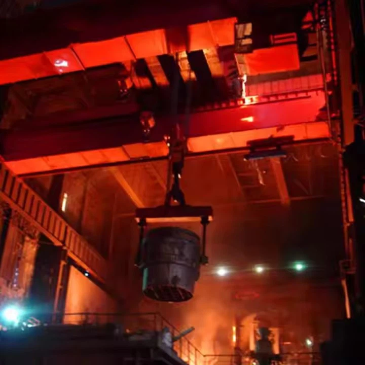
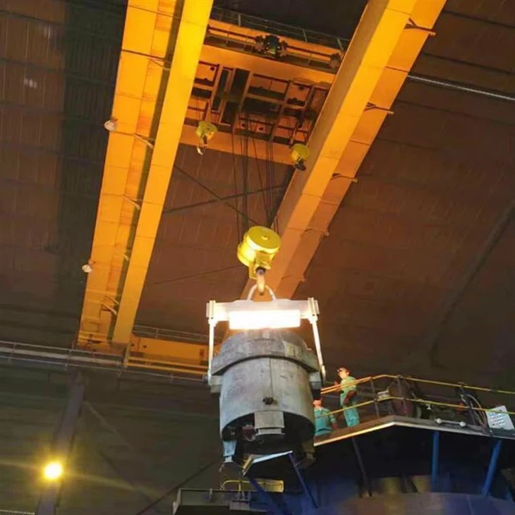
1. Molten Metal Handling (Ladle Crane)
This is the most critical application. The crane is used to transport ladles filled with molten metal from the melting furnace (e.g., induction furnace, arc furnace) to the pouring area.
Example: Pouring molten iron or aluminum into sand molds or a holding furnace with precise control to avoid splashing.
2. Furnace Charging
Using a magnet or grapple attachment on the hoist to load raw materials (scrap metal, pig iron, alloys) into the melting furnace.
3. Mold Handling
Moving large, heavy sand molds through the production line-from the molding station, to the pouring area, and finally to the shakeout station where the casting is removed.
4. Casting Removal and Finishing
Lifting finished castings from molds after shakeout and transferring them to areas for cleaning, grinding, heat treatment, or shipping.
5. Slag and Debris Handling
Moving slag pots or handling waste materials from the production process.
6. Maintenance and Repair
Lifting and moving heavy furnace components, lids, or machinery for repair and maintenance, which is crucial for minimizing downtime.
Crane production procedure
The manufacturing process of a QDY metallurgical casting bridge crane involves strict quality control and specialized engineering to ensure durability, heat resistance, and safety. Below is a step-by-step breakdown of the production procedure:
1. Design & Engineering
Load & Environment Analysis – Calculations for lifting capacity (5–500+ tons), span, and heat resistance.
CAD/3D Modeling – Structural design, stress simulations (FEA), and compliance with ISO, FEM, or GB standards.
Customization – Optional features (explosion-proofing, insulated hoists, automation) are integrated.
2. Material Selection & Preparation
Main Girders & End Carriages – High-strength steel (Q345B, Q460C) or heat-resistant alloy steel.
Wire Ropes & Hooks – Special heat-treated alloy steel (for molten metal handling).
Electrical Components – High-temperature-resistant cables, motors, and insulation materials.
3. Fabrication of Key Components
A. Bridge Girder Construction
Cutting & Welding – CNC plasma/laser cutting for precision; submerged arc welding (SAW) for high-strength joints.
Heat Treatment – Stress-relieving annealing to prevent deformation.
Machining – Drilling, milling, and surface grinding for assembly accuracy.
B. Hoist & Trolley Assembly
Hoist Drum & Gearbox – Machined for smooth operation; tested under 1.25x rated load.
Heat-Resistant Brakes – Dual-disc or electromagnetic brakes for fail-safe holding.
Ladle Hook & Safety Latch – Forged and ultrasonically tested for cracks.
C. End Trucks & Runway System
Wheel & Rail Machining – Hardened steel wheels for long wear life.
Drive Motors & Reducers – Equipped with anti-skid mechanisms for heavy loads.
4. Electrical & Control System Integration
Festoon/Conductor Bar System – For power supply along the runway.
Variable Frequency Drives (VFDs) – For smooth speed control and energy efficiency.
Safety Circuits – Overload sensors, limit switches, and emergency stop.
Operator Controls – Pendant, cabin, or remote/automated systems.
5. Surface Treatment & Corrosion Protection
Sandblasting (SA 2.5 Grade) – Removes rust and improves paint adhesion.
High-Temp Paint/Coating – Zinc-rich primer + heat-resistant topcoat (up to 800°C).
Critical Component Insulation – Ceramic fiber or refractory coatings on hooks and ropes.
6. Assembly & Testing
A. Pre-Assembly Checks
Dimensional inspection of girders, trolley, and end carriages.
Alignment of runway rails and crane tracks.
B. Load Testing (Per ISO 4310 / GB Standards)
No-Load Test – Checks motor, brake, and travel functions.
Static Load Test – 1.25x rated capacity for 10+ minutes.
Dynamic Load Test – 1.1x rated capacity with repeated movements.
Emergency Brake Test – Verifies fail-safe mechanisms.
C. Heat Resistance Validation (For Foundry Cranes)
Simulated high-temperature exposure (if required).
7. Packaging & Delivery
Disassembly (if needed) – For large cranes, components are shipped separately.
Anti-Corrosion Packaging – VCI film or desiccant for overseas transport.
Documentation – Manuals, test reports, and certifications (CE, ISO, GOST, etc.).
8. Installation & Commissioning (On-Site)
Runway alignment and crane reassembly.
Final load testing and operator training.

Workshop view:
The company has installed an intelligent equipment management platform, and has installed 310 sets (sets) of handling and welding robots. After the completion of the plan, there will be more than 500 sets (sets), and the equipment networking rate will reach 95%. 32 welding lines have been put into use, 50 are planned to be installed, and the automation rate of the entire product line has reached 85%.


Hot Tags: cranes box double beam overhead crane for foundry, China cranes box double beam overhead crane for foundry manufacturers, suppliers, factory, Double Girder Overhead Travelling Crane, Double Girder Overhead Crane
You Might Also Like


Send Inquiry