


20 Ton EuropeanSingle Overhead Bridge Crane
Products Description
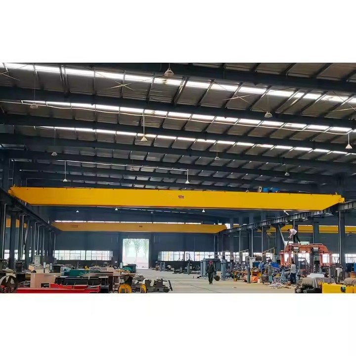
The 20 Ton European Single Girder Overhead Bridge Crane represents a paradigm shift from traditional heavy-duty lifting equipment. Originating from European design standards (FEM, DIN, ISO), this crane utilizes advanced modular concepts and high-strength steel to deliver a solution that is lighter, more energy-efficient, and offers better space utilization than conventional cranes
Lifting Capacity 1 – 20 tons (custom up to 50+ tons)
Span 5 – 30 meters
Lifting Height 3 – 30 meters
Lifting Speed 1 – 20 m/min (adjustable)
Trolley Speed 5 – 30 m/min
Crane Travel Speed 10 – 60 m/min
Power Supply 380V/415V, 50Hz (3-phase)
Duty Class FEM A3-A5 (Medium to Heavy Duty)

Pictures & Components
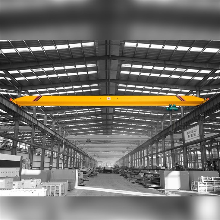
1. Main Girder: The Primary Load-Bearing Structure
The main girder is the central horizontal beam spanning the workshop width, supporting the hoist and the lifted load.
Structural Design
Box Girder Design: Unlike traditional I-beams, European cranes utilize an optimized partial rail box girder (box-type structure). This provides superior bending resistance and torsional rigidity.
Material: Typically fabricated from Q355B or Q345B high-strength structural steel.
Manufacturing Process
The quality of the main girder is ensured through a rigorous process chain:
CNC Plasma Cutting: Ensures dimensional precision of the web plates.
Robot CO₂ Welding: Automated submerged arc welding (SAW) is used for main welds.
Shot Blasting: Complete girder is shot-blasted to Sa2.5 standard for surface preparation and stress relief.
Painting: Epoxy zinc-rich primer applied (≥80–120μm thickness) for corrosion resistance.
Performance Indicators
Deflection Control: Under full load (20 tons), deflection is strictly limited to ≤ L/1000 (e.g., for an 18m span, deflection ≤ 18mm).
Lower Flange Track: The lower flange plate of the box girder is specifically machined to serve as the running track for the electric hoist.

2. End Carriages & Bridge Travel Mechanism
The end carriages are mounted at each end of the main girder. They house the wheels and travel drives that move the entire crane along the runway rails.
End Carriage Structure
Fabrication: Made from welded rectangular steel tubes or folded steel plates using Q235B/Q355B material.
Connection: Connected to the main girder using Class 10.9 high-strength bolts and precision locating pins (tolerance ±1mm) for structural integrity and easy transport.
Buffer & Safety: Equipped with rubber or polyurethane buffers and anti-derailing end plates at both ends.
 |
 |
Crane Travel Drive (Three-in-One Mechanism)
The bridge travel uses a "three-in-one" drive unit where the motor, gearbox, and brake are integrated into a single compact assembly.
Motor: Squirrel-cage three-phase motor, Class F insulation, IP55 protection.
Reducer: Hard tooth surface reducer (gears hardened to HRC60) for high transmission efficiency (≥95%) and low noise.
Brake: Self-adjusting electromagnetic disc brake for reliable stopping.
Speed Control: Variable Frequency Drive (VFD) for stepless speed regulation, typically ranging from 3–30 m/min.
 |
 |
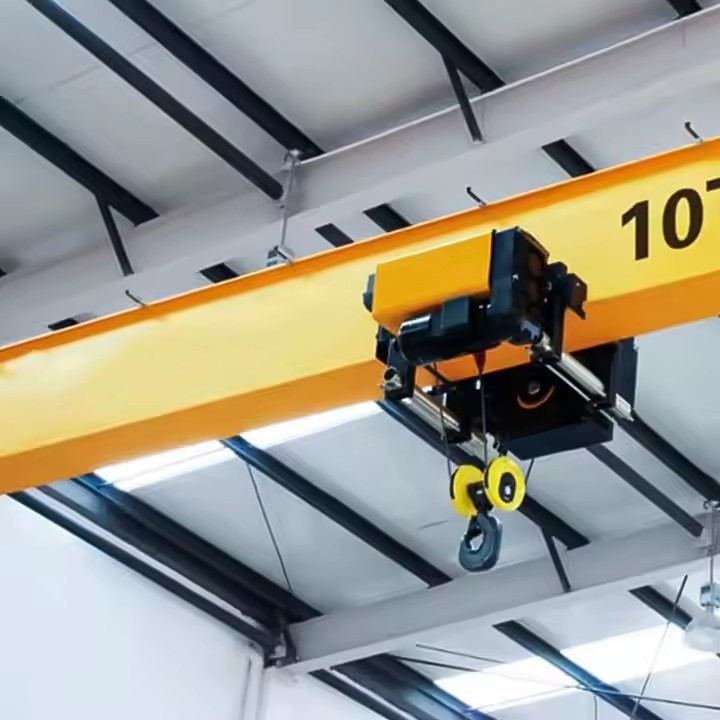
3. Lifting Mechanism (Electric Hoist)
The electric hoist is the core component responsible for lifting and lowering the 20-ton load. It travels along the lower flange of the main girder.
Hoist Configuration
Compact Design: Parallel arrangement of motor and drum (C-type structure) minimizes dead weight and headroom.
Lifting Speed: Typically 5 m/min (main speed) / 0.8 m/min (creep speed) for precise positioning.

4. Power Supply & Electrical Systems
This system distributes power and controls the crane's movements. European designs standardize on high-ingress protection ratings.
Power Supply Methods
Conductor Bar (Busbar) System: Enclosed IP54-rated copper or aluminum bars mounted along the runway and main girder.
Festoon Cable System: Flat cables running on sliding trolleys, ideal for lower amperage or complex environments.
Control System
Core Technology: Programmable Logic Controller (PLC) + Variable Frequency Drive (VFD) + Contactor coordination.
VFD Benefits: Provides "stepless" speed control, anti-sway functionality (minimal starting impulse <0.3g), and energy savings.
Control Modes:
Pendant Control: Low-voltage (24V) push-button station, standard for ground operation.
Radio Remote Control: Wireless operation with up to 100m range, allowing the operator to choose the safest viewing position.
Cab Control: Optional heated/air-conditioned cabin for high-frequency or high-altitude operation.

Safety & Monitoring Features
Overload Protection: Cut-off at 105% of rated load (21 tons).
Limit Switches: Dual-stage lifting height limiters, plus travel end limiters.
Audible/Visual Alarms: Standard for zone warning.

.
5. Trolley Travel Mechanism
While integrated with the hoist in single-girder designs, the trolley specifically moves the hoist across the main girder.
Structure & Drive
Side-Hanging Design: The trolley hangs from the lower flange of the main girder, utilizing a side-hanging structure to minimize the building's headroom requirement.
Wheels: Forged steel wheels, heat-treated to a tread hardness of HRC55–60 for wear resistance.
Drive: Independent motor (typically 0.75–1.5kW for 20T models) with VFD, achieving speeds of 2–20 m/min.


Sketch

Main technical

Advantages
1. Structural & Spatial Advantages (Low Headroom Design)
This is the most significant engineering advantage. European cranes are designed to maximize your building's usable space.
Lower Hook Height: By integrating the hoist with the box girder and reducing the profile of the end carriages, the overall crane height is reduced. For a given building height, a European crane provides 200-500mm more lifting height than a traditional I-beam crane. (This often saves a new building one full row of bricks/masonry).
Reduced Dead Weight: The optimized box girder and compact hoist result in a crane that is 30-40% lighter than traditional designs (e.g., a 20T European crane weighs ~6-8 tons vs. ~10-12 tons for a traditional model).
Lower Wheel Load: A lighter crane imposes less force on the runway beams and building columns.
Workshop benefit: You can often use smaller, cheaper runway rails (e.g., P24 instead of P38) and lighter supporting steel structures.
Smaller Hook Approach: The compact hoist can get closer to the end carriages.
Result: The crane can lift loads within 100-200mm of the factory wall, capturing more usable floor area (typically gaining 0.5-1m of coverage per bay).
2. Operational & Performance Advantages
Variable Frequency Drive (VFD) Standard: Unlike traditional cranes with two-speed motors (causing jerky starts/stops), European cranes use VFDs as standard.
Anti-Sway: Smooth acceleration (up to 40 seconds ramp-up time) keeps the 20-ton load steady, preventing dangerous pendulum swings.
Creep Speed: VFD provides micro-speed (e.g., 0.8 m/min) for precise positioning of heavy dies or machinery.
Lower Noise Operation: VFDs eliminate the mechanical impact of contactors and gear shifting. European cranes operate at ≤75dB, significantly quieter than traditional cranes (≈85-90dB).
Higher Duty Cycle Capability: The robust gearbox and motor are rated for 40-60% ED (Electric Duty) vs. 25% ED on cheaper cranes. This means it can run hotter and longer without tripping thermal overloads.
3. Economic & Energy Advantages
Energy Savings (20-30%): The lighter structure has less rolling resistance. VFDs regenerate braking energy and avoid high starting currents. This directly lowers your electricity bill.
Reduced Infrastructure Costs: Because the wheel load is lower, the required runway beams and crane rails are smaller and cheaper. The workshop columns do not need to be as heavily reinforced.
Lower Shipping & Installation Cost: A 30% lighter crane means smaller trucks, easier on-site assembly, and no need for a massive mobile crane to place the girders.
Less Maintenance: Modular components (plug-and-play hoist) and self-adjusting brakes reduce downtime. Lubrication intervals are longer (gear oil lasts 10,000+ hours).
4. Safety Advantages
Secondary (Emergency) Brake: European standards (FEM/ISO) often mandate a separate mechanical brake on the drum, independent of the motor brake. If the primary brake fails, this safety brake catches the load automatically.
Better Overload Protection: Strain gauge load cells are integrated into the rope anchor or hook block, providing analog weight reading (not just a binary cut-off). The operator sees the exact weight on a display.
Smoother Travel = Less Load Sway: A swaying 20-ton load is a deadly projectile. VFD-controlled anti-sway algorithms drastically reduce this risk.
5. Maintenance & Lifespan Advantages
IP55 Protection (Standard): Motors and electronics are sealed against dust and water. Traditional cranes often use IP44, which allows conductive dust to enter and short-circuit controls.
Class F Insulation (Standard): Handles higher temperatures (155°C) vs Class B (130°C) on cheap cranes. This extends motor life in hot foundry or forging environments.
Quick-Change Components: The "3-in-1" drive unit (motor+brake+gearbox) can be swapped in 30 minutes. Traditional separate components take hours to align and replace.
Application:
| Machinery Manufacturing | Assembling heavy equipment (e.g., presses, turbines), moving large components between production lines, handling raw steel plates and finished parts . |
| Warehousing & Logistics | Loading/unloading steel coils, heavy pallets, or containers; serving automated three-dimensional warehouses; managing large inventory in material yards . |
| Energy & Heavy Industry | Handling pipes, large storage tanks, and petrochemical equipment; maintenance of heavy parts in power plants (limited to ambient temperatures -20°C to 40°C) . |
| Building Materials & Construction | Lifting prefabricated concrete elements, steel structures, wood, and paper rolls . |
| Automotive & Assembly | Handling large stamping dies and performing precision assembly of large automotive or aviation parts where smooth, anti-sway control is critical . |
| Specialized Environments | Available with specific modifications for cold chain logistics, clean rooms (dust-free lubrication), or nuclear power facilities (e.g., stainless steel components) |
Crane production procedure
🏗️ Crane Production Procedure
The manufacturing of a 10 Ton Single Girder Overhead Bridge Crane follows strict quality control standards to ensure safety, durability, and performance.
Phase 1: Design & Engineering
The process begins with a custom engineering approach tailored to the customer's specific workshop conditions.
Key activities include:
Requirement Analysis: Engineers work closely with the customer to determine critical parameters-lifting capacity (20 tons), span length, lifting height, duty cycle (FEM/ISO class), and environmental conditions (temperature, humidity, corrosion risk).
Structural Calculation: Using FEM (European Design Standards), the main girder, end carriages, and wheel loads are calculated to ensure deflection is controlled to ≤ L/1000.
Modular Design: European cranes utilize modular components (hoist, drives, electrical panels), allowing for faster assembly and easier future maintenance.
🔧 2. Raw Material Preparation
Select high-quality steel (e.g., Q235 / Q345)
Inspect materials for:
Thickness
Surface defects
Mechanical properties
👉 Only approved materials proceed to fabrication
Phase 3: Metal Structure Fabrication (Main Girder & End Carriages)
This is the most critical phase for structural integrity. The European box girder design demands high precision to prevent distortion.
3.1 Surface Pretreatment
Steel plates are processed through a roller-way conveyor blasting machine to remove rust and mill scale, achieving Sa2.5 surface cleanliness (near-white metal).
A primer coat (epoxy zinc-rich, ≥80μm) is applied immediately to prevent flash rusting.
3.2 Cutting & Marking
Plates are cut using CNC plasma cutting or semi-automatic cutting machines for dimensional accuracy.
Web plates, cover plates, and stiffener plates are cut to specified dimensions.
3.3 Welding (Main Girder)
The main girder uses a bias-rail box structure to optimize strength-to-weight ratio.
Welding Platform: Assembly occurs on a dedicated U-shaped welding fixture that prevents distortion during welding.
Welding Process:
Tack welding first positions components.
Robot CO₂ welding or automatic submerged arc welding (SAW) is used for main longitudinal seams.
Anti-Distortion Technique: A specific welding sequence is employed (alternating between ends and sides) to cancel out heat-induced distortion.
Deflection Control: The design ensures vertical deflection under full load remains ≤ L/1000 (e.g., for an 18m span, ≤18mm).
3.4 End Carriage Fabrication
End carriages are fabricated from rectangular steel tubes or folded steel plates (Q355B material).
After welding, the end carriage undergoes one-time positioning machining on a CNC machine to ensure precise wheel bore alignment and fit tolerances.
Each end carriage is equipped with double-rim wheels, buffers, and anti-derailing protection devices.
3.5 Flaw Detection (Non-Destructive Testing)
Ultrasonic Testing (UT) or radiographic (X-ray) testing is applied to 100% of critical butt weld seams.
This detects internal flaws (porosity, cracks, incomplete penetration) that could compromise structural safety.
3.6 Stress Relief
Vibratory stress relief is applied to the welded structure to remove residual stresses from welding, preventing dimensional changes over time.
🔍 4. Welding Inspection
Non-destructive testing (NDT):
Ultrasonic testing (UT)
Magnetic particle testing (MT)
👉 Detects internal and surface defects
⚙️ 5. Machining Process
Precision machining of:
Wheel sets
Bearing housings
End carriages
👉 Guarantees alignment and smooth operation
🧩 6. Component Assembly
Install:
End carriages
Electric hoist
Trolley mechanism
Drive systems
👉 Mechanical parts are aligned and secured
⚡ 7. Electrical System Installation
Install:
Control panels
Motors and wiring
Limit switches and safety devices
👉 Includes grounding and insulation checks
🎨 8. Surface Treatment & Painting
Shot blasting (rust removal)
Primer coating
Final paint finish (custom color available)
👉 Improves corrosion resistance and appearance
🧪 9. Testing & Quality Inspection
No-load Test
Check operation without load
Load Test
Static test: 125% rated load
Dynamic test: 110% rated load
Functional Testing
Hoisting, traveling, braking, and control systems
👉 Ensures compliance with safety standards
📦 10. Packaging & Delivery
Disassemble into transportable parts
Secure packaging for:
Girder
Hoist
Electrical components
👉 Delivered by container or bulk shipment
📋 11. Installation & Commissioning (Optional)
On-site installation guidance
Rail alignment and system setup
Final operational testing

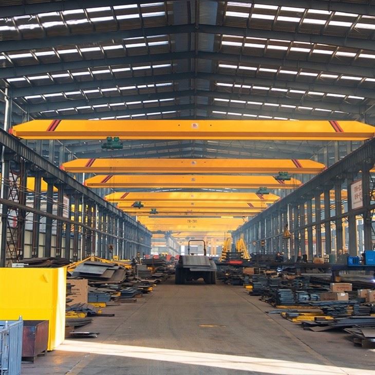
Workshop view:
The company has installed an intelligent equipment management platform, and has installed 310 sets (sets) of handling and welding robots. After the completion of the plan, there will be more than 500 sets (sets), and the equipment networking rate will reach 95%. 32 welding lines have been put into use, 50 are planned to be installed, and the automation rate of the entire product line has reached 85%.


Hot Tags: 20 ton europeansingle overhead bridge crane, China 20 ton europeansingle overhead bridge crane manufacturers, suppliers, factory
You Might Also Like


Send Inquiry