









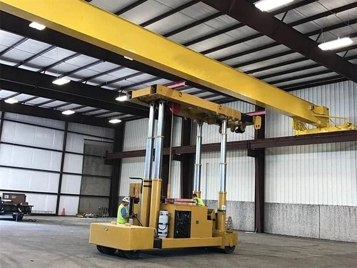
Single Girder Bridge Crane Hot Sale
Products Description
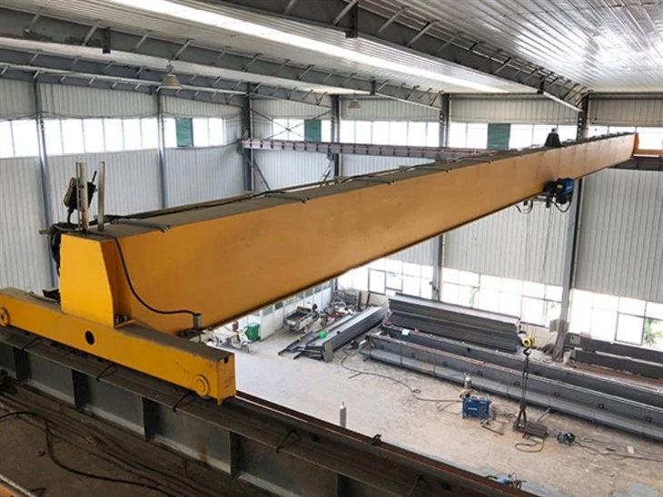
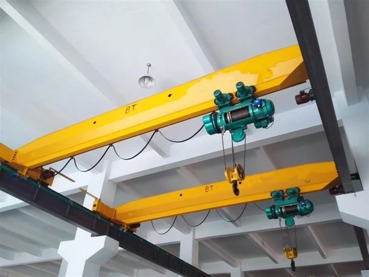
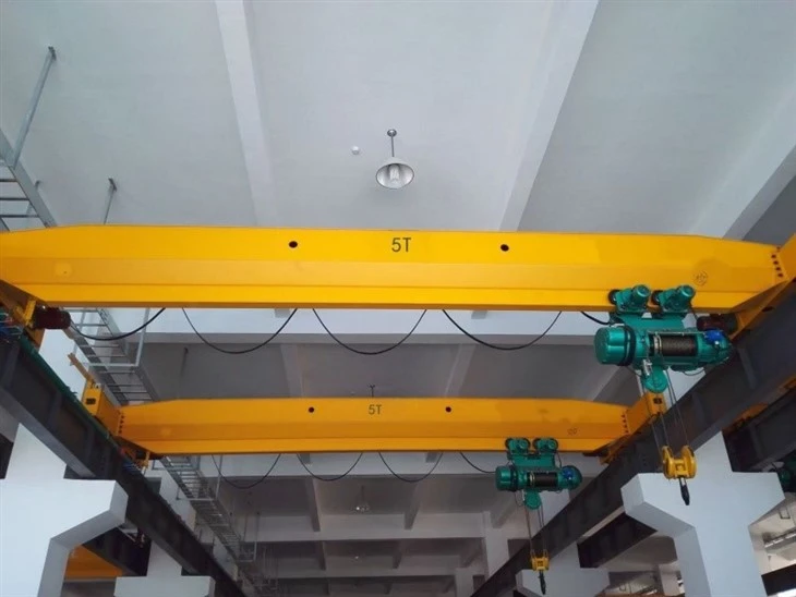
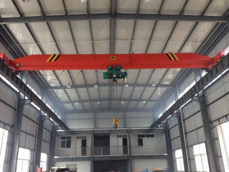
A single girder bridge crane (also known as an under-running bridge crane) is a type of overhead lifting system where the hoist and trolley run on the bottom flange of a single, primary beam (the bridge girder). This entire bridge girder is supported and moves along two runways, which are typically mounted to the building's roof structure or support columns.
Core Components: Gearbox, Motor, Gear
Place of Origin: Henan, China
Warranty: 1 Year
Weight (KG): 10000 kg
Video outgoing-inspection: Provided
Machinery Test Report: Provided
Selling Units: Single item
Single package size: 600X300X300 cm
Single gross weight: 200.000 kg
Pictures & Components
1.Main beam
The main beam has three critical jobs:
Support the Load: It must carry the weight of the hoist, trolley, and the lifted load without failing.
Resist Bending (Deflection): It must be stiff enough to minimize sagging when loaded, ensuring stability and precise load positioning.
Provide a Runway: Its bottom flange acts as the runway rail for the hoist trolley.
2.Lifting System
How the Lifting System Works Together
The integration of these components creates a cohesive system:
Mounting: The hoist is suspended from, or seated on, the trolley frame.
Movement: The trolley wheels run along the bottom flange of the main bridge girder.
Operation:
The operator uses the control (pendant or remote) to send commands.
For lifting/lowering, power is sent to the hoist motor.
For cross travel, power is sent to the trolley motor (if motorized).
This allows the operator to position the hook anywhere within the crane's working area by combining the crane's long travel, the trolley's cross travel, and the hoist's vertical lift.
 |
 |
3.End carriage
Frame: The rigid steel structure that houses all other components. It is bolted or connected to the main girder.
Wheels (Tracks): The wheels that run on the runway beam's flange. There are typically two wheels per end carriage (four total for the crane).
Axles & Bearings: The axles support the wheels, and high-quality bearings ensure smooth rotation with minimal friction.
Drive Unit (on driven end): On a motorized crane, one end carriage will contain an electric motor, gearbox, and brake that power the wheels to move the entire crane.
Collector System (if electrified): The point where electrical power is picked up from the runway conductors (busbars or festoon system) to supply the crane and hoist.
 |
 |
4.Crane travelling mechanism
Traction: The drive wheels must have enough friction with the runway beam to propel the crane without slipping, especially when starting or stopping.
Alignment: The entire mechanism depends on the runway beams being parallel and level. Misalignment causes binding, excessive wear, and increased power consumption.
Duty Cycle: The drive motor and brake are rated for a specific duty cycle (e.g., CMAA Class A through F). Using a light-duty mechanism in a severe-duty application will lead to rapid failure.
5.Trolley travelling mechanism
Trolley Frame: The rigid steel structure that holds all components and serves as the interface for the hoist.
Drive Motor: A compact electric gearmotor, sized to move the combined weight of the trolley, hoist, and load along the girder's bottom flange.
Brake: Often an integral part of the gearmotor, this is a fail-safe brake that holds the trolley in position when not powered, preventing unintended movement.
Gearbox: Reduces the motor's high RPM to a usable output speed and increased torque for the drive wheels.
Wheels (Trolley Tracks): Typically four wheels (two per side) that run on the bottom flange of the main girder. The wheels are mounted to the trolley frame with axles and bearings.
Drive Shaft & Couplings: Connects the gearbox output to the drive wheels.
6.Crane wheel
Tread: The surface of the wheel that rolls on the top of the runway beam flange. It bears the vertical load.
Flange: The raised rim on the inside of the wheel. It is a critical safety feature that guides the wheel along the runway beam and prevents derailment.
Hub & Bore: The central part of the wheel that houses the bearing and connects to the axle.

7.Crane Hook
Shank (Bail): The top, straight portion that connects to the hoist's hook block or swivel.
Saddle (Belly): The curved, load-bearing inner surface of the hook. This is where the load sling or chain rests.
Throat (Opening): The gap between the tip of the hook and the shank. The size of the throat determines what can be lifted.
Tip (Point): The end of the hook.
Safety Latch: A spring-loaded latch that closes the throat of the hook to prevent slings or chains from accidentally slipping off ("unreeving").

8.Motor
Shank (Bail): The top, straight portion that connects to the hoist's hook block or swivel.
Saddle (Belly): The curved, load-bearing inner surface of the hook. This is where the load sling or chain rests.
Throat (Opening): The gap between the tip of the hook and the shank. The size of the throat determines what can be lifted.
Tip (Point): The end of the hook.
Safety Latch: A spring-loaded latch that closes the throat of the hook to prevent slings or chains from accidentally slipping off ("unreeving").

.
9.Sound and light alarm system & limit switch
Sound and Light Alarm System
This is the crane's primary warning system, designed to alert personnel in the area before and during crane movement.
Purpose & Function:
To provide a clear, unambiguous warning that the crane is about to move or is in motion.
To increase situational awareness, preventing accidents and ensuring personnel safety.
Limit Switches
Limit switches are safety devices that automatically halt the movement of the crane in a specific direction to prevent it from traveling beyond its intended safe limits. They are essentially "stop" buttons that are triggered by the machine itself.

10.Safety Devices
A single girder bridge crane employs a defense-in-depth strategy:
Prevention: Devices like the Overload Limiter and Sound/Light Alarm prevent a hazardous situation from starting.
Automatic Intervention: Limit Switches and Motor Brakes automatically act to stop a hazard if operational limits are exceeded.
Emergency Action: The E-Stop allows for immediate human intervention in an emergency.
Containment & Mitigation: Buffers and hooks with latches provide physical protection to minimize the consequences of an incident.
11.Control Mode
Pendant Control (Push-Button Station)
This is the most common and standard control mode for single girder cranes.
Radio Remote Control
This is a wireless system that offers the operator freedom of movement.
Cabin Control (Operator Cab)
This is less common for single girder cranes and is typically reserved for very heavy-duty or intensive-use double girder cranes.
Manual / Geared Operation (No Motorized Control)
This is a non-powered control mode for the crane and trolley travel.

Sketch

Main technical

Advantages
1. Lower Initial Cost and Investment
This is often the most significant advantage.
Less Material: Requires only one main bridge girder instead of two.
Simpler Components: End trucks, trolleys, and hoists are generally less complex and expensive than those for double girder cranes.
Lighter Runway Structure: The overall crane weight is lower, which can reduce the cost and size of the supporting runway beams and building structure.
2. Lighter Weight
The single-beam design inherently weighs less than a comparable double girder system.
Benefit: This places a lower dead load on the building's support columns and roof structure. It is a critical factor for retrofitting cranes into existing buildings without requiring costly structural reinforcement.
3. Excellent Headroom
The hoist is mounted directly under the single girder, running on its bottom flange.
Benefit: This configuration provides maximum hook height relative to the building's ceiling height. This is a major advantage in facilities with low ceilings where every inch of lift is valuable.
4. Simpler Installation and Maintenance
With fewer and lighter components, the crane is easier and faster to install, resulting in lower labor costs.
Benefit: Maintenance is more straightforward. The hoist and trolley are easily accessible for inspection and service, leading to reduced downtime and lower maintenance costs over the crane's lifespan.
5. Ideal for Light to Medium-Duty Applications
Single girder cranes are perfectly suited for a vast majority of material handling tasks that do not require extreme capacities.
Typical Capacity Range: Up to 20 tons, covering most workshop, warehouse, and manufacturing needs.
Application:
1. Manufacturing & Assembly Facilities
Use Case: Moving raw materials (steel, aluminum), components, sub-assemblies, and finished products between workstations, machines, and assembly lines.
Why it's Ideal: Provides precise positioning for assembly tasks and keeps production lines flowing smoothly. Perfect for handling molds, machine parts, and product batches.
2. Warehouses & Distribution Centers
Use Case: Loading and unloading trucks, stacking and retrieving palletized goods from storage, and moving heavy shipments.
Why it's Ideal: A cost-effective alternative to large forklifts for handling heavy or awkward items. Ideal for repetitive lifting tasks in a defined area.
3. Workshops & Repair Bays
Use Case: Lifting engines, transmissions, and machinery in automotive, truck, and equipment repair shops. Also used for positioning large fabrication pieces.
Why it's Ideal: Provides the strength to handle heavy components safely, freeing up floor space that would be taken by jacks and stands.
4. Loading Bays & Shipping Areas
Use Case: Transferring heavy goods from production areas directly into shipping containers or trucks.
Why it's Ideal: Can span the entire loading bay, allowing a single crane to service multiple doors and efficiently manage the loading process.
5. Paper & Printing Industries
Use Case: Handling large, heavy rolls of paper, film, or other web materials.
Why it's Ideal: The precise control allows for careful placement of these often delicate and expensive rolls onto printing or processing machines.
Crane production procedure
Phase 1: Engineering & Design
This is the critical planning stage before any metal is cut.
Client Requirements Analysis:
Determine capacity, span, lifting height, duty cycle (CMAA Class), and control mode.
Understand the operating environment and any special requirements (e.g., explosion-proof, high temperature).
Structural & Mechanical Design:
Girder Design: Engineers calculate the required size and type of the main beam (usually a welded box girder) to handle the load with acceptable deflection (e.g., following CMAA Specification #74). Finite Element Analysis (FEA) is often used to simulate stress and deflection.
End Truck & Drive Design: The end carriages, wheels, axles, and drive mechanisms are designed based on the total crane weight and wheel load calculations.
Hoist & Trolley Selection: A suitable hoist and trolley system (motorized or manual) is selected from standard models or designed in-house to meet the capacity and speed requirements.
Electrical System Design:
Design the power feed system (e.g., festoon or conductor bar).
Create wiring diagrams for the control system, including limit switches, push button station/radio remote, and motor controls.
Creation of Manufacturing Drawings:
Detailed workshop drawings, parts lists (BOM), and assembly guides are produced for the workshop.
Phase 2: Manufacturing & Fabrication
This is the physical creation of the crane's components.
Material Procurement:
Ordering raw materials like steel plates (for box girders), rolled I-beams (for runways), wheels, axles, bearings, motors, and electrical components.
Main Girder Fabrication (The Core Process):
Cutting: Steel plates are cut to size using CNC plasma or laser cutters for precision.
Prepping: Plates are blasted/cleaned and the edges are beveled for welding.
Assembly & Welding: Plates are assembled into a box girder on a welding jig. This is a critical step. Submerged Arc Welding (SAW) is often used for its high quality and penetration on long, straight seams.
Stress Relieving: The welded girder may be heat-treated in an oven to relieve internal stresses from welding, which prevents distortion and ensures long-term stability.
Machining: The bottom flange (the trolley runway) may be machined to ensure a perfectly straight and smooth running surface.
Painting & Coating: The girder is cleaned, primed, and painted with industrial-grade paint for corrosion protection.
Fabrication of End Trucks:
The end truck frames are cut, welded, and machined.
Wheels, axles, and bearings are assembled onto the frames.
Drive motors and gearboxes are mounted if it's a powered end truck.
Runway Beam Preparation:
Runway beams (typically rolled I-beams) are cut to length.
Welded or bolted connections are prepared for field assembly.
Phase 3: Assembly, Testing & Inspection (Quality Control)
This phase ensures all components work together correctly and safely.
Pre-Assembly (in factory):
The main girder is connected to the end trucks to form the complete bridge.
The trolley and hoist are mounted onto the girder.
The electrical system is wired, and the control pendant is connected.
Factory Testing (if possible):
For smaller cranes, a full test assembly and operation may be done in the factory.
For larger cranes, this stage is often limited to component testing (e.g., verifying motor and brake function).
Load Testing (Critical Safety Step):
This is performed after the crane is fully installed on-site.
Static Load Test: The crane is lifted with a test load that is 125% of the rated capacity. The load is held for a period to check the structure's integrity (no permanent deformation) and the brakes' holding power.
Dynamic Load Test: The crane is operated with a test load of 110% of the rated capacity. All functions (hoisting, lowering, trolley travel, and crane travel) are tested to ensure they work correctly under load.
Limit Switch Testing: All safety limit switches (upper hoist, end travel) are verified to function automatically.
Final Inspection & Certification:
A final comprehensive inspection checks for proper assembly, bolt torques, electrical safety, and compliance with drawings and standards (like OSHA, ASME B30.11, or CMAA).
Documentation, including test reports, load charts, and operation/maintenance manuals, is provided to the client.
A certificate of compliance or conformance is issued, officially declaring the crane ready for safe operation.

Workshop view:
The company has installed an intelligent equipment management platform, and has installed 310 sets (sets) of handling and welding robots. After the completion of the plan, there will be more than 500 sets (sets), and the equipment networking rate will reach 95%. 32 welding lines have been put into use, 50 are planned to be installed, and the automation rate of the entire product line has reached 85%.


Hot Tags: single girder bridge crane hot sale, China single girder bridge crane hot sale manufacturers, suppliers, factory, Single Girder Overhead Travelling Crane, Single Girder Overhead Crane
You Might Also Like



Send Inquiry