


Casting Bridge Crane
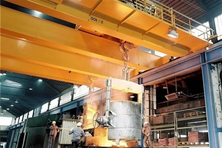
A casting bridge crane is a specialized type of overhead crane designed for handling molten metal in foundries, steel plants, and other high-temperature industrial environments. These cranes are built to withstand extreme heat, heavy loads, and harsh working conditions while ensuring safety and efficiency in metal casting operations.
Key Features of Casting Bridge Cranes:
High-Temperature Resistance
Made with heat-resistant materials (special steel, refractory coatings, or heat shields).
Protects critical components (wiring, motors, and hooks) from molten metal splashes.
Robust Construction
Heavy-duty steel structure to handle extreme loads (typically 5 tons to 500 tons).
Reinforced girders and end carriages for stability during casting operations.
Specialized Lifting Mechanisms
Ladle hook or forging hook for safely transporting molten metal ladles.
Optional tilting mechanism for precise pouring of molten metal.
Dual hoists for redundancy in critical applications.
Safety Systems
Overload protection to prevent crane failure.
Emergency stop and anti-sway technology for smooth handling.
Thermal insulation panels to shield electrical components.
Customizable Options
Explosion-proof motors (for hazardous environments).
Remote control operation for safer handling.
Automated positioning systems for precision pouring.
- Capacity: 5-800/50ton
- Span length: 4-35m
- Lifting height: 3-50m
- Work duty: A4, A5, A6,A7
- Raged voltage: 220V~690V, 50-60Hz, 3ph AC
- Work environment temperature: -25℃~+50℃, relative humidity ≤85%
- Crane control mode: Floor control / Remote control / Cabin room

Pictures & Components
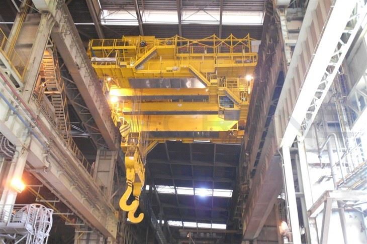
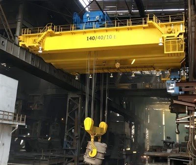
1. Whole set crane
Whole Set Casting Bridge Crane Components:
A complete casting bridge crane system typically includes:
Bridge Girder (Main Beam & End Carriages)
Double-girder design (common for heavy-duty applications).
Reinforced steel construction to handle high loads and thermal stress.
Heat-resistant paint or coatings to prevent corrosion from fumes.
Hoist & Trolley System
Electric Hoist (Wire rope or chain hoist) with high lifting capacity.
Explosion-proof or heat-resistant motors for safety in high-temperature zones.
Ladle hook or grab for handling molten metal or castings.
Crane Travel Mechanism
Longitudinal travel (along the runway rails).
Cross travel (trolley movement across the bridge).
Slewing mechanism (if required for precise positioning).
Runway System
Heavy-duty runway beams with rails.
End stops, buffers, and anti-collision devices.
Electrical & Control System
Pendant control / Radio remote control (for safe operation).
Variable Frequency Drive (VFD) for smooth movement.
Overload protection & emergency stop.
Heat-resistant cables & wiring.
Safety Features
Thermal insulation for critical components.
Double braking system for fail-safe operation.
Molten metal spill protection.
Limit switches & overload alarms.

2. Main girder
The main girder of a casting bridge crane is a critical load-bearing component that supports the hoist and trolley, enabling the crane to lift and transport heavy loads in foundries, steel mills, and other industrial settings. Below are key aspects of the main girder in a casting bridge crane:
1. Design & Construction
Material: Typically made of high-quality steel (Q235B, Q345B) for strength and durability.
Structure:
Box girder: Common in modern designs, offering high rigidity and resistance to torsional forces.
I-beam girder: Used in lighter-duty applications.
Welding & Fabrication: Precision-welded to ensure structural integrity, often with ultrasonic testing (UT) for quality control.
2. Key Features
High Heat Resistance: Since casting cranes operate near molten metal, the girder may have heat-resistant coatings or refractory protection.
Stiffness & Deflection Control: Designed to minimize deflection under load (typically ≤ 1/700 to 1/1000 of the span).
Corrosion Protection: Painted with epoxy zinc-rich primer or other anti-corrosive treatments.
3. Load Capacity
Casting bridge cranes usually have high load capacities (e.g., 5T to 500T), requiring robust girder design.
Dynamic Load Consideration: Accounts for lifting shocks and molten metal splashes.
4. Manufacturing Standards
Complies with ISO, FEM, DIN, or GB standards (e.g., GB/T 14405 for overhead cranes).
May include explosion-proof or heat-resistant modifications for harsh environments.
5. Integration with Crane Components
Supports the hoist (electric or hydraulic) and trolley.
Connected to end carriages (with wheels) that run on rails.
May include anti-sway or automation systems for precise load handling.
6. Customization Options
Span length: Adjustable based on workshop requirements.
Double-girder vs. Single-girder:
Double-girder offers higher capacity and stability.
Single-girder is cost-effective for lighter loads.
Special coatings for extreme heat or corrosive environments.
7. Maintenance & Inspection
Regular checks for cracks, deformation, or corrosion.
Lubrication of moving parts.
Non-destructive testing (NDT) for hidden defects.
Conclusion
The main girder is the backbone of a casting bridge crane, requiring high strength, heat resistance, and precision engineering to ensure safe and reliable operation in demanding industrial environments.

3. Lifting System
A casting bridge crane lifting system is a specialized overhead crane used in foundries, steel mills, and heavy manufacturing environments to handle molten metal, castings, and other high-temperature materials. These cranes are designed for durability, precision, and safety in harsh conditions.
Key Components of a Casting Bridge Crane Lifting System
Bridge Girder
Made of heavy-duty steel to withstand high loads and thermal stress.
Often reinforced with heat-resistant materials for molten metal applications.
End Trucks (End Carriages)
Equipped with rugged wheels and drive mechanisms for smooth movement along runway rails.
May include heat shields to protect from radiant heat.
Hoisting Mechanism
Main Hoist: Handles the primary lifting of ladles, molds, or castings.
Auxiliary Hoist (optional): For secondary lifting tasks.
Wire Rope or Chain Hoist: Selected based on load capacity and temperature resistance.
Trolley System
Moves horizontally along the bridge girder for precise load positioning.
May include a rotating trolley for ladle pouring applications.
Ladle Handling Attachment (for Foundry Cranes)
Specialized hooks, grabs, or tilting mechanisms for molten metal transfer.
Heat-resistant materials (e.g., refractory-coated hooks).
Control System
Pendant Control (manual) or Radio Remote Control (for operator safety).
Variable speed drives for smooth operation.
Overload protection and emergency stop functions.
Safety Features
Thermal Insulation to protect from heat radiation.
Redundant Braking System for fail-safe operation.
Anti-Sway Technology for precise load handling.
Spark-Resistant Electrical Components (in explosive atmospheres).

4. End Carriages
End carriages are critical components of bridge cranes that support and facilitate the movement of the crane along the runway rails. For casting bridge cranes (where major components are cast rather than fabricated), the end carriages have some unique characteristics.
Typical Features of Casting Bridge Crane End Carriages:
Material Construction:
Typically made from high-quality cast steel (GS or ASTM standards)
Provides excellent strength and durability
Allows for complex shapes that would be difficult with fabrication
Design Elements:
Integrated bearing housings for wheels
Reinforced structural design to handle dynamic loads
Often include built-in lubrication systems
May incorporate vibration damping features
Wheel Configuration:
Usually 4 wheels per end carriage (2 driven, 2 idle)
Wheel diameters sized for the load capacity
Options for single or double flange wheels depending on rail type
Drive System Integration:
Mounting points for drive motors and reducers
Provisions for brake systems
Alignment features for proper gear mesh
5. Crane traveling mechanism
The traveling mechanism of a casting bridge crane is a critical component that enables the crane to move along the runway rails, facilitating the transportation of molten metal, ladles, or other heavy loads in foundries, steel plants, and metallurgical industries. Below is a detailed breakdown of its components, working principle, and key features:
1. Components of the Traveling Mechanism
The traveling system typically consists of the following parts:
A. Drive Unit
Electric Motors (usually AC or DC, with high torque for heavy loads)
Brakes (fail-safe, often electromagnetic or hydraulic disc brakes)
Gearboxes (reduces motor speed to increase torque for smooth movement)
Couplings (connects motor to gearbox and wheels)
B. Wheels & Rails
Travel Wheels (forged steel or ductile iron, often heat-treated for durability)
Double-flanged wheels to prevent derailment.
Runway Rails (heavy-duty steel rails, typically QU80, QU100, or QU120 for high load capacity).
C. End Carriages (Bogies)
Support the crane's girders and house the wheels, bearings, and drive mechanisms.
May include anti-derailment guards or buffer stops for safety.
D. Control System
Variable Frequency Drives (VFDs) for smooth acceleration/deceleration.
Limit switches to prevent over-travel.
Remote or cabin-operated controls.
2. Working Principle
Power Supply: The electric motor receives power from the crane's electrical system.
Torque Transmission: The motor's rotation is reduced by the gearbox and transmitted to the wheels via couplings.
Movement: The wheels rotate along the runway rails, moving the entire crane bridge.
Braking: Electromagnetic or hydraulic brakes engage when power is cut or during emergencies.
6. Trolley traversing mechanism
The trolley traversing mechanism is a critical component of a casting bridge crane, responsible for moving the trolley horizontally along the bridge girder(s). This mechanism ensures precise positioning of the hoist for lifting, transporting, and placing loads in foundries, steel mills, and other heavy industrial applications.
Components of the Trolley Traversing Mechanism
Drive Motor
Typically an AC/DC electric motor or variable frequency drive (VFD) motor for smooth acceleration/deceleration.
Selected based on speed, duty cycle, and load capacity.
Reduction Gearbox
Converts high-speed motor output to low-speed, high-torque motion.
Common types: helical gearbox, planetary gearbox, or worm gearbox (for heavy-duty applications).
Wheels & Rail System
Wheels: Typically forged steel wheels with high load-bearing capacity.
Rail: Runs along the bridge girder; can be flat-top rails or grooved rails depending on design.
Some designs use double-flanged wheels to prevent derailment.
Braking System
Electromagnetic brakes or hydraulic disc brakes ensure safe stopping.
May include fail-safe brakes for emergency stops.
Coupling & Drive Shaft
Connects motor to gearbox (flexible couplings reduce vibration).
In dual-drive systems, a longitudinal drive shaft synchronizes both sides.
Bearings & Axles
Heavy-duty anti-friction bearings (tapered roller bearings) support wheel rotation.
Axles are hardened steel for durability.
Limit Switches & Encoders
Limit switches prevent over-travel at bridge ends.
Encoders provide position feedback for precise control (critical in automated foundries).
Optional Features
Anti-sway systems for precise load positioning.
Cable reeling system for power supply to the trolley.
7. Crane wheel
1. Types of Crane Wheels
Forged Steel Wheels: High strength, durable, and commonly used for heavy-duty cranes.
Cast Steel Wheels: Good for moderate to heavy loads, often used in foundries or high-temperature environments.
Ductile Iron Wheels: Suitable for lighter to medium loads, cost-effective but less durable than steel.
Nylon/Polyurethane Wheels: Used for light-duty cranes or where noise reduction is needed.
2. Key Considerations for Casting Crane Wheels
Material Selection:
Cast Steel (ZG340-640, ZG50Mn2, ZG42CrMo) for high-load applications.
Ductile Iron (QT500-7, QT600-3) for medium-duty cranes.
Heat Treatment:
Hardening (quenching & tempering) improves wear resistance.
Wheel Tread Profile:
Flat tread for flat rails.
Conical or tapered tread for crowned rails (helps with alignment).
Flange Design:
Single flange (for one-sided guidance).
Double flange (for better rail retention).
3. Common Wheel Defects in Casting & Solutions
Porosity/Shrinkage → Proper gating/riser design in casting.
Cracks → Controlled cooling & post-casting heat treatment.
Wear & Spalling → Use high-carbon alloys or hardened surfaces.
4. Standard Wheel Dimensions
Diameter: Typically ranges from 200mm to 1000mm (depends on crane capacity).
Width: Matches rail head width (e.g., 50mm to 150mm).
Bore Size: Matches axle diameter (often 60mm to 200mm).

8. Crane hook
1. Types of Casting Crane Hooks
Single Hook: Used for moderate loads, common in general-purpose lifting.
Double Hook: Designed for heavier loads, offering better weight distribution.
Eye Hook: Features an eye for attaching slings or chains.
Shank Hook: Has a threaded or forged shank for direct attachment.
2. Materials Used
Alloy Steel (e.g., 20CrMo, 35CrMo): High strength and toughness, heat-treated for durability.
Carbon Steel (e.g., ASTM A148, Grade 80-100): Good balance of strength and cost.
Stainless Steel (for corrosive environments): Used in marine or chemical industries.
3. Manufacturing Process
Sand Casting: Common for large hooks, cost-effective.
Investment Casting (Lost Wax): Precision casting for complex shapes.
Die Casting: Used for mass production with tight tolerances.
Forged Hooks (Alternative): Sometimes preferred for higher fatigue resistance.
4. Key Features
Load Capacity: Rated for specific working loads (e.g., 1T to 500T).
Safety Factor: Typically 4:1 or 5:1 (breaking load vs. working load).
Surface Treatment: Machining, shot blasting, galvanizing, or painting.
Inspection & Testing: Ultrasonic, magnetic particle, or dye penetrant testing.
5. Standards & Certifications
ISO 9001: Quality management.
ASME B30.10: Hooks-Safety standards.
FEM 1.001: European standards for lifting equipment.
DIN 15400: German standards for crane hooks.

9. Motor
Key Considerations for Motor Selection:
Duty Cycle & Load Classification
Casting cranes typically operate under heavy-duty (H3 or H4) or continuous-duty conditions due to high temperatures and frequent usage.
Motors should comply with FEM, ISO, or CMAA standards for duty classification.
Motor Type
AC Induction Motors (Squirrel Cage or Slip Ring): Common for general crane movements.
Variable Frequency Drive (VFD) Motors: Essential for smooth acceleration/deceleration to prevent molten metal splashing.
Explosion-Proof Motors (if required): Needed in hazardous environments with flammable gases.
Thermal Resistance & Cooling
Insulation Class (F or H): High-temperature resistance due to radiant heat from molten metal.
Forced Ventilation (IC 416) or Totally Enclosed Fan-Cooled (TEFC): Prevents dust and heat damage.
Power & Speed Requirements
Hoisting Motor: High torque at low speed for precise lifting.
Trolley/Travel Motors: Smooth movement control with variable speed.
Common power range: 5 kW to 200 kW+ depending on capacity (usually 10–100 tons for casting cranes).
Safety & Redundancy
Fail-safe brakes (dual-disc brakes for hoisting).
Overload protection & temperature sensors.
Redundant motors may be required for critical applications.
Environmental Protection
IP55 or higher for dust and moisture resistance.
Special coatings to resist corrosive fumes in foundries.


10. Sound and light alarm system & limit switch
1. Sound and Light Alarm System
The sound and light alarm system on a casting bridge crane serves as a warning mechanism to alert workers of crane movements, potential hazards, or emergency situations.
Functions:
Startup Warning: Activates before the crane begins moving to notify nearby personnel.
Overload Alert: Triggers when the load exceeds safe capacity.
Emergency Stop: Sounds an alarm if an emergency stop is activated.
Approaching Limit: Warns when the crane is nearing its travel limits (activated by limit switches).
Fault Indication: Alerts operators to electrical or mechanical failures.
Components:
Horn/Siren: Emits loud audible warnings.
Strobe Lights/Beacons: Provides visual warnings, especially useful in noisy environments.
Control Panel Integration: Linked with PLC or relay logic to activate alarms based on sensor inputs.
2. Limit Switches
Limit switches are safety devices that prevent the crane (or its hoist/trolley) from moving beyond its designated travel range. They are crucial for avoiding collisions, overtravel, and mechanical damage.
Types of Limit Switches in a Casting Bridge Crane:
Hoist Upper/Lower Limit Switch
Prevents the hoist from over-raising (which could damage the wire rope) or over-lowering (which could cause slack rope hazards).
Typically a rotary limit switch or proximity sensor.
Bridge & Trolley Travel Limit Switches
Stops the crane or trolley at the end of the runway or girder.
Uses lever-arm limit switches or magnetic proximity sensors.
Anti-Collision Limit Switch
Used in facilities with multiple cranes to prevent collisions.
Often employs infrared or ultrasonic sensors in addition to mechanical switches.
Emergency Limit Switch (Hardwired Override)
A failsafe switch that cuts power if other limits fail.
Working Principle:
When the crane or hoist reaches a set limit, the switch is triggered, cutting power or reversing motion.
Can be normally open (NO) or normally closed (NC) depending on the safety circuit design.

11. Safety Devices
1. Overload Protection Devices
Load Limiters / Overload Sensors – Prevent the crane from lifting beyond its rated capacity.
Load Cells / Weighing Systems – Monitor real-time load weight and trigger alarms if overloaded.
2. Emergency Stop Systems
E-Stop Buttons – Installed at multiple locations (cabin, ground, remote) for immediate shutdown.
Fail-Safe Brakes – Automatically engage in power loss or emergency stops.
3. Anti-Collision Systems
Laser/Ultrasonic Sensors – Detect obstacles or other cranes to prevent collisions.
Rail End Buffers & Limit Switches – Stop crane movement at track ends.
4. Molten Metal-Specific Protections
Thermal Shields & Heat-Resistant Components – Protect electrical systems from radiant heat.
Ladle Safety Hooks & Clamps – Secure ladles to prevent spills.
Slip Clutch Mechanisms – Prevent sudden drops if motor/gearbox fails.
5. Electrical Safety Features
Undervoltage Protection – Prevents operation during power fluctuations.
Short-Circuit & Phase Failure Protection – Guards against electrical faults.
Insulated Controls – Protects operators from electrical hazards.
6. Operator Safety Systems
Anti-Sway Control – Stabilizes load movement to prevent swinging.
Two-Hand Control (Where Applicable) – Ensures operator attentiveness.
Cabin Fire Extinguishers – For emergency fire suppression.
7. Monitoring & Alarms
Warning Lights & Horns – Alert personnel before crane movement.
Anemometer (for Outdoor Cranes) – Detects high winds and restricts operation.
CCTV & Remote Monitoring – Enhances visibility for the operator.
8. Structural Safety Measures
Crack & Deformation Sensors – Detect structural weaknesses.
Redundant Hoist Systems – Backup lifting mechanisms for critical applications.
12. Control Mode
The control mode of a casting bridge crane (also known as a foundry crane or ladle crane) is crucial for safe and efficient operation, especially in high-temperature and hazardous environments like steel mills or foundries. Here are the common control modes used for casting bridge cranes:
1. Cab Control (Operator Cabin)
An operator sits in an air-conditioned, insulated cabin (often heat- and splash-proof) to control the crane.
Provides direct visibility of the lifting process, which is critical for handling molten metal.
Suitable for heavy-duty, high-precision operations where real-time monitoring is essential.
2. Pendant Control (Push Button Pendant)
A pendant station (wired or wireless) allows the operator to control the crane from the floor.
Used for short-distance movements or auxiliary operations.
Often explosion-proof or heat-resistant for foundry environments.
May be combined with radio remote control for flexibility.
3. Radio Remote Control (Wireless)
The operator uses a handheld remote to control the crane from a safe distance.
Reduces exposure to heat, fumes, and molten metal splashes.
Often IP-rated (dust/water-resistant) and heat-shielded.
Requires fail-safe mechanisms (e.g., emergency stop, signal loss protection).
4. Semi-Automatic & Automatic Control
Pre-programmed movements for repetitive tasks (e.g., pouring molten metal into molds).
Automated ladle positioning with PLC-based control for precision.
May include weighing systems to monitor molten metal levels.
Used in modern foundries for efficiency and safety.
5. Dual Control (Combination of Cab + Remote)
Allows switching between cab and remote control depending on the operation.
Enhances flexibility and safety in hazardous environments.


13. Sketch

Main Technical Data

Advantages
A casting bridge crane is a type of overhead crane specifically designed for use in foundries, steel mills, and metal casting environments, where high temperatures, heavy loads, and harsh conditions are common. Here are the key advantages of using a casting bridge crane:
1. High Heat Resistance
Designed with heat-resistant materials (such as high-grade steel or special coatings) to withstand extreme temperatures in foundries and steel plants.
Insulated components (e.g., wiring, motors) to prevent damage from radiant heat.
2. Heavy-Duty Lifting Capacity
Built to handle extremely heavy loads (often 50 tons to 500+ tons), making them ideal for molten metal handling, ladles, and large castings.
Reinforced girders and robust hoists ensure safe lifting of heavy materials.
3. Enhanced Safety Features
Double-girder design for better stability when transporting molten metal.
Fail-safe brakes, overload protection, and emergency stop systems to prevent accidents.
Anti-sway technology for precise load positioning, reducing spill risks.
4. Corrosion & Wear Resistance
Special protective coatings (e.g., zinc plating, heat-resistant paint) to resist oxidation and corrosion from fumes, dust, and moisture.
Durable wheels and tracks for long-term use in harsh environments.
5. Precision & Control
Variable-speed controls for smooth handling of delicate or hazardous loads (e.g., molten metal).
Remote control or cabin-operated options for safer operation in high-temperature zones.
6. Customizable for Foundry Use
Can be equipped with ladle hooks, grab buckets, or specialized lifting attachments for casting applications.
Explosion-proof options available for hazardous environments.
7. Low Maintenance & Long Service Life
Built with heavy-duty components that require minimal maintenance despite harsh working conditions.
Sealed bearings and lubrication systems to prevent dust and metal particle contamination.
8. Improved Productivity
Enables efficient transport of molten metal, molds, and finished castings, reducing manual labor and speeding up production.
Reduces downtime with reliable performance in extreme industrial settings.
Application
A casting bridge crane is a specialized type of overhead crane used in foundries and metal casting facilities to handle molten metal, molds, and heavy castings. These cranes are designed to withstand high temperatures, heavy loads, and harsh environments.
Applications of Casting Bridge Cranes
Molten Metal Handling
Transporting ladles filled with molten metal from furnaces to casting areas.
Pouring molten metal into molds with precision.
Mold Handling
Moving sand molds, die-cast molds, or other casting molds.
Positioning molds for pouring and cooling.
Casting Removal & Finishing
Transferring freshly cast parts to cooling beds or shakeout systems.
Transporting finished castings to machining or finishing areas.
Foundry Operations
Assisting in furnace charging with raw materials (scrap, ingots).
Supporting cleaning, grinding, and inspection processes.
Crane Production Procedure
1. Design & Engineering
Requirements Analysis: Determine load capacity, span, lifting height, and operating environment.
CAD Modeling: Create 3D designs and structural calculations (stress analysis, deflection, etc.).
Material Selection: Choose suitable casting materials (typically cast steel or ductile iron) for key components like girders, end carriages, and hooks.
Regulatory Compliance: Ensure designs meet standards (ISO, DIN, FEM, or ASME).
2. Pattern Making & Mold Preparation
Pattern Creation: Wood or metal patterns are made for casting molds.
Sand Mold Preparation:
Use resin-bonded sand or green sand for mold cavities.
Cores (for hollow sections) are prepared separately.
3. Casting Process
Melting & Pouring:
Metal (e.g., carbon steel, alloy steel) is melted in a furnace.
Molten metal is poured into molds under controlled conditions.
Cooling & Solidification: Allow the casting to cool slowly to avoid defects.
Shakeout & Cleaning: Remove sand molds, and clean castings (shot blasting, grinding).
4. Machining & Finishing
Rough Machining: Remove excess material (gates, risers).
Precision Machining: CNC machining for critical dimensions (bearing seats, bolt holes).
Surface Treatment: Painting, galvanizing, or anti-corrosion coatings.
5. Fabrication of Bridge Girder & End Carriages
Welding/Assembly:
Fabricate box girders or I-beams (if hybrid design).
Weld/bolt end carriages (with wheels for movement).
Stress Relief Heat Treatment (if needed) to reduce residual stresses.
6. Assembly of Crane Components
Hoist & Trolley Installation: Mount electric hoist or wire rope system.
Rail & Runway Setup: Install crane rails on supporting structure.
Electrical System Integration: Wire motors, controls, limit switches, and safety devices.
7. Testing & Quality Control
Dimensional Inspection: Verify tolerances per design specs.
Non-Destructive Testing (NDT):
Ultrasonic, magnetic particle, or dye penetrant testing for cracks.
Load Testing:
Static Load Test: 125% of rated capacity.
Dynamic Load Test: 110% of rated capacity with movements.
Functional Test: Check braking, lifting, and travel operations.
8. Painting & Corrosion Protection
Apply primer and corrosion-resistant paint.
Markings (capacity, serial number, warnings) as per standards.
9. Packaging & Delivery
Disassemble (if needed) for shipping.
Protect critical components during transit.
10. Installation & Commissioning (On-Site)
Reassemble on the customer's runway.
Final alignment and calibration.
Operator training and handover.

Workshop View
The company has installed an intelligent equipment management platform, and has installed 310 sets (sets) of handling and welding robots. After the completion of the plan, there will be more than 500 sets (sets), and the equipment networking rate will reach 95%. 32 welding lines have been put into use, 50 are planned to be installed, and the automation rate of the entire product line has reached 85%.


Hot Tags: casting bridge crane, China casting bridge crane manufacturers, suppliers, factory, Metallurgical Overhead Crane, Metallurgical Crane, Casting Overhead Ladle Crane
Previous
20m Span Overhead CraneYou Might Also Like


Send Inquiry