







QD-32t-double-girder-overhead-crane
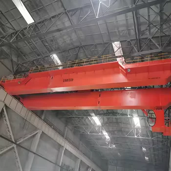
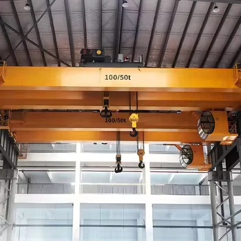
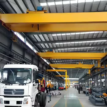
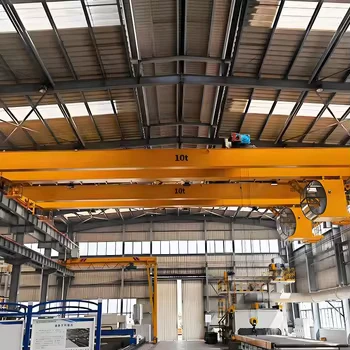
A QD 32t Double Girder Overhead Crane is a heavy-duty industrial crane designed for use in heavy manufacturing workshops, steel warehouses, fabrication bays, and assembly plants. It is capable of handling heavy and demanding material handling tasks up to 32 tons, and is ideal for moving and positioning steel coils, heavy dies, machined components, and foundry ladles within the industrial facility.
These cranes typically feature two parallel welded box runways with a bridge that spans the gap between them. The bridge is mounted on forged steel wheels housed in end carriages, allowing it to travel smoothly along the runway rails. The winch and crab trolley system of the crane can be customized to meet the specific operational needs of your facility, such as higher load capacity, extended lifting heights, or variable-frequency stepless speed regulation.
QD 32t Double Girder Overhead Cranes are designed to withstand harsh operating conditions, such as high ambient temperatures, airborne dust, and intensive working shifts. They are also equipped with complete safety features, including emergency stop systems, rotary limit switches, and digital overload protection devices, to ensure safe and efficient operation.
Overall, the QD 32t Double Girder Overhead Crane is an essential piece of equipment in any heavy production or logistical operation. It provides a reliable and efficient means of moving heavy loads and machinery within the facility, helping to increase productivity while also ensuring worker safety.

Capacity: 32/5 ton (Main hook: 32t, Aux hook: 5t)
Span length: 10.5m – 35m (Design benchmark: 28m)
Lifting height: 6m – 30m (Design benchmark: 11.5m)
Work duty: ISO M6 / FEM 3m (Heavy Duty A6)
Rated voltage: 220V~480V, 50–60Hz, 3-Phase AC (Standard: 380V 50Hz)
Work environment temperature: -20℃~+40℃, relative humidity ≤85%
Crane control mode: Closed Cabin room / Radio remote control / Floor pendant control

Pictures & Components (Revised Copy)
1. Whole set crane
The QD 32t double girder overhead crane represents a robust, heavy-duty material handling solution engineered for high-intensity duty cycles across metal fabrication, die handling, heavy assembly, and logistics hubs. Featuring a rigid twin-girder bridge, an independent top-running winch crab, and synchronized end trucks, this unit provides precise three-axis load control. Operating under ISO M6 / FEM 3m classification, the crane easily manages frequent, full-load hoisting without thermal or mechanical fatigue.
2. Main girder
Fabricated from high-tensile structural steel (Q235B / Q355B), the twin box girders feature optimized internal diaphragms and full-penetration longitudinal welds. Automated submerged-arc welding pre-sets a precision camber curve of $(0.9 \sim 1.4 / 1000)S$, neutralizing deadweight and rated load deflection. Sturdy P38 heavy rails are welded along the upper flanges for the trolley runway, flanked by anti-slip checkered steel maintenance catwalks, kickplates, and tubular guardrails for routine servicing.
3. Lifting System
Hoisting duties are performed by a self-contained, open-winch crab trolley configured with dual independent hook circuits. The primary 32-ton hoist is driven by a 55 kW wound-rotor motor (YZR280M-8), coupled to an oil-bath hardened gear reducer (ZQ850, ratio 40.17) and dual electro-hydraulic thruster brakes (YWZ-400/90, 2×1600 N·m). For rapid auxiliary handling and turning bulky molds, an independent 5-ton secondary hoist operates via a 17 kW motor (YZR180L-6) and ZQ500 reducer, delivering brisk 15.5 m/min hook speeds.
4. End Carriages
The end carriages consist of rectangular hollow steel sections reinforced with internal stiffeners, forming an unyielding frame that keeps the bridge strictly orthogonal during travel.
Fitted with Ø800 mm double-flanged forged wheels driven by individual motor-gearbox units, these trucks eliminate crabbing and guide the crane smoothly along runway tracks. Removable pin-and-high-strength-bolt splice connections facilitate modular knockdown for standard ocean freight container loading.
Heavy-gauge polyurethane buffers and rail sweep plates are integrated at both extremities to mitigate impact shocks and clear runway debris.
5. Crane traveling mechanism
Long travel utilizes an independent dual-drive configuration (separated drive) powered by twin 7.5 kW wound-rotor motors (YZR160M2-6) paired with horizontal gearboxes (ZQ500, ratio 48.57). Delivering a calibrated travel speed of 48 m/min, this symmetrical traction architecture guarantees synchronized acceleration and dynamic deceleration, substantially eliminating cross-girder skew, wheel flange wear, and crane runway rail gnawing.
6. Trolley traversing mechanism
Cross travel across the 2,500 mm trolley gauge is powered by a 6.3 kW motor (YZR160M1-6) working through a compact vertical reducer (ZSC600, ratio 27.3) and a YWZ-200/25 thruster brake.
Operating at a steady traversing speed of 42.4 m/min, the drive train provides smooth starting torque and precise micro-positioning over heavy machinery beds.
Supported by mechanical travel stops and two-stage lever limit switches to prevent accidental over-travel at span ends.
7. Crane wheel
Engineered to withstand maximum operational wheel loads of 322 kN, all travel wheels are forged from vacuum-degassed 65Mn or 42CrMo alloy steel.
Tread contact surfaces and double flanges undergo deep intermediate-frequency induction quenching (HB 300–380, hardening depth ≥15 mm) to resist surface pitting and flange abrasion.
The wheel axles rotate on heavy-duty self-aligning spherical roller bearings secured in 45-degree split-type bearing housings for fast extraction and relubrication.
8. Crane hook
Both the 32t main hook and 5t auxiliary hook are die-forged from high-grade alloy steel (DG20 / DG34CrMo) in strict compliance with DIN 15401 specifications. The main hook assembly rests on a heavy-duty enclosed thrust ball bearing allowing smooth 360-degree rotation under maximum payload. Positive-locking, spring-return safety catches prevent lifting slings and rigging shackles from accidental disengagement during complex rigging maneuvers.
9. Motor
All crane motions are driven by heavy-duty wound-rotor slip-ring motors (YZR series) optimized for crane service and intermittent periodic operation (S3-40% / S3-60%). Built with Class F/H thermal insulation and IP54 sealed enclosures, these motors handle high pull-out torque, frequent plug braking, high switching frequencies, and dusty shop floor environments without overheating.
10. Sound and light alarm system & limit switch
Active workplace safety is maintained by high-output audible sirens (≥105 dB) combined with bright strobe warning lights that trigger automatically upon crane movement. The hoisting drums incorporate screw-driven rotary limit switches backed by gravity-actuated weight-type limit switches, establishing dual-redundant fail-safe protection against two-blocking and bottom wire rope over-unwinding.
11. Safety Devices
Electronic overload limiter: Connected to load-cell sensors, this system continuously displays hook loads in the cabin, cutting off hoisting power and activating an acoustic-optical alarm at 105% rated capacity.
Two-tier travel limiters: Proximity and lever-type limit switches decelerate and halt bridge and trolley motions before contacting end buffers.
Optical anti-collision system: Laser and infrared distance detectors prevent inter-crane impacts on shared runway systems.
Multi-point emergency stop: Pushbuttons located in the cab, along walkways, and on wireless transmitters isolate the main contactor instantly.
Electrical interlocks: Door limit switches prevent bridge travel whenever platform boarding gates or maintenance hatches are open.
12. Control Mode
Fully enclosed panoramic cabin: Glazed with safety tempered glass, equipped with master joystick linkage consoles, adjustable shock-absorbing operator seat, cabin fan, and split-system HVAC.
Industrial wireless radio remote: Ergonomic transmitter with proportional twin joysticks and a 100-meter operating radius, allowing the operator to steer clear of hazardous lift zones.
Suspended pendant station: Backup push-button controller sliding smoothly on an independent galvanized C-rail festoon cable track.
13. Sketch
(Dimensional Layout Reference based on Drawing QD32/5t-28m A6)
Span ($S$): 28,000 ± 5 mm
Trolley Track Gauge ($K$): 2,500 mm
Hook Approach Clearances: Left hook limit = 1,100 mm; Main-aux hook center distance = 871 mm; Right hook limit = 1,700 mm
End Carriage Wheelbase: 5,000 mm (Overall truck length: 6,340 mm)
Height Above Rail: 2,477 mm; Overhead safety clearance: $\ge$ 200 mm; Runway edge clearance: $\ge$ 100 mm

Span ($S$): 28,000 ± 5 mm
Trolley Track Gauge ($K$): 2,500 mm
Hook Approach Limits: Left hook limit = 1,100 mm; Hook center spacing = 871 mm; Right hook limit = 1,700 mm
End Carriage Wheelbase: 5,000 mm (Overall truck length: 6,340 mm)
Height Above Rail: 2,477 mm; Top safety clearance: $\ge$ 200 mm; Side clearance: $\ge$ 100 mm
Main Technical Data (QD 32/5t-28m A6 Engineering Benchmark)
| System / Mechanism | Parameter Item | Main Hoisting Mechanism | Auxiliary Hoisting Mechanism | Trolley Traveling | Crane Traveling |
| Rated Capacity (t) | Lifting Capacity | 32 t | 5 t | - | - |
| Operating Speed (m/min) | Working Speed | 9.5 m/min | 15.5 m/min | 42.4 m/min | 48 m/min |
| Duty Classification | Working Class (ISO/FEM) | M6 (A6) | M5 (A5) | M5 (A5) | M6 (A6) |
| Lifting Height / Span | Height / Span Length | 11.5 m | 11.5 m | Gauge: 2,500 mm | Span: 28,000 mm |
| Electric Motor Model | Motor Type | YZR280M-8 | YZR180L-6 | YZR160M1-6 | YZR160M2-6 |
| Motor Power & Speed | Power (kW) × RPM | 55 kW (725 r/min) | 17 kW (955 r/min) | 6.3 kW (921 r/min) | 2 × 7.5 kW (940 r/min) |
| Gear Reducer Model | Reducer Type | ZQ850-i-3CA | ZQ500-i-3CA | ZSC600-i-1 | ZQ500-i-1/2Z(Ø95) |
| Transmission Ratio (i) | Gear Ratio | i = 40.17 | i = 40.17 | i = 27.3 | i = 48.57 |
| Brake Model | Electro-Hydraulic Brake | YWZ-400/90 | YWZ-300/25 | YWZ-200/25 | YWZ-200/25 |
| Brake Torque (N·m) | Braking Torque | 2 × 1600 N·m | 320 N·m | 200 N·m | 2 × 200 N·m |
| Steel Wire Rope | Specification & Falls | 22NAT6×19W+FC1770 (8 falls) | 14NAT6×19W+FC1770 (4 falls) | - | - |
| Working Line Pull (kN) | Max. Working Rope Pull | 40.8 kN | 12.9 kN | - | - |
| Drum Dimension (mm) | Diameter × Length | Ø 650 × 2,000 mm | Ø 400 × 1,500 mm | - | - |
| Wheels & Max. Load | Diameter & Max. Wheel Load | - | - | 4 × Ø 400 mm (115.9 kN) | 4 × Ø 800 mm (322 kN) |
| Track Rail Model | Recommended Steel Rail | - | - | P38 | QU70 |
| Total Crane Mass (kg) | Deadweight Breakdown | Bridge: 30,770 kg | Crane Drive: 5,146 kg | Trolley: 12,250 kg | Total Weight: 50,184 kg |

Advantages
High Structural Rigidity: Fully automated submerged-arc welded box girders provide superior torsional and vertical stiffness, maintaining tight deflection limits under full 32-ton load.
Dual-Hook Working Efficiency: Separate main (32t) and auxiliary (5t) hoisting hooks optimize operational tempo by utilizing the 15.5 m/min fast aux hook for handling light loads and tilting heavy dies.
Low Maintenance Cost: Standardized components (ZQ gearboxes, YZR wound-rotor motors, YWZ brakes) ensure ready availability of spare parts worldwide.
Smooth Acceleration: Symmetrical separated drives and precision-machined forged wheels reduce rail gnawing, extending the life of runway tracks and building corbels.
High Hook Lift Clearance: Top-running winch trolley configuration maximizes available lifting height inside workshops compared to low-headroom hoists.
Broad Customizability: Easily fitted with variable frequency drives (VFD), motorized rotating hooks, grab buckets, electromagnets, or PLC positioning systems.
Application
Heavy machinery manufacturing, machining, and CNC assembly bays.
Steel mills, coil storage, and metal distribution centers.
Automotive die stamping, pressing, and engine assembly shops.
Precast concrete manufacturing and structural steel fabrication plants.
Power plants (hydro, thermal, wind) for turbine and generator maintenance.
Paper mill roller handling and general equipment repair workshops.
Railway maintenance depots and heavy logistics freight terminals.
Crane Production Procedure
Design and engineering: Structural finite element analysis (FEA), camber calculation, and clearance verification conforming to GB/T 14405, GB/T 3811, and ISO/FEM standards.
Material procurement: Strict incoming quality inspection for structural steel plates (Q235B / Q355B) and forged wheel billets with 100% mill test certificates.
CNC Cutting and shaping: Multi-head CNC flame and plasma cutting machines profile web plates with precise upward camber curves.
Automated Welding: Webs and flanges joined using automated twin-arc submerged arc welding (SAW) machines. Tension butt welds undergo ultrasonic (UT) flaw testing.
Shot blasting and coating: Entire steel structure blasted to ISO Sa2.5 grade, followed immediately by epoxy zinc-rich primer and polyurethane finishing coats.
Machining of drive components: Precision boring and milling of wheel axles, reducer mounting pads, and drum frames to ensure absolute alignment.
Modular Assembly: Factory integration of bridge girders, end carriages, trolley machinery, and conductor rail festoons.
Electrical installation: Wiring of centralized control panels, limit switches, inverters, and testing of alarm/interlock circuits.
Factory inspection and testing: No-load electrical commissioning, dimensional tolerance verification, and export packing protection before dispatch.

Workshop View
The company has installed an intelligent equipment management platform, and has installed 310 sets of handling and welding robots. After the completion of the plan, there will be more than 500 sets, and the equipment networking rate will reach 95%. 32 welding lines have been put into use, 50 are planned to be installed, and the automation rate of the entire product line has reached 85%.
Hot Tags: qd-32t-double-girder-overhead-crane, China qd-32t-double-girder-overhead-crane manufacturers, suppliers, factory, Double Girder Overhead Crane, Double Girder Overhead Travelling Crane
You Might Also Like


Send Inquiry