










160 Ton Boat Hoist Crane
Products Description
Primary Types of 160-Ton Boat Hoists
There are two main designs, each with its own advantages:
1. Marine Travel Lift
This is the most common and versatile type. It's a wheeled mobile crane that drives over a vessel in the water, lowers its slings, lifts the boat, and transports it to a storage yard.
Key Characteristics:
Mobility: Can move boats horizontally over land, making it ideal for yards with multiple storage spots.
Four-Point Lifting: Uses two wide, adjustable slings for stable and balanced lifting, distributing the 160-ton load evenly.
Capacity: A 160-ton model can typically lift vessels with a maximum weight of 160 US tons (approx. 145 metric tonnes).
Dimensions: The key specs are the span (distance between the legs, e.g., 30-40 feet) and the lift height (how high it can raise the boat). These must accommodate the beam (width) and air draft (height) of the target vessels.
Pros:
Highly flexible and mobile.
Can service multiple slips and work in confined spaces.
Generally lower initial investment than a Syncrolift.
Cons:
Requires a significant amount of paved land for maneuvering and storage.
Lifting capacity can be reduced when moving on an incline.
2. Shiplift / Syncrolift® (Platform Hoist)
This is a stationary system consisting of a large platform that is lowered into the water. The vessel is floated over it, and the platform is then raised, bringing the boat completely out of the water.
Key Characteristics:
Stationary Platform: The vessel is lifted in a perfectly level position.
Synchronized Hoisting: Multiple electric winches (or hydraulic cylinders) work in perfect sync to lift the platform evenly.
Transfer System: Once lifted, the platform can be paired with a multi-wheeled transport dolly to move the vessel to a work area.
Pros:
Extremely stable and level lift, ideal for hull inspections and repairs.
Can lift multiple vessels simultaneously if they fit on the platform.
Very efficient for high-volume facilities.
Cons:
Very high initial cost and complex installation.
Less flexible; vessels must be brought to the fixed platform.
Requires a dedicated pit and significant civil works.
Comparison with Other Boat Lifting Systems
| Feature | Gantry Boat Hoist | Marine Railway | Floating Dry Dock |
|---|---|---|---|
| Mobility | High (if rubber-tired) | Low (fixed track) | Low (water-dependent) |
| Max Capacity | 10–500+ tons | 50–5,000 tons | 1,000–100,000+ tons |
| Speed | Fast (minutes) | Slow (hours) | Moderate (hours) |
| Best For | Small to medium boats | Large ships | Massive vessels |
Comparison with Other Boat Lifting Systems
| Feature | Gantry Boat Hoist | Marine Railway | Floating Dry Dock |
|---|---|---|---|
| Mobility | ✅ High (if rubber-tired) | ❌ Fixed track | ❌ Water-dependent |
| Max Capacity | 10–500+ tons | 50–5,000 tons | 1,000–100,000+ tons |
| Speed | ⚡ Fast (minutes) | 🐢 Slow (hours) | 🕒 Moderate (hours) |
| Space Needed | Compact storage | Long track area | Large water area |
| Best For | Small-medium boats | Large ships | Massive vessels |
Lifting Capacity 160 tons
Span (Width) 3 - 12 meters (adjustable)
Lifting Height 3 - 10 meters
Working Class A3-A5 (light to medium duty)
Hoisting Speed 0.5 - 8 m/min (variable)
Main Beam Type Single/double girder (box-type)
Power Supply 220V/380V 3-phase or manual
Control Mode Pendant control/wireless remote
Hoist Type Electric chain hoist/wire rope hoist
Travel Drive Manual push or motorized
Corrosion Protection Hot-dip galvanized or marine-grade paint
Wind Resistance Up to Beaufort scale 6 (for outdoor use)
Operating Temp -20°C to +50°C

Pictures & Components
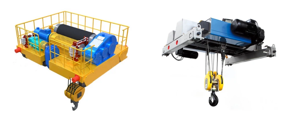
1. Structural Framework
This is the core skeleton that bears the entire load.
Main Girders / Bridge Beams: The two massive horizontal steel beams that span the width of the boat. They must be incredibly rigid to prevent bending under full load.
End Trucks / Leg Assemblies: The vertical structures at each end of the girders. They house the wheels, drive motors, and steering mechanisms. For a 160-ton hoist, these are substantial A-frame or box-section designs for stability.
Spreader Bar / Lifting Beam: A transverse beam that connects the two hoist units (see below) and distributes the load evenly to the main girders. This is a critical component for ensuring the slings hang vertically.
2. Hoisting and Lifting System
This system is responsible for the actual lifting and lowering of the vessel.
Winches / Hoist Units: Typically, there are two or four independent, synchronized electric or hydraulic winches. For a 160-ton capacity, two 80-ton winches or four 40-ton winches are common. They are mounted on the main girders.
Wire Ropes (Cables): High-strength, galvanized steel wire ropes wound on the winch drums. They are designed for heavy-duty cycles and are resistant to corrosion from the marine environment.
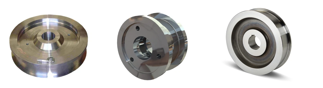
Sheaves / Pulleys: Large, grooved wheels mounted at the bottom of the end trucks that guide the wire ropes down to the slings. They are made of high-grade steel or sometimes nylon to be gentle on the wire rope.
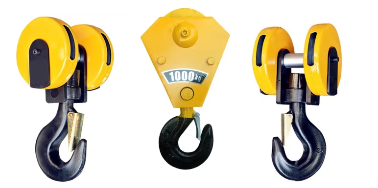
Lifting Hooks & Shackles: Massive, forged steel safety hooks and shackles connect the wire ropes to the slings. They are rated for the extreme loads and often have safety latches.

3. Sling System
This is the part that makes direct contact with the boat's hull and must be designed to support it without causing damage.
Slings: Heavy-duty, synthetic web slings (made from materials like polyester or nylon) are standard. They are wide to distribute pressure and are much gentler on hull finishes than wire or chain. A 160-ton hoist will have multiple slings, often in a "2-point" or "4-point" configuration.
Sling Spreader Bars: Used to keep the slings apart and properly positioned under the boat's hull. This prevents the slings from pinching the hull and ensures the load is taken at the boat's strong points (e.g., keel blocks and hull chocks).
4. Propulsion and Travel System
This system allows the entire crane to move around the boatyard.
Wheels and Tires: Typically, eight or more large, solid rubber tires (to prevent flats) or steel wheels on a rail system. The tires have a wide footprint to minimize ground pressure.
Drive Motors: Electric or hydraulic motors powering the wheels. They are usually located in the end trucks.
Steering System: A complex hydraulic system that allows the operator to steer all wheels simultaneously. Modes include:
Crab Steering: All wheels turn in the same direction, allowing the crane to move diagonally.
Circle Steering: The front and rear wheels turn in opposite directions, allowing for a very tight turning radius.
Two-Wheel Steering: Standard steering for straight travel.


6. Control and Operator Interface
The "brain" of the crane.
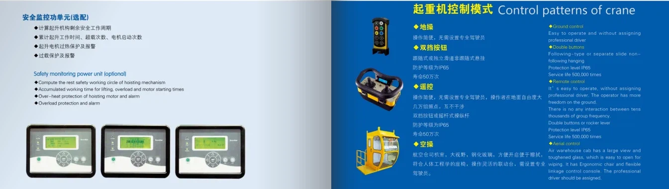
Operator's Cabin: An enclosed, climate-controlled cabin mounted on the crane frame, giving the operator an elevated, clear view of the boat and the lifting area.
Remote Control / Pendant: Many modern hoists also offer a wireless remote control, allowing the operator to walk alongside the boat for the best possible view during critical lifting and positioning maneuvers.

Control System / PLC: A Programmable Logic Controller (PLC) is the computer that runs the crane. It ensures:
Synchronization: That all hoists lift and lower at exactly the same rate to keep the boat level.
Overload Protection: Monitors the load on each hoist to prevent exceeding the crane's capacity.
Diagnostics: Provides fault codes and system status information.
7. Safety Systems
Critical features to protect both the vessel and the equipment.
Overload Limit Switches: Automatically cut power to the hoist if the load exceeds a safe threshold (e.g., 110% of rated capacity).
Upper/Lower Limit Switches: Prevent the hoist hooks from traveling too high and damaging the machinery or too low and spooling out too much cable.
Emergency Stop Buttons: Located at multiple points, including the cabin and remote control, for immediate shutdown.
Anti-Collision Systems: Sensors or physical buffers on the end trucks to prevent collisions with other yard equipment or structures.
Braking Systems: Multiple redundant brakes-mechanical brakes on the winches, and braking systems on the drive motors.
Applications of Each Component
| Component | Function |
|---|---|
| Gantry Frame | Supports entire structure |
| Winches & Slings | Lifts the boat |
| Trolley System | Positions boat over storage area |
| Steering Mechanism | Allows precise maneuvering |
| Load Sensors | Ensures safe lifting capacity |
SKETCH
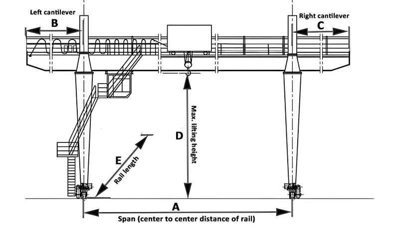
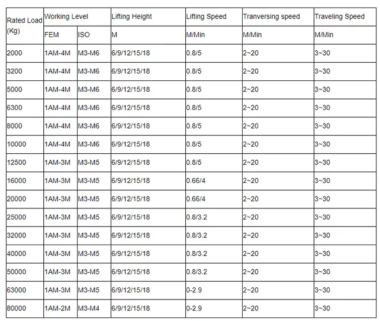
Main technical
Advantages
1. Operational Efficiency and Speed
Rapid Launch and Retrieval: The process of lifting a vessel from the water and moving it to a storage yard (or vice-versa) is incredibly fast. This allows a marina or boatyard to service more vessels in less time, increasing throughput and revenue.
Quick Turnaround for Maintenance: For boat owners needing bottom painting, hull repairs, or propeller servicing, the quick in-and-out capability minimizes the time the boat is out of the water, getting them back to sea faster.
Independent Operation: Unlike a railway system that moves multiple boats in a line, a travelift can service any boat in the yard independently without needing to move others.
2. Versatility and Flexibility
Wide Capacity Range: A 160-ton crane doesn't just lift 160-ton boats. It can efficiently and safely handle a wide range of vessels, from much smaller recreational boats up to its maximum capacity (e.g., large yachts, commercial fishing vessels, patrol boats). This makes it a highly versatile single-piece asset for a boatyard.
Handles Various Hull Shapes: It can lift monohulls, catamarans, and trimarans with the proper sling configuration, unlike some railway systems that can struggle with non-traditional hull forms.
Mobility: The crane is mobile on rubber tires, allowing it to move boats directly from the lift well to a specific parking spot in the storage yard, often in tight spaces. This optimizes yard space utilization.
3. Safety and Vessel Integrity
Even Weight Distribution: Modern boat hoists use multiple slings (typically 4 or more) that can be adjusted independently. This allows for a perfectly balanced lift, cradling the hull and preventing points of excessive stress that could cause hull damage.
Reduced Risk of Damage: Compared to beaching or using a railway, the gentle lift and placement significantly reduce the risk of scraping, grounding, or impact damage to the hull, keel, or running gear.
Enhanced Control: Operators have precise control over the lifting and lowering process, allowing for careful maneuvering in challenging conditions.
4. Space and Infrastructure Optimization
High-Density Storage: By lifting boats clear of the ground, they can be stored in multi-level racks or packed tightly together in a yard, vastly increasing storage capacity compared to water-based berthing.
Minimal Civil Works Required: While the yard needs reinforced pathways, a travelift requires a much simpler and less expensive infrastructure compared to the fixed slopes, piers, and underwater tracks needed for a railway system.
No Siltation Issues: Unlike a railway or synchrolift that requires a dredged pit, a travelift lift area is simpler to maintain and not prone to silting up.
5. Economic Advantages
Increased Revenue Potential: The speed and efficiency directly translate to the ability to service more customers.
Lower Operating Costs: While a significant capital investment, its operational costs are often lower than maintaining complex railway systems or the large pumping systems of a synchrolift.
Attracts Larger Vessels: Having a 160-ton capacity allows a marina to attract larger, more valuable yachts and commercial vessels, which command higher service fees.
6. Protection and Security
Storm Safety: In regions prone to hurricanes or severe storms, boats can be quickly lifted and securely stored on land, where they are far less vulnerable to damage than in the water.
Theft and Vandalism Deterrence: Storage in a secured, well-lit yard is a major deterrent compared to a boat left in a slip.
Blister Prevention: For fiberglass boats, being stored out of the water for extended periods prevents water absorption and the formation of osmotic blisters.
Application
Primary Applications of a 160-Ton Boat Hoist Crane
This capacity class is suited for a wide range of substantial vessels. The 160-ton rating typically refers to the total lifting capacity, which is distributed across multiple slings.
1. Boat Yard and Marina Operations:
Dry Stack Storage: This is the most common application. Instead of keeping boats in costly wet slips, marinas use the hoist to lift them onto a storage rack system, maximizing space and protecting the hulls from marine growth and damage.
Haul-Out and Launch: The fundamental job of moving boats from the water to dry land (haul-out) and back into the water (launch) for seasonal storage or to prepare for travel.
2. Ship Repair and Maintenance:
Hull Inspection and Cleaning: Allows for thorough inspection of the hull, propeller, rudder, and through-hull fittings.
Repairs: Essential for performing below-the-waterline repairs, such as fixing hull damage, replacing zinc anodes, repairing propellers and shafts, and repainting with anti-fouling coatings.
Survey and Compliance: Facilitates regulatory inspections and surveys required by classification societies and insurance companies.
3. Commercial and Industrial Use:
Fishing Fleets: Lifting large commercial fishing boats for net repairs, engine work, and hull maintenance during off-seasons.
Workboats: Servicing tugboats, pilot boats, crew transfer vessels, and barges.
Yacht Building and Refit: In shipyards, these cranes are used to move and position large hulls during the construction process or for major refit projects on mega-yachts.
4. Emergency and Salvage Operations:
Boat Recovery: Can be used to lift and recover sunken or grounded vessels that are within its weight capacity.
Emergency Dry-Docking: Quickly hauling a damaged boat out of the water to prevent it from sinking or to perform emergency repairs.
Crane production process
Phase 1: Design & Engineering
This is the most critical phase, where the crane's performance, safety, and durability are defined.
Client Requirements & Site Analysis:
Capacity & Span: The 160-ton capacity is the primary driver. Engineers determine the required span (the distance between the crane's runways) to cover the intended work area (e.g., a dry dock, marina pier).
Lift Height & Speed: The distance the boat must be lifted and the desired operational speed are defined.
Environmental Conditions: Wind loads, seismic activity, and corrosion potential (saltwater environment is a major factor) are analyzed.
Standards & Compliance: The design must adhere to international standards like ISO, FEM, DIN, ASME, or specific national regulations.
Structural Design & Calculations:
Finite Element Analysis (FEA): Software is used to create a 3D model of the entire crane structure. FEA simulates the stresses, deflections, and load paths under various conditions (full load, side wind, emergency stop) to ensure structural integrity.
Component Sizing: The main girders, end carriages, hoisting machinery, and wheels are precisely sized based on the calculations.
Electrical & Control System Design: The power requirements, motor sizes, variable frequency drives (VFDs for smooth operation), and the control system (pendant, radio remote, or cabin) are designed.
Detailed Drafting:
Production-ready drawings, including assembly diagrams, detailed part drawings, and bill of materials (BOM), are created for the workshop.
Phase 2: Material Procurement & Preparation
Main Materials: High-strength, low-alloy (HSLA) steel plates (e.g., S355, A572) are sourced for the main girders and structures. The steel is often certified with mill test reports.
Components: Pre-manufactured components are procured:
Hoisting Unit: High-capacity wire rope hoists (often multiple hoists in parallel for 160-ton capacity).
End Carriage Drives: Travel motors, gearboxes, and wheels.
Electrical Components: Motors, VFDs, PLCs, safety limit switches, and power collection systems (festoon or conductor bar).
Material Preparation: Steel plates are cut to size using CNC plasma or oxy-fuel cutting machines for precision.
Phase 3: Fabrication & Manufacturing
This is the hands-on phase where the crane is built.
Fabrication of Main Girders (Bridge):
Sub-Assembly: Cut plates are welded into I-beams or box girders. For a 160-ton crane, the girders are typically large box sections for superior strength and rigidity.
Welding: This is a critical step. Automated submerged arc welding (SAW) is often used for long, critical seams to ensure deep penetration and high consistency. All welds are performed by certified welders.
Stress Relieving: After major welding, the girders may be heat-treated in a large furnace to relieve internal stresses created during welding, preventing future distortion or cracking.
Fabrication of End Carriages:
These are the structures that house the wheels and travel drives. They are fabricated with high precision to ensure proper wheel alignment and squareness.
Machining:
Critical surfaces, such as the rail running surfaces on the end carriages and connection points, are machined on large boring mills or planers to achieve the required flatness and tolerances.
Phase 4: Assembly & Integration
The fabricated components and purchased parts are brought together.
Mechanical Assembly:
The main girders are bolted or welded to the end carriages to form the complete bridge.
The hoist units are installed onto the bridge girders on their respective runways.
The travel drive assemblies (motors, gearboxes, brakes) are mounted onto the end carriages.
Electrical & Control System Installation:
All electrical components are installed: motors, VFDs, the main control panel, and the operator's interface.
Cabling is run through cable trays and connected.
Safety devices are installed and wired: overload limit switches, end-of-travel limit switches, anti-collision systems, and anemometers (wind speed sensors).
Phase 5: Quality Control & Testing
This occurs both during and after assembly to ensure safety and reliability.
In-Process Inspection:
Dimensional Checks: Verifying the dimensions of components against the drawings.
Non-Destructive Testing (NDT): Critical welds are inspected using methods like Ultrasonic Testing (UT) or Magnetic Particle Inspection (MPI) to detect internal or surface defects.
Factory Acceptance Test (FAT):
If space allows, the crane is partially or fully assembled at the factory for preliminary testing of functions like travel and lifting without load.
Load Testing (On-Site):
This is the final and most important test, conducted after the crane is installed at the customer's site.
Static Test: The crane is lifted with a test load 25% greater than the rated capacity (200 tons for a 160-ton crane). The load is held for a period to check for structural deformation and integrity.
Dynamic Test: The crane is operated with a test load 10% greater than the rated capacity (176 tons) through its full range of motions-hoisting, lowering, and traveling. This tests all brakes, drives, and control systems under load.
Phase 6: Painting & Corrosion Protection
Surface Preparation: All steel surfaces are abrasive blast cleaned (e.g., Sa 2.5) to remove mill scale and rust, creating a profile for paint adhesion.
Priming: A high-performance epoxy primer is applied.
Top Coating: Multiple coats of polyurethane or epoxy paint are applied. For marine environments, a specialized marine-grade paint system is used, often with a zinc-rich primer for cathodic protection.
Phase 7: Dismantling, Packaging & Shipping
The crane is strategically dismantled into transportable modules (girders, end carriages, hoists).
Components are carefully packaged and crated to prevent damage during transit.
All parts are clearly marked for easy identification during re-assembly on-site.
Phase 8: On-Site Installation & Commissioning
The foundation and runway rails are verified for level and alignment.
The crane components are reassembled by trained technicians.
Final electrical connections are made.
The official Load Test is witnessed by the client and/or a third-party certifying body.
Operator Training: Client personnel are trained on the safe operation and basic maintenance of the crane.
Final Handover: After successful testing and training, the crane is officially handed over to the client, along with all documentation (manuals, test certificates, drawings).

Workshop view:
The company has installed an intelligent equipment management platform, and has installed 310 sets (sets) of handling and welding robots. After the completion of the plan, there will be more than 500 sets (sets), and the equipment networking rate will reach 95%. 32 welding lines have been put into use, 50 are planned to be installed, and the automation rate of the entire product line has reached 85%.




Hot Tags: 160 ton boat hoist crane, China 160 ton boat hoist crane manufacturers, suppliers, factory
Previous
180 T Boat Hoist CraneYou Might Also Like





Send Inquiry