







150ton Self-balancing Bridge Launching Girder

Core Function
The primary purpose of a 180ton bridge launcher is to lift, transport, and precisely place heavy prefabricated concrete or steel bridge components, typically weighing up to 180 tons (metric tons, ~165 US tons), during the construction of viaducts, overpasses, and highway bridges.
Key Design Parameters & Performance Specifications
| Parameter | Specification |
|---|---|
| Lifting Capacity (per girder) | 150 Metric Tons |
| Maximum Span (Pier to Pier) | 50 meters (Typical), customizable up to 60m |
| Minimum Curve Radius | 2,000 meters (can be designed for tighter radii) |
| Maximum Supported Grade | ±4% |
| Lifting Hoists | 2 x Main Hoists (typically 120-ton capacity each) |
| Hoist Lifting Speed | 0-5 m/min (variable speed control) |
| Trolley Traversing Speed | 0-10 m/min (variable speed control) |
| Main Beam Launching Speed | 0-5 m/min (variable speed control) |
| Machine Self-Propelling Speed | 0-5 m/min (variable speed control) |
| Control System | Centralized PLC with frequency control for all motions. Remote control operation. |
| Power Supply | 380V / 50Hz / 3 Phase (or as per project requirement) |

Pictures & Components
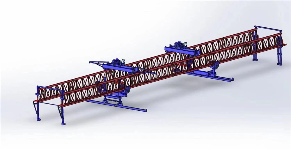
1. Main Girder (Bridge Frame)
Description: The long horizontal beam that spans across bridge piers.
Function: Carries the precast bridge segments and transfers loads to the support carriages.
Notes: Usually made of high-strength steel; must withstand bending moments from heavy segments (up to 150 tons).
2. Lifting Mechanism
Components: Hydraulic jacks, hoists, winches, or cranes mounted on the girder.
Function: Lifts the precast bridge segments from the transport vehicle to the girder, then positions them accurately on the piers.
Notes: Precision is critical; these mechanisms must handle sudden load shifts without destabilizing the girder.
3. Self-Balancing System
Components: Hydraulic cylinders, sensors, load cells, and automatic control valves.
Function: Maintains balance while lifting and moving segments, adjusting for asymmetrical loads.
How It Works:
Sensors detect tilt or uneven load.
Hydraulic jacks extend or retract to counteract imbalance.
Importance: Prevents tipping, especially on uneven piers or during long-span launches.
4. Launching Mechanism
Components: Hydraulic pushers, sliding rails, or gantry rollers.
Function: Moves the girder forward to the next span after placing a segment.
Notes: Enables incremental construction, so the bridge can be built without temporary scaffolding.
5. Support Carriages / Bogies
Components: Wheeled or tracked units under each end (sometimes multiple per girder).
Function: Transfers the weight of the girder and segment to the piers; allows smooth movement along the bridge alignment.
Notes: Often adjustable to accommodate different pier heights and bridge curvature.
6. Control Cabin / Operator Panel
Components: Cabin with hydraulic controls, joystick systems, display screens for load/tilt.
Function: Allows operators to manage lifting, balancing, and launching safely.
Modern Feature: Some systems have semi-automated or fully automated control with feedback from sensors.
7. Auxiliary Systems
Power Supply: Diesel engine or electric motors for hydraulics.
Safety Systems: Load limiters, tilt alarms, emergency brakes.
Walkways & Platforms: For operators to access segments and maintain equipment.
In short: The girder is a self-contained mobile construction platform with lifting, balancing, and launching capabilities. Each component works together to move massive bridge segments safely and efficiently.

Sketch

Advantages
1. Handles Heavy Loads
Can lift and place precast segments up to 150 tons, making it suitable for long-span or high-capacity bridges.
Reduces the need for multiple smaller cranes or supports.
2. Self-Balancing Capability
Automatically adjusts for uneven loads, preventing tipping or uneven stresses.
Enhances safety for workers and equipment.
Particularly useful for bridges with asymmetrical spans or variable segment weights.
3. Reduces Need for Temporary Supports
Traditional bridge construction often requires scaffolding or falsework under the span.
The girder supports itself, eliminating costly and time-consuming temporary structures.
Allows construction over rivers, highways, or deep valleys without obstructing traffic.
4. Efficient Segment Placement
Precast segments can be lifted and placed quickly and accurately.
Reduces construction time, often allowing continuous launching of multiple segments.
5. Works on Difficult Terrain
Can operate over uneven or inaccessible sites where conventional cranes can't reach.
Tracks or bogies distribute load evenly on piers or temporary supports.
6. Safety Improvements
Built-in hydraulic and electronic balancing systems prevent accidents.
Operators can control lifting and launching from a safe distance.
Load sensors and alarms alert if something is off balance.
7. Cost and Labor Efficiency
Fewer cranes and temporary structures mean lower overall construction costs.
Reduces manpower requirements, since the system automates balancing and segment placement.
8. Adaptability
Can be used for curved, straight, or variable-span bridges.
Adjustable supports and launch mechanisms make it versatile for different bridge designs.
✅ Summary:
A 150-ton self-balancing bridge launching girder is heavy-duty, self-stabilizing, and highly efficient, making it perfect for modern large-span bridges, especially where speed, safety, and minimal site disruption are priorities.

Application
1. Highway and Road Bridges
Ideal for precast segmental highway bridges, especially over busy roads or urban areas where space for cranes is limited.
Reduces traffic disruption, since segments are placed from above without needing temporary supports on the road.
2. Railway Bridges
Suitable for heavy railway bridges, including high-speed rail, where precision and heavy-load capacity are critical.
Can place long-span segments over tracks without interrupting train operations.
3. River and Canal Crossings
Can launch segments over water bodies, avoiding the need for expensive temporary piers or scaffolding in the water.
Useful in environmentally sensitive areas, minimizing impact on water flow and aquatic life.
4. Urban or Congested Areas
Works in tight spaces where cranes cannot operate or scaffolding would block streets.
Self-balancing design allows installation in limited right-of-way locations.
5. Long-Span or Curved Bridges
Can handle complex geometries, such as curved alignments or variable span lengths.
Balancing system ensures stable segment placement even on curved or uneven bridge sections.
6. Viaducts and Elevated Expressways
Often used for multi-span elevated highways or flyovers, where continuous launching is more efficient than conventional cranes.
Reduces construction time significantly in large-scale projects.
7. Remote or Inaccessible Locations
Can operate in areas without road access or crane availability, such as mountainous terrain or dense forests.
Tracks or bogies distribute load safely on piers in rough terrain.

Production Procedure
1. Design and Planning
Engineering Design:
Structural engineers design the girder based on load capacity (150 tons), span length, and bridge type.
Includes main beam dimensions, self-balancing system, lifting mechanism, and support carriages.
Simulation & Analysis:
Finite Element Analysis (FEA) checks stress, deflection, and stability under full load.
Ensures safety margins and proper balance during operation.
Material Selection:
High-strength steel for main girder and support frames.
Heavy-duty hydraulics for lifting and balancing systems.
2. Material Preparation
Steel Plates & Sections: Cut and prepared according to design specifications.
Hydraulic Components: Cylinders, pumps, and sensors are procured from certified manufacturers.
Electrical Systems: Wiring, control panels, and sensors are prepared for integration.
3. Fabrication of Components
Main Girder Fabrication:
Steel plates are welded into the primary beam structure.
Reinforcement plates and stiffeners are added to prevent bending under load.
Support Carriages/Bogies:
Welded and machined with wheels/tracks.
Bearings and hydraulic lifting jacks installed.
Lifting & Balancing Mechanisms:
Hydraulic cylinders, hoists, and counterweight mechanisms assembled.
Sensors and actuators mounted for automatic self-balancing.
4. Sub-Assembly
Major components like main girder, carriages, and hydraulic systems are partially assembled in the factory.
Test fittings performed to ensure alignment and structural integrity.
5. Final Assembly
All sub-assemblies brought together on a large assembly platform.
Hydraulic, electrical, and mechanical systems are fully integrated.
Control cabin and operator panels installed.
6. Testing and Calibration
Load Testing: Simulated segment weights applied to ensure the girder supports 150 tons safely.
Self-Balancing Test: Hydraulics and sensors tested for tilt correction and automatic balance.
Movement & Launching Test: Girder is moved along mock-up tracks to verify launching mechanism.
Safety Checks: Emergency brakes, alarms, and redundant systems checked.
7. Painting and Corrosion Protection
Steel surfaces are sandblasted and coated with anti-corrosion paint.
Ensures durability in outdoor construction sites.
8. Shipping & Site Installation
Girder may be disassembled into transportable sections for road or rail delivery.
Reassembled on-site by engineers and technicians.
Final tests performed before live bridge segment installation.


Workshop View
The company has installed an intelligent equipment management platform, and has installed 310 sets (sets) of handling and welding robots. After the completion of the plan, there will be more than 500 sets (sets), and the equipment networking rate will reach 95%. 32 welding lines have been put into use, 50 are planned to be installed, and the automation rate of the entire product line has reached 85%.


Hot Tags: 150ton self-balancing bridge launching girder, China 150ton self-balancing bridge launching girder manufacturers, suppliers, factory
You Might Also Like


Send Inquiry