







Rubber Tired Gantry For Container Yard
Product Introduction
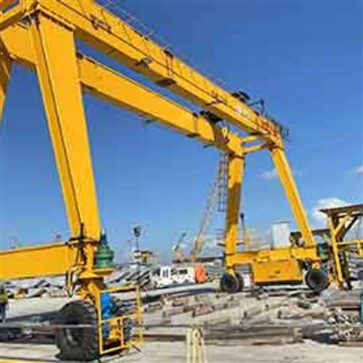
RTG stands for Rubber-Tyred Gantry Crane-often referred to simply as a "rubber-tyred crane" at the terminal. Capable of moving flexibly across the yard on rubber tires, it serves as the core equipment for stacking, loading, unloading, and transporting containers.
If a container terminal is likened to a massive logistics hub, then the RTG is the "strongman" that shuttles back and forth across the yard, handling the movement and stacking of containers.
Core Features
Exceptional Mobility
The most significant advantage of an RTG is its flexibility. It travels on rubber tires and does not require fixed tracks like an RMG (Rail-Mounted Gantry Crane). This allows it to freely move between yard blocks, operate across different areas, and even perform 0-90° steering, making it ideal for dynamic terminal layouts.
Main Structure
An RTG consists of four main components:
Metal Structure – The gantry frame and main girders supporting the load.
Traveling Mechanism – Rubber-tired wheels and drive units for mobility.
Hoisting Mechanism – Motors, gearboxes, drums, wire ropes, and the spreader.
Spreader System – Telescopic spreader for handling 20ft, 40ft, and 45ft containers.
Green Technology Trends
Due to stricter environmental regulations and rising fuel costs, the RTG market is rapidly shifting toward greener power solutions:
Full Electric / Lithium Battery: Powered by grid electricity or large lithium battery packs. Zero emissions. Regenerative braking recovers energy during lowering.
Hybrid Systems: Combine a diesel generator with a battery bank. Can recover lowering energy and achieve 40-60% fuel savings.
Variable Speed Diesel: Automatically adjusts engine speed based on load. Saves over 20% fuel compared to fixed-speed engines.
Intelligent Upgrades
Modern RTGs are no longer simple "container movers." New generation Automated RTGs (ARTGs) feature:
Remote Control: Operators manage multiple cranes from a central control room.
Auto-Steering & Positioning: DGPS and magnetic guidance systems for precise, automated movement.
Anti-Sway & Auto-Landing: Advanced sensors and software for safe, efficient automatic container pickup and placement.
Key Specifications
RTG specifications have become largely standardized, with some customization available.
| Parameter | Typical Range / Standard Configuration | Notes |
|---|---|---|
| Lifting Capacity (under spreader) | Mainstream: 35-41 tons Range: 30-70 tons |
41 tons is becoming the new industry standard for most terminals. |
| Span | Standard: 23.47 meters Alternative: 26 meters or customized |
23.47m covers "6 container rows + 1 truck lane". |
| Lifting Height / Stacking Capacity | Usually: 3-6 tiers (12.2-18.2 meters) | New generation models typically stack "5 high, 6 over" (1-over-5). |
| Operating Speeds | Hoisting: 13-23 m/min (full load) Crane Travel: 20-90 m/min (full load) |
Speeds vary depending on model and drive system. |
| Power Options | Diesel, Hybrid, Battery-Electric, Grid-Electric | Hybrid and electric models are the clear trend. |

Pictures & Components
An RTG is a complex electromechanical system composed of four main systems working together: Metal Structure, Working Mechanisms, Power & Control System, and Auxiliary & Safety Systems.
1. Metal Structure (The Skeleton)
This is the main framework that supports all loads and provides mounting bases for all other components.
Main Girders are the primary load-bearing beams, typically built as box-type structures with rails on top for the trolley to travel along. Door Legs (Outriggers) support the main girders, and the space between them is often used to house the electrical room and power house. At the bottom, Bottom Beams or End Carriages connect the legs and are attached to the travel mechanism via pin shafts.

2. Working Mechanisms (The Movements)
These are the systems that actually perform the container handling operations.
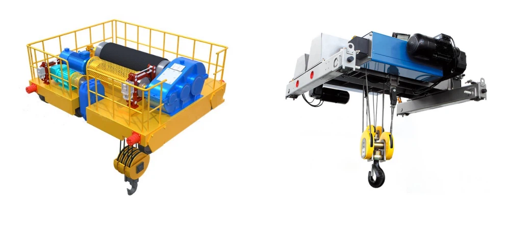
The Hoisting Mechanism is responsible for vertical lifting and lowering. It includes the hoist motor which provides lifting power, a reducer or gearbox that reduces speed and increases torque, and drums and wire ropes wound around the drums to raise and lower the spreader. A load sensor monitors weight to prevent overloading, and height limiters restrict the upper and lower travel of the spreader.
The Trolley Travel Mechanism moves the spreader and hoist laterally along the main girders. It consists of a travel motor and reducer for power, a trolley frame that supports the hoist and travels on rails, and optional positioning systems like laser distance measurement or encoders for high-precision positioning down to ±10mm.
The Crane Travel Mechanism (Wheel System) drives the entire RTG across the yard. Rubber tires provide mobility and cushioning, typically in 4-wheel or 8-wheel configurations. Independent drive motors for each wheel set enable various steering modes, including straight, diagonal, and 0-90° in-situ turning.
The Container Spreader is the specialized attachment that directly grips containers. Its telescopic mechanism extends or retracts to fit 20ft, 40ft, or 45ft containers. Twistlocks are locking pins that engage the container's corner castings, available in manual, semi-auto, or fully automatic versions. A rotator allows ±5° hydraulic rotation for alignment, integrated with the anti-sway system.


3. Power & Control System (The Energy & Brain)
The Power System provides energy for all RTG operations. Traditional models use a diesel generator, but modern trends favor hybrid systems combining diesel with batteries to recover energy from lowering, or full electric systems using lithium batteries or grid power via cable reel for zero emissions.
 |
 |
 |
The Electrical Control System coordinates all mechanisms. The PLC controller serves as the core, processing signals and executing programs to coordinate all movements. Variable Frequency Drives (VFDs) enable precise speed control for hoisting, trolley, and travel motors. The HMI or Control Console in the cabin provides the operator interface, displaying system status and enabling control, while the communication network connects the PLC with remote control systems and automation infrastructure.
 |
 |
 |
4. Auxiliary & Safety Systems
The Operator Cabin is the control center, typically suspended below the trolley. It features an ergonomic console with joysticks and touchscreen, an HVAC system for operator comfort, and safety glass with anti-glare properties for optimal visibility.

Safety Protection Systems provide multi-layer protection. Overload protection prevents lifting loads exceeding rated capacity. Anti-collision systems use laser or radar sensors to prevent collision with other equipment or structures. Wind clamps secure the RTG during high winds, while an anemometer monitors wind speed and triggers alarms or auto-secure actions. Limit switches provide mechanical/electrical limits for hoist height and travel.
.

Summary of Systems
The Metal Structure consists of Main Girders, Door Legs, and Bottom Beams.
The Hoisting Mechanism includes the Hoist Motor, Gearbox, Drums, Wire Ropes, and Load Sensor.
The Trolley Mechanism comprises the Travel Motor, Trolley Frame, and Positioning System.
The Travel Mechanism consists of Rubber Tires, Wheel Motors, and the Steering System.
The Spreader includes the Telescopic Frame, Twistlocks, and Anti-Sway System.
The Power & Control system covers Diesel/Hybrid/Electric Power, PLC, VFDs, and HMI.
The Auxiliary systems include the Operator Cabin, Overload Protection, and Anti-Collision features.

Sketch

Main technical

Advantages
Key Advantages of RTG
Unmatched Mobility & Flexibility
The most significant advantage of an RTG is its ability to move freely without fixed tracks. Rubber tires allow it to transfer between yard blocks, operate across different areas, and perform 0-90° steering. This flexibility makes it ideal for terminals with dynamic layouts or multi-purpose operations.
Lower Initial Investment
Compared to RMG (Rail-Mounted Gantry Crane), RTG requires no expensive track infrastructure or extensive ground preparation. The initial capital investment is significantly lower, making it accessible for medium-sized terminals and ports with budget constraints.
Rapid Deployment
RTG can be delivered and put into operation quickly since there is no need for rail installation or complex civil works. This is particularly valuable for terminals needing to expand capacity rapidly.
Adaptability to Yard Changes
As container terminals evolve, yard layouts often change. RTGs can be easily relocated to new areas without the costly and time-consuming track modifications required for RMGs.
Multi-Purpose Capability
Beyond container stacking, RTGs can be equipped with various attachments for handling different cargo types, including bulk materials and heavy machinery, adding operational versatility.
Proven Reliability
RTGs have been the workhorse of container terminals for decades. Their robust design and mature technology ensure high reliability and uptime in demanding 24/7 operations.
Application:
Port Container Terminals
RTGs are extensively used in port yards for stacking, retrieving, and transferring containers between trucks, rail wagons, and storage blocks. They handle the high-volume, continuous flow of containers in busy seaports.
Rail Intermodal Yards
At rail terminals, RTGs efficiently transfer containers between trains and storage areas or trucks. Their mobility allows them to serve multiple rail tracks without the need for complex track switching systems.
Multi-Purpose Terminals
Facilities handling both containers and other cargo types benefit from RTG flexibility. They can be used for container stacking as well as heavy-lift operations with specialized attachments.
Inland Container Depots
Inland logistics hubs and bonded warehouses use RTGs for container storage, consolidation, and distribution, providing efficient cargo handling away from seaports.
Large Logistics Parks
RTGs are also deployed in sprawling logistics centers that require flexible, high-capacity container handling across extensive storage areas.
Crane production procedure
1. Design and Engineering Phase
This is the foundation of the entire process. The design phase determines the crane's type, key parameters (lifting capacity, span, lifting height), and the details of its mechanical structure, electrical system, and control systems.
Key Activities:
Customization: Manufacturers work with clients to tailor the crane to specific operational needs, including power options (diesel, hybrid, or fully electric).
Structural Analysis: Engineers perform meticulous calculations and simulations to ensure the structural integrity of the crane, analyzing load-bearing capacities, stress points, and overall stability.
Compliance: The design must adhere to international standards such as ISO, FEM, and OSHA to guarantee safety and performance.
2. Material Selection and Fabrication
With the design finalized, the focus shifts to sourcing and preparing the raw materials.
Key Activities:
Steel Selection: High-strength steels, such as Q235 and Q355, are commonly used for the main structural components due to their yield strength and durability.
Surface Treatment: Materials are often prepared with anti-corrosion treatments to withstand harsh working environments.
Precision Manufacturing: Advanced techniques like CNC machining, robotic welding, and laser cutting are employed to achieve high precision and consistency in creating individual parts.
3. Component Manufacturing
This stage involves the creation of the main sub-assemblies. A key modern approach is modular manufacturing, where large components like the main girders, door legs, and bottom beams are fabricated as separate, manageable modules. This approach simplifies later transportation and on-site assembly.
Critical Structural Components:
Main Girders: These are typically box-type structures, manufactured with high precision and equipped with rails on top for the trolley to travel along.
Door Legs (Outriggers): These support the main girders. The space between them often houses the electrical and power rooms.
Bottom Beams / End Carriages: These connect the legs and are attached to the travel mechanism.
Bolted Joints: Large steel structures are often connected using bolted joints with high-strength bolts (e.g., 10.9 grade). The flatness and precision of these joints are critical for structural stability and may require careful welding and manufacturing techniques.
4. Structural Assembly
This is where the individual components are brought together to form the crane's structure. This can happen at the factory or, more commonly for large RTGs, at the customer's site.
Typical On-Site Assembly Steps:
Site Preparation: The site is surveyed, leveled, and prepared with necessary foundations (for rail-mounted RTGs) or compacted ground (for tire-mounted RTGs).
Positioning and Ground Beams: The positions for the crane's wheels or rail tracks are marked, and ground beams are placed in their designated locations.
Assembling Door Legs: The supporting legs are mounted and secured onto the ground beams.
Main Girder Erection: A large mobile crane (often 200-300 tons) is used to lift and position the main girders onto the door legs. For double-girder RTGs, two mobile cranes may be required for synchronized lifting.
Gantry Closure: The top of the door legs is aligned and bolted to the main girders to form the complete gantry frame. The structure is then precisely aligned using instruments like theodolites and levels.
5. System Integration and Commissioning
Once the mechanical structure is erected, the focus shifts to installing and testing the electrical, control, and mechanical systems. The commissioning phase is a systematic and critical process that occurs after erection to confirm the crane's safety, quality, and performance before it is handed over to the customer.
Key Activities in Commissioning:
Install Subsystems: Install the hoist trolley, operator cabin, container spreader, and all electrical components onto the gantry structure.
Hoist Setup & Calibration: Set up the hoist mechanism and calibrate the load cells to ensure accurate weight measurement.
Positioning Calibration: Calibrate the trolley position and limits, and set up the skew system for the spreader.
Spreader Function Test: Test the spreader's telescoping mechanism, flippers, and twistlocks to ensure they function correctly.
Interlocks and Safety Tests: A series of interlocks and safety tests are mandatory. This includes testing emergency stops, hazard plates, warning horns, hoist safety limits, trolley and gantry travel limits, and other protective functions.
Load and Performance Tests: Perform tests under load, including verifying working speeds and accelerations, and conducting an endurance test at 100% of the Safe Working Load (S.W.L.).
6. Quality Assurance and Testing
Throughout the entire production procedure, rigorous quality checks are performed. This includes non-destructive testing (NDT) methods like ultrasonic testing and radiographic testing to check for internal flaws in critical welds and materials. A comprehensive pre-delivery inspection is conducted to verify all systems and address any issues before the crane leaves the factory.

Workshop view
Material Inspection
Quality Inspection: Strict quality inspection is carried out on the purchased raw materials to ensure that they meet the design requirements and national standards.
Material Storage: Qualified materials are stored according to classification to prevent corrosion or damage.
Cutting and Forming
Steel Cutting: Use plasma cutting, laser cutting or flame cutting and other technologies to cut the steel according to the size of the design drawing.
Forming Processing: Form the steel plate through bending, rolling, welding and other processes to manufacture the main beam, end beam and other structural parts.
Welding
Component Welding: The cut and formed steel parts are welded into the main structures such as the main beam, end beam and trolley. The welding process needs to be strictly controlled to ensure the structural strength and welding quality.
Weld Inspection: Use non-destructive testing technology (such as ultrasonic testing, radiographic testing) to inspect the welds to ensure that there are no cracks or other defects.
Machining
Precision Machining: Precision machining is performed on the key components of the crane, such as wheel sets, bearing seats, pulleys, etc., to ensure their dimensional accuracy and surface quality.
Assembly of the whole machine
General assembly: On the basis of pre-assembly, the overall assembly of the crane is carried out, including the final installation of the main beam, end beam, lifting mechanism, walking mechanism, etc.
Commissioning and testing
Under dynamic conditions, the operating performance of the crane is tested, including the testing of lifting, walking, steering and other functions. The overall size of the assembled bridge crane is checked to ensure that all dimensions meet the design requirements.
Spraying and anti-corrosion treatment
Surface treatment Rust removal: Rust removal on the surface of the crane, common methods include sandblasting, pickling, etc. Primer spraying: Spray anti-corrosion primer on the treated surface to prevent metal oxidation and corrosion. Topcoat spraying Color spraying: Spray topcoat according to customer requirements or industry standards to give the crane a protective and decorative effect. Marking: After spraying, mark the crane's identification information in accordance with the specifications, such as model, rated load, etc.
Factory and installation
Packaging and transportation
Packaging protection: Protectively package the key components of the crane to prevent damage during transportation. Transportation arrangement: According to the equipment size and transportation conditions, select a suitable transportation method to transport the crane to the customer's site.
Acceptance and delivery
Customer acceptance
On-site acceptance: The customer conducts on-site acceptance of the crane according to the contract requirements and technical specifications to check the performance and quality of the equipment.
Problem rectification: If any problems are found, the manufacturer needs to rectify them in time to ensure that the equipment fully meets the customer's requirements. Delivery and use Operation training: The manufacturer usually trains the customer's operators to ensure that they can operate the crane correctly and safely.


Hot Tags: rubber tired gantry for container yard, China rubber tired gantry for container yard manufacturers, suppliers, factory
You Might Also Like



Send Inquiry