







40 Ton Rail Mounted Gantry Crane
Product Introduction
What is a Rail-Mounted Gantry Crane (RMG)?
A Rail-Mounted Gantry Crane (RMG) is a large, heavy-duty container handling crane that operates on fixed rails running along the ground. It is a cornerstone of modern, high-throughput port terminals and intermodal rail yards, designed for the efficient stacking, loading, and unloading of ISO shipping containers in 24/7 operations .
Unlike Rubber-Tired Gantry (RTG) cranes, RMGs travel on a dedicated track system, which provides superior stability, precision, and the capacity for high levels of automation .
Key Advantages and Features
High Efficiency and Stability: Operating on fixed rails, the RMG offers high positioning accuracy (up to ±50mm) and high operating speeds (trolley speeds up to 300m/min), resulting in exceptional operational efficiency. Compared to RTGs, it boasts superior stacking capabilities, enabling "1-over-7" or even higher stacking densities.
Economical and Eco-friendly: Powered by grid electricity, the system features low energy consumption and zero emissions, with operating costs significantly lower than those of diesel-powered RTGs. Some advanced models are equipped with energy feedback technology for further energy savings.
Intelligent Automation: The electrical system utilizes PLC control and AC variable-frequency drive technology, ensuring flexible control and high precision. The RMG is the ideal model for integration with Terminal Operating Systems (TOS) to achieve fully automated, unmanned operations (ARMG) and serves as core equipment for modern smart port development.
Safety and Reliability: Equipped with a comprehensive dual-axis anti-sway system, multiple safety protection devices (anti-collision, high-wind alarms, anti-lift protection, etc.), and an intelligent CMS monitoring system, it ensures the safety of personnel, equipment, and cargo.
RMG vs. RTG
| Comparison Aspect | RMG (Rail-Mounted Gantry Crane) | RTG (Rubber-Tired Gantry Crane) |
|---|---|---|
| Mobility & Maneuverability | Operates on fixed rails. Low mobility – cannot transfer between yards. | Travels on rubber tires. Can steer 90° and move freely between yards – excellent mobility. |
| Power Source & Energy Cost | Grid power supply – low energy consumption, quiet, zero emissions. Can recover regenerative energy during lowering. | Traditional models use diesel generators – high fuel consumption, noisy, with emissions. Hybrid or fully electric options are increasingly available. |
| Operational Capacity & Efficiency | Large span (up to 16 container rows), high stacking density (7+ tiers), high positioning accuracy, excellent efficiency. | Span typically 6-8 container rows, stacking height slightly lower (5-6 tiers). Efficiency is more dependent on operator skill. |
| Automation Potential | Extremely high. Ideal for fully automated unmanned operation (ARMG/ASC), seamlessly integrating with Terminal Operating Systems (TOS). | Lower. Automation and intelligent control systems are more complex and less commonly deployed. |
| Cost & Investment | High initial infrastructure investment (requires rails, power supply systems). But long-term operating and maintenance costs are lower. | Lower initial investment (no rails required). However, fuel and maintenance costs are higher. Grid-connected electric RTGs can reduce operating costs. |
| Primary Application | Large seaports, rail transfer hubs. Suitable for high-volume terminals with stable layouts and a focus on long-term efficiency. | Medium/small ports, multi-purpose yards. Suitable for terminals with moderate throughput and flexible, changing layouts. |
Core Parameter Range
| Parameter | Typical Range | Notes |
|---|---|---|
| Lifting Capacity | 30.5 – 65 tons (standard) Customizable up to 100+ tons |
Capacity under the spreader. Suitable for 20ft, 40ft, and 45ft ISO containers. |
| Span | 25m – 50m+ | Typically covers 6+ container rows + one truck lane. Custom spans from manufacturers like Liebherr can exceed 70 meters. |
| Lifting Height | 15m – 25m+ | Typically stacks 5 to 6 tiers (1-over-5 or 1-over-6). Maximum height can reach 8 tiers (approx. 26.9 meters). |
| Duty Class | A6 – A8 | Indicates suitability for high-intensity, continuous, 24/7 terminal operations. |

Pictures & Components
A Rail-Mounted Gantry Crane (RMG) is a complex electromechanical system consisting of four main systems working together: Metal Structure, Hoisting & Traveling Mechanisms, Electrical & Control Systems, and Auxiliary & Safety Devices. Below is a breakdown of each core component.
1. Metal Structure (The Skeleton)
This is the main framework that carries all loads and weight.
Main Girder – Typically a box-type or truss structure. This is the core component that supports the container load, with spans reaching 40-60 meters.
 .
Outrigger / Door Leg – The supporting structure connecting the main girder to the traveling mechanism. Often designed as a combination of a rigid leg and a flexible leg, with the flexible leg hinged to accommodate track unevenness.
Traveling Cart – Located at the bottom of the legs. This is the mechanism that drives the RMG along the rails, consisting of motors, gearboxes, and wheel sets.
2. Hoisting & Traveling Mechanisms (The Motions)
These mechanisms enable the crane's 3D movements (vertical, horizontal, and longitudinal).
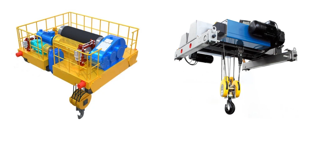
Hoisting Mechanism – Composed of motor, gearbox, drum, wire ropes, and spreader. This is the executive unit for vertical lifting, often integrated with anti-sway functions.


Trolley Travel Mechanism – Moves the spreader horizontally along the main girder for precise container positioning.
Crane Travel Mechanism – Drives the entire RMG longitudinally along the ground tracks, reaching speeds of 90-130 m/min.
 |
 |
 |
3. Electrical & Control System (The Brain & Power)
This is the "brain" and power source of the RMG.
Control System – Integrates PLC controllers and Variable Frequency Drives (VFD) to coordinate all mechanisms. This is the core of automation and intelligence.
 |
 |
 |
Power Supply System – Connects to the grid via cable reels or conductor bars. Typically housed in an independent Electrical House (E-House) .
Operator Cabin – The control center, equipped with an intuitive human-machine interface (HMI).

4. Auxiliary & Safety Devices (The Protection)
These ensure efficient and safe operation.
Container Spreader – Connects to container corner castings via hydraulic twistlocks. Usually telescopic to handle various container sizes ( 20ft, 40ft, and 45ft ).
.
Active Load Control (ALC) / Anti-Sway System – Actively suppresses swing of the spreader and container. This is a core function for efficient, precise positioning, especially essential for automated operations.
Safety Protection Systems – Include limit switches, overload limiters, anti-collision systems, wind clamping devices, anemometers, and more. Multiple layers ensure safety for personnel and equipment.

These components work together to enable efficient and precise container handling. The metal structure – particularly the rigid/flexible leg combination – provides a stable foundation. The control system acts as the commander, coordinating the hoisting, trolley, and crane travel mechanisms. Finally, the telescopic spreader and anti-sway system ensure accurate pick-up and placement of containers.

Sketch

Main technical

Advantages
Unmatched Efficiency & Precision
RMGs deliver extremely high positioning accuracy (often within a few millimeters) due to their fixed rail paths. This precision, combined with higher travel speeds than rubber-tired alternatives, enables faster, more consistent container handling cycles.
High-Density Storage Capacity
Their structural design allows for larger spans (easily covering over 6 rows of containers) and higher stacking (often reaching 7 or more tiers). This maximizes yard space utilization, a critical advantage in land-scarce port areas.
Lower Operating Costs
Powered directly by grid electricity, RMGs are significantly more energy-efficient than diesel-powered RTGs. They have lower fuel, maintenance, and engine overhaul costs, leading to substantial savings over their long service life.
Superior Automation Readiness
RMGs are the ideal platform for automation. Their deterministic rail-based movement simplifies integration with Terminal Operating Systems (TOS) , enabling semi- and fully automated operations (ARMG/ASC) with reduced labor costs and improved safety.
Exceptional Reliability
Designed for continuous, heavy-duty use, RMGs are built for a long operational lifespan. The fixed rail system reduces wear on travel mechanisms, contributing to their reputation for high reliability and uptime.
Application:
Large Seaport Container Terminals
Used for dense, high-speed stacking, retrieval, and truck/rail loading in the yard, directly supporting rapid vessel turnaround.
Intermodal Rail and Inland Terminals
Acts as a critical link in the logistics chain for rapidly loading and unloading entire trains, supporting high-volume, multi-modal cargo transfer.
Container Freight Stations (CFS) & Logistics Parks
Manages large-scale container storage, consolidation, and distribution at major inland logistics hubs.
Crane production procedure
1. Engineering Design & Planning
Load calculation (SWL, impact, wind, seismic)
Span, lifting height, and duty class determination (ISO / FEM / CMAA)
Structural design of box girders and A-type legs
Selection of hoisting, traveling, and electrical components
Preparation of:
General arrangement drawings
Fabrication drawings
Electrical schematics
Design review and customer approval
2. Raw Material Procurement & Inspection
Procurement of structural steel plates and profiles
Inspection of:
Material grade and thickness
Mill test certificates (MTC)
Storage under controlled conditions to prevent corrosion
3. Steel Cutting & Preparation
CNC flame cutting / plasma cutting of steel plates
Edge preparation for welding
Shot blasting for surface cleanliness (Sa 2.5 standard)
Marking and identification of components
4. Box Girder Fabrication
Assembly of top plate, bottom plate, and side plates
Automatic submerged arc welding (SAW)
Camber control and deflection correction
Internal stiffener installation
Non-destructive testing (UT, MT)
5. A-Type Leg Fabrication
Fabrication of rigid and hinged legs (box structure)
Welding of bracings and stiffeners
Machining of connection plates
Dimensional inspection and NDT testing
6. End Carriage Manufacturing
Fabrication of end carriage frames
Installation of:
Wheels
Bearings
Axles
Alignment and load distribution checks
7. Machining & Assembly of Mechanical Components
Machining of:
Wheel seats
Shaft holes
Connection surfaces
Assembly of:
Hoist unit
Trolley frame
Gearboxes and couplings
8. Surface Treatment & Painting
Final shot blasting of all structural parts
Application of:
Primer coat
Intermediate coat
Finish coat
Paint thickness inspection (DFT)
Corrosion protection per environment class
9. Electrical System Installation
Installation of motors, brakes, and limit switches
Wiring of control panels and junction boxes
Installation of:
Cable festoon or conductor bars
Control cabin or remote control system
Electrical continuity and insulation testing
10. Pre-Assembly & Factory Trial
Trial assembly of main girders, legs, and end carriages
Alignment and dimensional verification
No-load functional testing:
Hoisting
Trolley travel
Crane travel
11. Load Testing & Quality Inspection
Static load test (125% of rated load)
Dynamic load test (110% of rated load)
Safety device testing
Final inspection per standards
12. Dismantling, Packing & Dispatch
Dismantling into transportable sections
Protective packing for long-distance shipment
Documentation preparation:
Test certificates
Quality reports
Operation & maintenance manuals
13. Site Installation & Commissioning (Optional)
Rail alignment verification
Crane erection and bolting
Electrical connection and system calibration
Final load testing and handover

Workshop view
Material Inspection
Quality Inspection: Strict quality inspection is carried out on the purchased raw materials to ensure that they meet the design requirements and national standards.
Material Storage: Qualified materials are stored according to classification to prevent corrosion or damage.
Cutting and Forming
Steel Cutting: Use plasma cutting, laser cutting or flame cutting and other technologies to cut the steel according to the size of the design drawing.
Forming Processing: Form the steel plate through bending, rolling, welding and other processes to manufacture the main beam, end beam and other structural parts.
Welding
Component Welding: The cut and formed steel parts are welded into the main structures such as the main beam, end beam and trolley. The welding process needs to be strictly controlled to ensure the structural strength and welding quality.
Weld Inspection: Use non-destructive testing technology (such as ultrasonic testing, radiographic testing) to inspect the welds to ensure that there are no cracks or other defects.
Machining
Precision Machining: Precision machining is performed on the key components of the crane, such as wheel sets, bearing seats, pulleys, etc., to ensure their dimensional accuracy and surface quality.
Assembly of the whole machine
General assembly: On the basis of pre-assembly, the overall assembly of the crane is carried out, including the final installation of the main beam, end beam, lifting mechanism, walking mechanism, etc.
Commissioning and testing
Under dynamic conditions, the operating performance of the crane is tested, including the testing of lifting, walking, steering and other functions. The overall size of the assembled bridge crane is checked to ensure that all dimensions meet the design requirements.
Spraying and anti-corrosion treatment
Surface treatment Rust removal: Rust removal on the surface of the crane, common methods include sandblasting, pickling, etc. Primer spraying: Spray anti-corrosion primer on the treated surface to prevent metal oxidation and corrosion. Topcoat spraying Color spraying: Spray topcoat according to customer requirements or industry standards to give the crane a protective and decorative effect. Marking: After spraying, mark the crane's identification information in accordance with the specifications, such as model, rated load, etc.
Factory and installation
Packaging and transportation
Packaging protection: Protectively package the key components of the crane to prevent damage during transportation. Transportation arrangement: According to the equipment size and transportation conditions, select a suitable transportation method to transport the crane to the customer's site.
Acceptance and delivery
Customer acceptance
On-site acceptance: The customer conducts on-site acceptance of the crane according to the contract requirements and technical specifications to check the performance and quality of the equipment.
Problem rectification: If any problems are found, the manufacturer needs to rectify them in time to ensure that the equipment fully meets the customer's requirements. Delivery and use Operation training: The manufacturer usually trains the customer's operators to ensure that they can operate the crane correctly and safely.


Hot Tags: 40 ton rail mounted gantry crane, China 40 ton rail mounted gantry crane manufacturers, suppliers, factory
You Might Also Like


Send Inquiry