


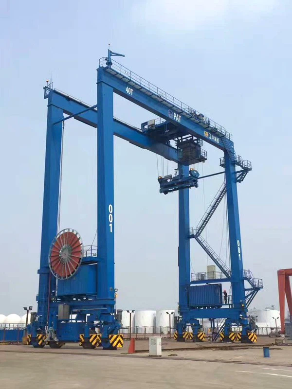
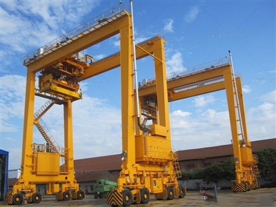
Mobile Travelling Rubber Tyre Gantry Crane
Products Description
Key Features of RTG Cranes:
Rubber-Tired Mobility – Moves on specially designed tires, allowing it to travel across the container yard without fixed rails.
High Lifting Capacity – Typically handles containers ranging from 30 to 50 tons, with some heavy-duty models capable of more.
Adjustable Span – Can span multiple container rows (commonly 4 to 8 rows wide) and stack containers up to 5 high.
Diesel-Electric or Electric Drive:
Diesel-electric RTGs – Powered by diesel generators, offering full mobility.
Electric RTGs (E-RTGs) – Use a cable reel or conductor bar system for reduced emissions and operating costs.
Automation & Remote Control – Modern RTGs may feature semi-automated or fully automated operation for improved efficiency.
Steering Systems – Can include 90° cross-yard steering, crab steering, or even 360° rotation for precise positioning.
Comparison with Other Gantry Cranes:
| Feature | RTG Crane | Rail-Mounted Gantry (RMG) | Ship-to-Shore (STS) Crane |
|---|---|---|---|
| Mobility | Rubber tires | Fixed rails | Fixed rails (on docks) |
| Flexibility | High | Low | Very Low |
| Typical Use | Yard stacking | Yard/rail operations | Loading/unloading ships |
Lifting Capacity 320 tons
Span (Width) 3 - 12 meters (adjustable)
Lifting Height 3 - 10 meters
Working Class A3-A5 (light to medium duty)
Hoisting Speed 0.5 - 8 m/min (variable)
Main Beam Type Single/double girder (box-type)
Power Supply 220V/380V 3-phase or manual
Control Mode Pendant control/wireless remote
Hoist Type Electric chain hoist/wire rope hoist
Travel Drive Manual push or motorized
Corrosion Protection Hot-dip galvanized or marine-grade paint
Wind Resistance Up to Beaufort scale 6 (for outdoor use)
Operating Temp -20°C to +50°C

Pictures & Componen
A Mobile Traveling Rubber Tyre Gantry Crane (RTG) consists of several key structural, mechanical, and electrical components that work together to ensure efficient container handling. Below is a breakdown of the major components:
1. Structural Components
A. Main Gantry Frame
The primary steel structure that spans the container stacks.
Includes legs, girders, and cross beams for stability.
Designed to withstand heavy loads and dynamic forces.

B. Boom (Lifting Arm)
Extends over the container stacks for lifting and moving containers.
May be fixed or telescopic, depending on the model.
C. End Carriages (Bogies)
Located at the base of each leg, housing the wheels, tires, and drive mechanisms.
Supports the crane's weight and allows movement.

2. Mobility & Drive Components
A. Rubber Tires
Heavy-duty, puncture-resistant tires (usually 8–16 tires in total).
Allow movement across the container yard without rails.
B. Travel Drive System
Electric or hydraulic motors power the wheels.
May include variable frequency drives (VFDs) for smooth acceleration/deceleration.

C. Steering System
90° cross steering (for sideways movement).
Crab steering (diagonal movement).
Some models feature 360° steering for precise positioning.
D. Braking System
Service brakes (for normal stopping).
Emergency brakes (for sudden stops).
Parking brakes (to prevent unintended movement).

3. Lifting & Hoisting Components
A. Hoist Mechanism
Electric or hydraulic winches with wire ropes or chains.
Lifts and lowers containers (typically 30–50 tons capacity).
B. Spreader (Container Lifter)
Attaches to containers using twist locks.
Can handle 20', 40', 45', and even twin-lift configurations.
May include weighing systems to measure load.
C. Trolley System
Moves horizontally along the gantry beam.
Allows precise positioning of the spreader over containers.

4. Power System
A. Diesel-Electric RTG
Diesel generator powers electric motors.
Common in areas without fixed power infrastructure.
B. Electric RTG (E-RTG)
Powered via cable reel, conductor bars, or battery.
More energy-efficient and eco-friendly.
C. Hybrid RTG
Combines diesel and battery power for reduced fuel consumption.

5. Control & Automation Systems
A. Operator Cabin
Located on the gantry for manual control.
Equipped with joysticks, cameras, and monitoring screens.
B. Remote Control System
Allows operators to control the RTG from the ground.
Uses radio or wireless communication.
C. Automated RTG (A-RTG)
Uses laser scanners, GPS, and AI for autonomous operation.
Reduces labor costs and improves efficiency.
D. Safety & Monitoring Systems
Anti-collision sensors (to avoid crashes with other equipment).
Load moment indicators (LMI) (prevents overloading).
Wind speed sensors (locks crane in high winds).

6. Ancillary Components
A. Outriggers / Stabilizers
Extendable legs for additional stability during lifting.
B. Lighting & Warning Systems
LED lights for night operations.
Alarms and beacons for safety.
C. Chassis & Suspension
Absorbs shocks and vibrations during travel.

SKETCH

Main technical

Advantages
1. High Mobility & Flexibility
No fixed rails required – Moves freely on rubber tires, allowing easy repositioning.
Ideal for congested yards – Can navigate around obstacles and other equipment.
2. Cost-Effective Yard Operations
Lower infrastructure costs compared to rail-mounted gantry cranes (RMGs).
Reduced ground preparation – No need for embedded rails or reinforced concrete tracks.
3. Efficient Container Stacking
Stacks containers 4–6 high, optimizing yard space.
Handles multiple container sizes (20', 40', 45', twin-lift, and even refrigerated containers).
4. Versatile Power Options
Diesel-electric RTGs – Suitable for remote areas without electrical infrastructure.
Electric RTGs (E-RTGs) – Eco-friendly, lower operating costs, and reduced noise.
Hybrid RTGs – Combine diesel and battery power for fuel savings.
5. Automation & Remote Operation
Semi-automated & fully automated RTGs improve efficiency and reduce labor costs.
Remote-controlled operation enhances safety by allowing ground-based control.
6. Easy Relocation
Can be moved to different yard sections or even other terminals if needed.
Application
1. Port Container Terminals
Stacking and retrieving containers in storage yards.
Transferring containers between trucks, trains, and ships.
2. Intermodal Freight Yards
Loading/unloading containers from trains to trucks (and vice versa).
Temporary storage in logistics hubs.
3. Depot & Warehouse Operations
Managing container inventories in freight stations.
Handling bulk cargo (when equipped with specialized spreaders).
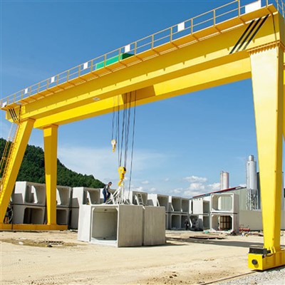
4. Construction & Industrial Sites
Heavy lifting of prefabricated structures or large materials.
Temporary yard management for project logistics.
5. Military & Emergency Logistics
Rapid deployment in disaster relief operations.
Mobile container handling in temporary bases.
Crane production process
The production process of a 200-ton mobile boat/marine lift crane involves several stages, from design and engineering to fabrication, assembly, and testing. Below is a detailed breakdown of the typical production process:
1. Design & Engineering
Conceptual Design: Engineers create initial sketches and 3D models based on load capacity (200 tons), reach, mobility, and environmental conditions (marine use).
Structural Analysis: Finite Element Analysis (FEA) ensures the crane can handle dynamic loads, wind, and wave forces.
Hydraulic & Electrical Systems: Design of hydraulic cylinders, winches, and control systems for smooth lifting operations.
Material Selection: High-strength steel (e.g., ASTM A514) for corrosion resistance in marine environments.
Regulatory Compliance: Meets standards like DNV-GL, ABS, or Lloyd's Register for marine cranes.
2. Material Procurement
Steel Plates & Beams: Sourced for the boom, chassis, and structural framework.
Hydraulic Components: Pumps, cylinders, hoses, and valves from certified suppliers.
Electrical Systems: Motors, sensors, and control panels (often waterproof for marine use).
Wire Ropes & Sheaves: High-grade steel cables for lifting.
3. Fabrication
A. Structural Fabrication
Cutting & Shaping: CNC plasma/laser cutting for precision parts.
Welding: Automated and manual welding (Submerged Arc Welding for thick sections).
Boom Construction: Lattice or telescopic design for strength and mobility.
Chassis & Outriggers: Reinforced for stability during lifts.
B. Hydraulic & Mechanical Assembly
Hydraulic System: Installation of pumps, cylinders, and hoses.
Winches & Drums: Mounted for lifting and lowering operations.
Slewing Mechanism: Allows 360° rotation (if applicable).
C. Electrical & Control Systems
Control Cabin: Waterproof operator station with joysticks/sensors.
Load Monitoring: Load cells and limit switches for safety.
Power Supply: Diesel engine or electric motor (marine-grade).
4. Assembly & Integration
Boom Installation: Mounted onto the chassis with pivot points.
Counterweights: Added for balance (if required).
Final Wiring & Plumbing: Connecting hydraulic and electrical systems.
Painting & Coating: Anti-corrosion paint (epoxy or zinc coatings).
5. Testing & Quality Control
Load Testing: Lifting 200 tons (+25% overload test, per standards).
Functional Tests: Checking hydraulic movements, rotation, and stability.
Environmental Tests: Salt spray tests for marine durability.
Safety Checks: Emergency stop systems, overload alarms.
6. Delivery & Commissioning
Transport: Disassembled for shipping or delivered as a mobile unit.
On-Site Assembly: Reassembled at the dock or shipyard.
Operator Training: Handling and safety protocols.

Workshop view:
The company has installed an intelligent equipment management platform, and has installed 310 sets (sets) of handling and welding robots. After the completion of the plan, there will be more than 500 sets (sets), and the equipment networking rate will reach 95%. 32 welding lines have been put into use, 50 are planned to be installed, and the automation rate of the entire product line has reached 85%.


Hot Tags: mobile travelling rubber tyre gantry crane, China mobile travelling rubber tyre gantry crane manufacturers, suppliers, factory
You Might Also Like


Send Inquiry