












80 Ton Double Girder Gantry Crane
Products Description
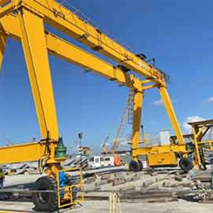
The 80-ton double girder gantry crane is a heavy-duty lifting solution designed for handling large and bulky loads in outdoor or semi-outdoor environments. Built with a robust double-girder structure, this gantry crane delivers excellent strength, stability, and lifting performance for demanding industrial applications.
Equipped with a hoisting mechanism mounted between or on top of the two girders, this crane ensures precise lifting and horizontal movement of loads. It operates on ground rails and is commonly used in shipyards, construction sites, steel yards, precast concrete plants, and container yards.
Key Features:
Lifting Capacity: 80 tons
Span Range: Customizable (typically 18–35 meters or more)
Lifting Height: Depending on the project needs (commonly 6–12 meters or higher)
Working Class: A5–A7 (medium to heavy-duty usage)
Control Mode: Cabin, remote control, or pendant control
Power Supply: Cable reel, festoon system, or busbar
Design Highlights:
Double Girder Design: Offers enhanced load-bearing capacity and rigidity.
High Wind Resistance: Suitable for outdoor use, with safety features for storm locking.
Precision Control: Smooth start/stop and accurate positioning of loads.
Customizable Structure: Available with cantilever arms, adjustable span, and special hooks as per specific operational needs.
Safety Systems: Equipped with overload protection, limit switches, emergency stop, and anti-collision devices.
Core Components:Bearing, Gear, Gearbox, Motor
Place of Origin:Henan, China
Warranty:1 Year
Weight (KG):2000 kg
Video outgoing-inspection:Provided
Machinery Test Report:Provided
Keywords:gantry crane
Color: Customized
Size: Customized
Design: computer optimization design
Safety: High flexible flat cable power
Application: construction industrial,workshop,warehouse
Working class: A3-A8
Certification: ISO,CE,BV,S GS,TUV
Power Source: 380~480V,customized

Pictures & Components
1.Main Girders
Type: Double box-shaped or truss-type steel beams
Function: Support the hoist/trolley and distribute the load evenly across the crane structure
Feature: High-strength welded design with minimal deflection

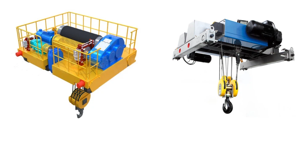
Trolley with Hoisting Mechanism
Type: Electric or hydraulic trolley system with motorized hoist
Hoist: Heavy-duty wire rope hoist or open winch hoisting mechanism
Function: Moves along the girders to lift and transport loads horizontally
3.End Carriages (Legs and Wheel Assemblies)
Structure: Two rigid legs (one or both may be A-frame or box-type)
Function: Support the main girders and allow the crane to move along ground rails
Wheels: Equipped with steel wheels for rail movement; may include guide wheels for stability

4.Crane Traveling Mechanism
Drive System: Motor + gearbox + brake
Drive Mode: Usually dual-drive for better balance and traction
Control: Variable frequency drive (VFD) for smooth acceleration and deceleration
5.Trolley travelling mechanism
1) Structural composition
Trolley frame: The frame is the main structural support of the trolley, providing the necessary rigidity and strength to bear the load.It is typically made of high-strength steel to ensure durability and resistance to deformation under heavy loads.
Wheel set: The wheels are often mounted on axles, and the bearings inside these wheels are designed for high load-bearing capacity and smooth operation.
Electric Drive Motor: The trolley's movement is powered by an electric motor, which drives the wheel system via a gearbox and a system of pulleys or chains.The motor is typically installed on the trolley frame and is connected to the wheels through a drive mechanism, allowing for both forward and backward motion.
2) Function of the trolley operating mechanism
1. Horizontal Movement of the Hoist
The trolley, which carries the hoisting mechanism, moves horizontally along the gantry rail. This horizontal movement enables the crane to lift and lower materials over a large area, such as a yard, dock, or warehouse.
2. Smooth and Precise Positioning
The trolley traveling mechanism is designed for precise control of the trolley's position. This is critical for ensuring that loads are picked up and placed accurately at the desired locations.
3. Support for the Hoisting Mechanism
The hoist system is typically mounted on the trolley. The trolley traveling mechanism allows the hoist to traverse the length of the gantry, ensuring that the lifting equipment can cover the full area needed for operations.
4. Load Distribution and Stability
The trolley helps distribute the load evenly across the crane's structure. As the trolley moves, the load is kept stable, reducing the risk of imbalance that could lead to accidents.
5. Speed Control
The trolley traveling mechanism includes motors, gears, and sometimes variable frequency drives (VFDs), which provide the necessary speed control for the trolley's movement. This helps in adapting to different operational needs, whether moving slowly for precision or quickly for efficiency.
6. Integration with Other Crane Movements
The trolley traveling mechanism is integrated with the gantry's vertical (hoisting) and longitudinal (gantry traveling) movements. It works in coordination with these functions to ensure smooth and synchronized operation, making it easier to perform complex lifts and transfers of materials.
7. Safety and Load Handling
The mechanism often includes safety features, such as limit switches or sensors, to prevent the trolley from exceeding its operational boundaries or colliding with obstacles, enhancing the safety of the entire crane operation.
6.Crane wheel
1) Function of wheels
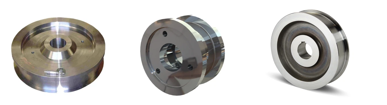
The wheels provide support for the crane structure and are essential for allowing the gantry crane to travel along its track.They also absorb the forces generated by the crane's weight and operational movements, distributing these forces to prevent damage to the track and other crane components.
Depending on the crane's purpose and the loads it handles, the wheels are engineered to handle different weight capacities. Larger cranes or those used for heavier lifting will have larger, more robust wheels.
2) Design requirements
Crane wheels are typically made of high-strength steel or alloy materials to withstand the weight of the crane and its load while enduring constant motion and heavy loads.The wheels are often designed with a flange to ensure smooth and stable movement along the rails and to prevent them from derailing.
7.Crane Hook
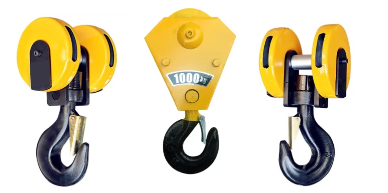
The crane hook of a cantilever gantry crane is an essential component in the lifting and handling process. This hook is used to attach and support loads during hoisting operations.
The hook is typically made of high-strength steel to handle heavy loads. It has a curved shape, with a deep throat for secure attachment to slings, chains, or other lifting devices.The hook usually has a safety latch to prevent the load from accidentally coming loose during operation.
The primary function of the crane hook is to connect the crane's lifting mechanism (such as the hoist) with the load. It moves along the gantry crane's beam (which is supported by the legs of the gantry structure) and can be raised or lowered depending on the lifting requirements.
Motor
The motor of a cantilever gantry crane is a crucial component responsible for driving the various movements of the crane, such as the hoisting, trolley travel, and gantry movement. Depending on the design and size of the crane, the motor can vary in type and specifications. The motors are typically controlled by a PLC (Programmable Logic Controller) or VFDs (Variable Frequency Drives) to adjust speeds and torque for efficient operation.
Hoisting Motor:Purpose: Drives the hoist to lift and lower the load.Motor Type: Typically an electric motor, often an AC induction motor.Power: Varies depending on the load capacity, ranging from a few kW to several hundred kW.
Travelling Motor (Trolley Movement):Purpose: Moves the trolley along the gantry rail.Motor Type: Usually a three-phase AC motor.Power: Selected based on the required speed and capacity of the trolley.
Gantry Traveling Motor (Bridge Movement):Purpose: Moves the entire gantry structure along the ground rail, allowing it to span over the load area.Motor Type: A heavy-duty electric motor, often with a variable speed drive (VSD) for fine control.Power: Similar to the trolley motor but typically higher, as it needs to move the entire crane structure.

.
Sound and light alarm system & limit switch
1) Sound and light alarm system
The sound and light alarm system for a Cantilever Gantry Crane is designed to enhance safety by providing visual and audible signals in case of abnormal conditions or hazards. These alarms help warn operators, workers, and personnel in the vicinity of potential risks.
Sound Alarm (Horn or Siren):Purpose: Alerts personnel to an emergency or abnormal situation.Sound: Typically loud and attention-grabbing, such as a siren or a horn with varying patterns (continuous, intermittent, or pulsed) to signal different types of alerts.Placement: Usually installed at the crane's control cabin, near the gantry, or at strategic locations where workers are most likely to be present.
Light Alarm (Strobe Light or Flashing Beacon):Purpose: Provides a visual alert that can be seen in areas where sound alone might not be effective (e.g., in noisy environments or at a distance).Light Type: Flashing or rotating strobe lights or beacons are commonly used, often with different colors to indicate different warning levels.
Red: Critical alarm (dangerous situation).
Yellow/Amber: Caution (warning or a non-urgent issue).
Blue: May indicate operational status or a different specific condition.
2) Limit switch
A limit switch on a cantilever gantry crane is a safety device used to prevent the crane from over-traveling or moving beyond its predefined limits. It is an essential component for ensuring the proper and safe operation of the crane. The cantilever gantry crane typically consists of a large structure with a bridge and hoisting mechanism, which is often used in industrial environments like ports or warehouses for lifting and moving heavy loads.
Function of the Limit Switch:
Position Detection: The limit switch detects when the crane's hoist or trolley has reached its designated end position (either fully raised, lowered, or moved along the track). This helps prevent mechanical damage caused by over-travel.
Safety: It acts as a fail-safe to stop the crane from moving if it reaches its boundary. This reduces the risk of accidents and protects both the crane and surrounding equipment.
Automation: Limit switches can be connected to the crane's control system. When the limit switch is triggered, it sends a signal to the control system to stop the crane or reverse its direction.
Types of Limit Switches for Gantry Cranes:
Mechanical Limit Switch: This type uses a physical actuator to open or close contacts when the crane reaches a limit. It is a commonly used, simple, and cost-effective solution.
Magnetic Limit Switch: These use magnetic fields to detect the position of a target without direct contact, providing a more durable and longer-lasting solution.
Proximity Limit Switch: It detects the presence of a target without contact, using a sensor, and is often used in more advanced or higher-speed applications.

10.Safety Devices
1) 1. Overload Protection Device
Prevents the crane from lifting loads exceeding its rated capacity.
Activates an alarm or cuts off power to the lifting mechanism when the load exceeds safe limits.
2. Limit Switches
Hoisting Limit Switch: Stops the lifting mechanism when the hook reaches its upper or lower limit to prevent over-hoisting or over-lowering.
Travel Limit Switch: Restricts the horizontal movement of the crane or trolley to avoid collisions or derailments.
Boom Angle Limit Switch (if applicable): Ensures the boom does not exceed safe angular limits.
3. Emergency Stop Button
Allows operators to instantly halt crane operations in case of an emergency.
Usually installed in multiple accessible locations on the crane and remote controls.
4. Anti-Collision Devices
Uses sensors (proximity sensors or lasers) to detect obstacles or other equipment in the crane's path, preventing collisions.
May include audible alarms or automatic braking systems.
5. Wind Speed Monitoring System
Monitors wind speed and issues alerts when it exceeds safe levels for operation.
Some systems automatically lock the crane or anchor it during high winds.
6. Braking System
Mechanical Brakes: Ensures the load remains stationary when not in motion.
Emergency Braking System: Activates during power failure or system malfunction.
7. Rail Clamp or Storm Lock
Locks the crane in position during storms or high winds to prevent movement.
8. Buffer System
Installed at the end of the crane's travel path to absorb impact and reduce damage during accidental over-travel.
9. Load Moment Indicator (LMI)
Monitors the load moment and alerts the operator if the crane approaches its tipping point.
10. Safety Interlocks
Ensures specific operations, such as lifting, trolley movement, or boom adjustment, cannot be performed simultaneously in an unsafe manner.
11. Audible and Visual Warning Systems
Alarms: Alert nearby personnel during crane operation or in the event of a fault.
Signal Lights: Indicate the crane's operational status.
12. Wire Rope Inspection and Safety Features
Rope Overwind Protection: Prevents the wire rope from being wound improperly, which could lead to accidents.
Rope Break Detection: Detects breakage or slack in the wire rope and halts the operation.
13. Operator Cabin Safety Features
Ergonomically designed controls to minimize operator fatigue.
Fire extinguishers and other emergency equipment are typically available in the cabin.
14. Automatic Crane Monitoring System (Optional)
Monitors critical parameters such as load, speed, and temperature.
Records operational data and faults for maintenance and troubleshooting.
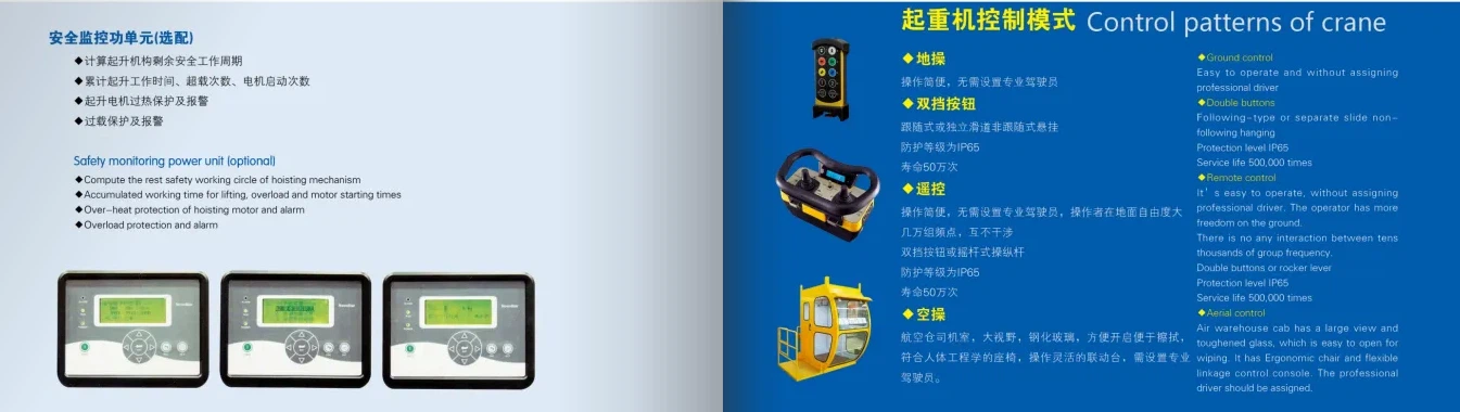
11.Control Mode
1)1. Manual Control
Description: Operators manually control the crane using push-button pendants, levers, or control panels directly on-site.
Features:
Simple to use and maintain.
Suitable for less complex lifting tasks.
Applications: Used in smaller-scale operations or locations with low automation requirements.
2. Remote Control
Description: Operators use a wireless remote control device to operate the crane from a safe distance.
Features:
Improved safety by allowing the operator to stay clear of the load.
Greater operational flexibility.
Can handle more complex movements.
Applications: Warehousing, logistics yards, and other environments requiring higher precision.
3. Cabin Control
Description: The operator sits in a cabin attached to the crane and controls operations using joysticks or control panels.
Features:
Provides the operator with a clear view of the load and working area.
Suitable for heavy-duty and long-duration operations.
Applications: Large-scale industrial sites, such as shipyards, steel mills, or construction sites.
4. Semi-Automatic Control
Description: Some operations (like repetitive movements) are automated, while others require manual input.
Features:
Reduces operator workload.
Increases efficiency for repetitive tasks.
Applications: Assembly lines, logistics hubs, and tasks involving repeated lifting and positioning.
5. Fully Automatic Control
Description: The crane operates autonomously based on pre-programmed instructions or sensor inputs.
Features:
High precision and efficiency.
Eliminates human error and reduces labor costs.
Often integrated with smart systems or IoT for monitoring and data analysis.
Applications: Ports, automated warehouses, and environments requiring high-speed, precise operations.
6. Hybrid Control (Manual + Automatic)
Description: Combines manual and automatic control options, allowing flexibility based on task requirements.
Features:
Adaptable to varying operational needs.
Enhances efficiency without sacrificing control.
Applications: Sites that require both human supervision and automation.
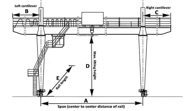
12.Sketch
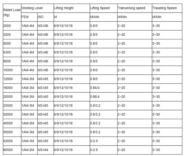
Main technical
Advantages
1. High Load Capacity and Structural Strength
Designed to handle up to 80 tons of material with stability and safety.
The double girder design provides superior load distribution and rigidity compared to single girder types.
2. Wide Span and Coverage
Supports large spans (typically 18–35 meters or more), allowing it to service wide working areas.
Ideal for large-scale operations such as steel yards, shipyards, and construction sites.
3. Enhanced Lifting Height
The hoist travels on top or between the girders, enabling greater lifting height than single girder cranes, especially useful for tall loads or structures.
4. Flexible Application
Suitable for indoor and outdoor use.
Can be customized with cantilevers, rail systems, lifting attachments, or multiple hoists for specific tasks.
5. Durable and Weather-Resistant Design
Built with high-strength steel, anti-corrosion coatings, and wind-resistant mechanisms such as rail clamps and storm locks for outdoor environments.
6. Smooth Operation and Accurate Control
Equipped with variable frequency drives (VFDs) for precise movement and reduced mechanical stress.
Offers soft start/stop features and accurate load positioning.
7. Multiple Control Options
Operated via cabin, remote control, or pendant, depending on site needs and operator preference.
Improves safety and operational efficiency.
8. Advanced Safety Systems
Includes overload protection, limit switches, emergency stops, and anti-collision systems.
Reduces the risk of accidents and equipment damage.
9. Long Service Life
Engineered for medium to heavy-duty work cycles (A5–A7 classification), providing years of reliable service with proper maintenance.
Application
1. Construction Industry
Lifting heavy construction materials like steel beams, concrete blocks, and other construction components.
Transporting and positioning materials at construction sites.
2. Manufacturing Facilities
Handling large components or machinery in production lines.
Moving raw materials or finished goods within the plant.
3. Shipyards and Ports
Loading and unloading containers or cargo from ships.
Transporting heavy ship components or maintenance equipment.
4. Warehousing and Logistics
Stacking and organizing goods in outdoor or indoor storage areas.
Loading and unloading trucks or railcars.
5. Aerospace and Aviation
Handling large aircraft components, such as fuselages, wings, or engines.
Supporting maintenance and assembly operations.
6. Railway Yards
Lifting and positioning railway components like tracks or bogies.
Loading and unloading railway cargo.
7. Steel Mills and Foundries
Moving heavy steel plates, coils, or castings.
Handling molten metal containers.
8. Mining and Heavy Industries
Transporting heavy equipment and materials in mining operations.
Handling large machinery for assembly or repair.
9. Power Plants
Installing or maintaining turbines, generators, and other heavy power equipment.
Transporting fuel or waste containers in nuclear or thermal plants.
Crane production procedure
1. Design and Engineering
Requirement Analysis
Understand the client's specifications (load capacity, span, height, working environment, etc.).
Determine operational parameters: lifting height, travel speed, working frequency, etc.
Preliminary Design
Create conceptual designs and 3D models.
Choose materials based on strength and environmental conditions.
Detailed Engineering
Develop detailed engineering drawings (structural components, mechanisms, electrical systems).
Perform stress and fatigue analysis to ensure safety.
2. Material Procurement
Source high-quality materials, including:
Steel plates and profiles for structural components.
Motors, gearboxes, and other mechanical parts.
Electrical systems and control components.
Inspect materials to ensure compliance with quality standards.
3. Fabrication
Structural Component Fabrication
Cut, weld, and assemble the steel structures (main girder, cantilever arms, legs, etc.).
Ensure precise alignment and dimensions.
Perform surface treatment (e.g., shot blasting, painting) for corrosion protection.
Mechanical Assembly
Assemble mechanical parts (trolley, hoist, wheels, etc.).
Install motors, gearboxes, and drive systems.
Electrical Assembly
Install electrical components (control panels, cables, sensors).
Wire and connect the system to ensure functionality.
4. Quality Inspection
Material Inspection
Verify material certification and conduct tests (e.g., tensile tests).
Structural Inspection
Inspect weld quality (e.g., ultrasonic testing).
Ensure dimensional accuracy and surface finishing.
Assembly Inspection
Check alignment and functionality of all parts (mechanical and electrical).
Load Testing
Conduct static and dynamic load tests to ensure safe operation.
5. Factory Acceptance Testing (FAT)
Conduct a comprehensive trial run, including:
Full load and overload tests.
Functionality of all safety devices (e.g., limit switches, emergency brakes).
Smooth operation of trolley, hoist, and crane travel.
Document results and obtain client approval.
6. Disassembly and Packing
Disassemble the crane into transportable sections.
Pack components securely to prevent damage during transportation.
Label and prepare a packing list for efficient reassembly.
7. Transportation
Deliver the crane components to the installation site using appropriate transportation methods.
8. Installation and Commissioning
On-Site Assembly
Assemble structural components and mechanical systems.
Install electrical systems and control panels.
Calibration and Testing
Recalibrate the crane system for site-specific conditions.
Perform on-site load testing to verify performance.
9. Handover
Provide training to the client's personnel on safe operation and maintenance.
Deliver technical documentation (user manual, maintenance guide, certificates).
Obtain final approval and acceptance from the client.
10. After-Sales Support
Offer warranty services and maintenance support.
Provide spare parts and technical assistance as needed.

Workshop view:
The company has installed an intelligent equipment management platform, and has installed 310 sets (sets) of handling and welding robots. After the completion of the plan, there will be more than 500 sets (sets), and the equipment networking rate will reach 95%. 32 welding lines have been put into use, 50 are planned to be installed, and the automation rate of the entire product line has reached 85%.




Hot Tags: 80 ton double girder gantry crane, China 80 ton double girder gantry crane manufacturers, suppliers, factory
You Might Also Like


Send Inquiry