


100 Ton Rail Mounted Gantry Crane
Products Description
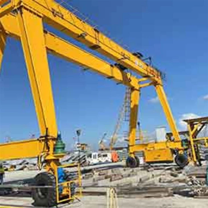
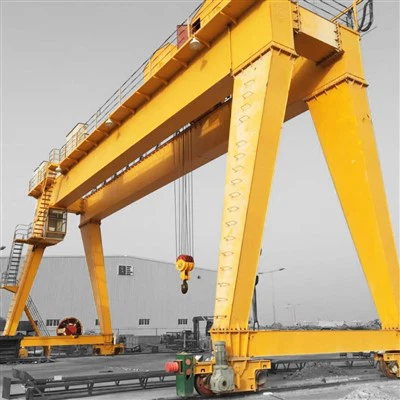
A 100-ton rail mounted gantry crane (RMG crane) is a heavy-duty lifting solution engineered for high-capacity material handling in industrial environments such as ports, shipyards, container yards, and large manufacturing plants. Designed to run on fixed rails, this crane offers precision movement, high load capacity, and robust structural integrity to handle the most demanding lifting operations.
Typically powered by electricity, the 100-ton RMG crane consists of a bridge supported by legs that run on rails, with a trolley and hoist system that travels along the bridge for horizontal and vertical movement. Its advanced control systems allow for smooth, efficient, and safe handling of oversized or heavy cargo, including containers, steel structures, machinery, and large prefabricated components.
Key advantages include:
High lifting capacity (up to 100 tons)
Excellent stability and precision
Automation capabilities for improved efficiency
Customizable span and height to fit project needs
Reduced operational costs compared to mobile cranes
Due to their fixed-track design, RMG cranes are ideal for repetitive, high-volume operations where space and path are well-defined.
Core Components:Engine, Bearing, Gearbox, Motor, Gear
Place of Origin:Henan, China
Warranty:2 years
Weight (KG):50000 kg
Video outgoing-inspection:Provided
Machinery Test Report:Provided
Application:Outdoor
Keywords:Gantry Crane
Rated Loading Capacity:50Ton
Cross travelling speed:44.6m/min
Long travelling speed:47.1m/min
Control way:cabin
Power supply:Cable reel
Steel track:QU80
Power:3-phase AC 50HZ 380V

Pictures & Components
1.Bridge/Girder
The main horizontal beam structure spanning the width of the crane.
Supports the trolley and hoist mechanism.
Can be a single or double girder depending on design and load requirements.
Legs
Vertical supports that connect the bridge to the rail system.
Typically two or four legs, depending on the span and load.
Some legs may be rigid while others allow slight flexibility for alignment.
Functions
Support for Lifting Mechanism: It houses the trolley and hoist that carry out lifting tasks.
Stability: Ensures the stability of the crane by evenly distributing loads.
Efficiency: Designed to optimize load movement across the working area.
Design Considerations
Load Requirements: Calculated based on the maximum load and dynamic forces the crane will encounter.
Span and Height: Dictated by the size of the workspace and the required lifting height.
Safety Factors: Includes features like deflection limits, fatigue resistance, and compliance with industry standards (e.g., FEM, CMAA).
Trolley
Moves horizontally along the bridge/girder.
Houses the hoisting mechanism (winch, wire rope, motor).
Responsible for lateral movement of the load.
Hoisting Mechanism
Includes the hoist, motor, drum, gearbox, and wire rope or chain.
Performs the vertical lifting and lowering of loads.
Designed to handle 100-ton capacity with appropriate safety factors.
 |
 |
3.End carriage
1) The end carriage of a Double Main Girder Gantry Crane is a critical component of its structural and operational system. It connects the main girders to the wheels or tracks, providing stability and ensuring the crane's structural integrity.Equipped with wheels or bogies, the end carriage enables the crane to move along the tracks laid on the ground or across gantry beams.Distributes the weight of the crane and the load evenly across the wheels and tracks.
2) The end beam is typically made of high-strength steel to withstand heavy loads and environmental conditions.
3) The end beam is designed to support the specific load-bearing requirements of the crane.
 |
 |
4.Crane travelling mechanism
1) Working principle
The wheels are attached to axles or wheel blocks that help in distributing the load evenly across the crane.The drive motor activates the wheels through a system of gears and reducers, converting the motor's rotational force into torque.The wheels, mounted on the frame of the crane, roll along the rails on which the gantry structure is placed.The power to the wheels is transmitted via a combination of chains, belts, or direct coupling depending on the design of the crane.The crane traveling mechanism of a Double Main Girder Gantry Crane involves synchronized wheel and motor systems that enable the crane to move along its designated rails, with additional features ensuring safe, balanced, and efficient operation.
2) Functions of the crane operating mechanism
Horizontal movement: The primary function of the crane travelling mechanism is to move the entire crane structure along the rails or tracks that are placed on the ground or the sides of the installation area.
Support and Stability:The travelling mechanism ensures the crane is securely supported on the rails or tracks. It helps distribute the weight of the crane evenly and provides stability during movement.
Power Transmission:The crane travelling mechanism is powered by electric motors that drive wheels or gear systems. These motors convert electrical energy into mechanical energy, propelling the crane forward or backward.
Load Distribution:The travelling mechanism helps distribute the load evenly across the crane's wheels and tracks, preventing damage and ensuring the durability of the crane and its components.
5.Trolley travelling mechanism
1) Structural composition
Trolley frame: The frame is typically made of high-strength steel to support the load and withstand the stresses during operation.
Wheel set: The trolley is equipped with wheels that run on the rails of the main girder. These wheels are often made of hardened steel or cast steel to ensure durability and wear resistance.
Drive device: Electric motors are commonly used to provide the necessary power for the trolley's movement A gearbox is used to control the speed and torque of the trolley's movement.Couplings connect the motor to the gearbox and ensure smooth transmission of power to the wheels.
.
2) Function of the trolley operating mechanism
Horizontal Movement: The primary function of the trolley traveling mechanism is to move the trolley horizontally across the length of the main girders. This movement allows the crane to position the hoist over a desired load location.
Load Handling: By moving along the main girders, the trolley helps in positioning the hoist system accurately above the load, which is necessary for lifting and transferring goods efficiently.
Power Transmission: The traveling mechanism typically uses electric motors and gear systems to provide the necessary torque and speed for the trolley's movement. The motors can be either AC or DC, depending on the design and requirements of the crane.
Rails and Wheels: The trolley runs on rails that are mounted on the main girders. The wheels on the trolley are designed to travel along these rails, ensuring smooth and stable movement. The wheels may be fitted with flanges to prevent lateral movement and maintain alignment.
Safety Mechanisms: The traveling mechanism is equipped with safety features such as limit switches, braking systems, and overload sensors to prevent accidents and ensure the safe operation of the crane.
6.Crane wheel
1) Function of wheels
Load Bearing: In a double main girder gantry crane, each wheel supports a significant portion of the crane's load. The wheels must be engineered to handle both the static and dynamic loads imposed during lifting operations.
Material Handling and Safety: The design of crane wheels must ensure safe operation, especially when handling heavy or oversized loads. The wheels should be engineered to minimize noise and vibrations during operation.
Rail Compatibility: Crane wheels are designed to run on specific rail types (e.g., flat or curved tracks). The size and shape of the wheel flange must match the rail profile to ensure proper fit and smooth operation.
2) Design requirements
Material and Design: Crane wheels are typically made of high-strength steel or cast iron to withstand the heavy loads and stresses associated with lifting and transporting materials. The design often includes a flange to ensure proper alignment and prevent the wheels from derailing off the tracks.

7.Crane Hook
The crane hook of a double main girder gantry crane is an essential component used for lifting and transporting heavy loads.
Design and Structure
Material: Typically made of high-strength steel to withstand heavy loads and provide durability.
Shape: The hook often has a C-shape or a pointed end for securely holding lifting slings or chains.
Size and Capacity: It is designed to match the lifting capacity of the crane, which can range from a few tons to several hundred tons for large industrial cranes.
Types of Hooks
Single Hook: Common in standard applications, used for lifting a load from a single point.
Double Hook: Utilized when a more balanced load is needed, often in double main girder designs for higher lifting capacities.
Crab Hook: In gantry cranes, the hook may be mounted on a trolley or crab that runs along the girders.

Power Supply System
Typically through cable reels, festoon systems, or conductor bars.
Supplies electric power to the motors and control systems.

.
Sound and light alarm system & limit switch
1) Sound and light alarm system
A double main girder gantry crane, commonly used in heavy-duty operations, often incorporates safety mechanisms like sound and light alarm systems to ensure safe operations.
Sound Alarm (Horns/Buzzers): These are typically loud, audible devices that emit a distinctive sound to alert people in and around the working area. The sound level is designed to be high enough to be heard over operational noise.
Light Alarm (Flashing Lights/Beacons): Visual signals, such as flashing lights or rotating beacons, help alert personnel visually, especially in noisy environments where sound alarms may be insufficient.
2) Limit switch
A limit switch on a Double Main Girder Gantry Crane is a safety device used to prevent the crane from moving beyond a designated range. This ensures the protection of both the crane and its surroundings, as well as any loads being lifted.
Key Functions of Limit Switches:
Position Control: The limit switch helps monitor and control the position of the crane's trolley, hoist, and gantry to prevent over-travel and collisions.
Safety Shutdown: If the crane moves past its allowed limits, the limit switch signals the control system to stop the motor and prevent damage or hazardous situations.
Emergency Stop: It can act as an emergency cutoff to shut down the crane when it approaches the limits of its track or rail, preventing it from derailing or causing accidents.
Types of Limit Switches Used:
Mechanical Limit Switches: Activated by physical contact, often using a lever or cam that triggers the switch when moved by the crane's motion.
Electronic Limit Switches: Use sensors (e.g., inductive, capacitive, or optical sensors) for non-contact detection, providing higher durability and reducing wear and tear.
Rotary Limit Switches: Typically used in applications where rotational motion needs to be monitored, such as in hoists.
Linear Limit Switches: Used for applications where linear travel is monitored, commonly found in the movement of the trolley.

10.Safety Devices
1) 1. Overload Protection Device
Function: Prevents the crane from lifting loads that exceed its rated capacity.
2. Limit Switches
Function: Prevents the crane from moving beyond a set range during operations.
3. Emergency Stop Button
Function: Allows operators to quickly shut down the crane in case of an emergency.
4. Anti-Collision Device
Function: Prevents collisions between the crane and other structures or equipment.
5. Load Sway Control
Function: Reduces load sway during operations, which can be dangerous if uncontrolled.
6. Brake Systems
Function: Ensures that the crane remains in a stationary position when not in motion.
7. Safety Interlocks
Function: Prevents the operation of the crane if certain safety conditions are not met.
8. Warning Alarms and Signal Lights
Function: Alerts personnel in the vicinity of the crane's movement.
9. Anti-Tipping Device
Function: Protects against crane tipping due to uneven load distribution or excessive loading.
10. Cooling System for Motors
Function: Prevents motors from overheating during extended use.
11. Remote Control Systems
Function: Allows operators to control the crane from a safe distance.
12. Crane Monitoring Systems
Function: Provides real-time monitoring of operational parameters such as load weight, speed, and position.
13. Lighting and Visibility Aids
Function: Ensures that the operator has clear visibility, especially in low-light conditions.
11.Control Mode
1)1. Pendant Control
Description: The crane operator uses a wired control pendant to manage the movement of the crane and hoist.
Advantages: Simple to use, cost-effective, and provides direct control from a safe distance.
Usage: Commonly used in stationary or semi-stationary operations where the operator can be close to the crane.
2. Radio Remote Control
Description: Operators use a wireless control unit, which communicates with the crane via radio signals.
Advantages: Offers more flexibility as the operator can control the crane from a greater distance and access hard-to-reach areas.
Usage: Ideal for more complex operations and environments where operator mobility is essential.
3. Cabin Control
Description: The operator sits in a cabin on the crane itself and controls it using a combination of joysticks, buttons, or other controls.
Advantages: Provides a better view of the working area and greater precision in controlling the crane.
Usage: Suitable for heavy-duty operations or when a higher level of control is needed for positioning and maneuvering.
4. Automated Control (Semi-Automatic and Fully Automated)
Description: The crane can be controlled by programmed commands or integrated with automated systems for autonomous operation.
Advantages: Reduces human intervention, improves precision, and enhances safety for repetitive tasks.
Usage: Often used in large-scale operations where high efficiency and continuous operation are necessary.
5. Hybrid Control
Description: Combines manual operation (using pendant, remote, or cabin control) with automated features that can be engaged as needed.
Advantages: Offers versatility for operators who need to switch between manual and automated modes for specific tasks.
Usage: Common in systems designed to be adaptable to various operational requirements.

12.Sketch

Main technical

Advantages
1. High Lifting Capacity
Designed to handle extremely heavy loads (up to 100 tons), making it ideal for large containers, steel structures, machinery, and prefabricated components.
2. Stable and Precise Operation
Rail-mounted design ensures consistent movement along a fixed path, providing excellent stability and precise load positioning-especially critical for repetitive lifting tasks.
3. Efficient Material Handling
Ideal for high-throughput environments such as container terminals, shipyards, and large industrial facilities.
Increases productivity by reducing loading/unloading times.
4. Customizable Span and Height
Can be engineered to match specific site layouts, including wide spans, high lifting heights, or narrow working aisles.
5. Reduced Operational Costs
Electric drive systems are more cost-efficient and environmentally friendly than diesel-powered alternatives.
Lower maintenance compared to mobile cranes due to fewer moving parts and a fixed-track system.
6. Automation and Remote Operation Capabilities
Can be equipped with remote controls, semi-automated or fully automated systems for enhanced safety and efficiency.
Smart features such as anti-sway, positioning systems, and load monitoring improve operation.
7. Durability and Long Lifespan
Engineered for rugged, continuous-duty applications.
Constructed with heavy-duty steel and corrosion-resistant components, especially important for outdoor or coastal environments.
8. Safe Working Environment
Equipped with advanced safety systems: overload protection, emergency brakes, limit switches, wind locks, and anti-collision devices.
Application
1. Port and Container Terminals
Primary use: Lifting and stacking standard shipping containers.
Ideal for container yards that require high-capacity, rail-mounted systems for efficient cargo handling.
Ensures fast turnaround times in loading/unloading vessels and rail cars.
2. Shipyards and Marine Engineering
Used for moving large ship components, engines, or prefabricated sections during vessel construction or repair.
The 100-ton capacity allows safe handling of oversized, heavy modules.
3. Steel and Metal Fabrication Yards
Handles heavy steel beams, coils, plates, and structural components.
Essential for environments where precision and strength are critical for large-scale assemblies.
4. Precast Concrete Plants
Lifts large precast elements such as bridge girders, wall panels, or concrete slabs.
Helps transport components from casting areas to curing zones or storage.
5. Power Plants and Energy Facilities
Used in the construction and maintenance of hydroelectric, nuclear, and thermal power plants.
Moves massive components like turbines, generators, or structural assemblies.
6. Heavy Equipment Manufacturing
Supports production lines where large machinery or equipment frames are assembled or transported.
Offers precise handling during welding, assembly, or installation processes.
7. Railway and Locomotive Yards
Moves railcars, bogies, or heavy mechanical parts during repair, maintenance, or assembly.
Often integrated into railcar manufacturing facilities.
Crane production procedure
1. Design and Engineering
Blueprint and Structural Design: Engineering teams design the crane based on specifications, considering the weight, span, lifting capacity, and working environment.
Component Specifications: Detailed specifications for components such as the main girders, end beams, hoist system, trolley, and electrical components are prepared.
2. Material Selection and Procurement
Steel Material Selection: High-strength steel materials are chosen for the main girders, columns, and other critical parts.
Procurement: Materials, such as steel plates, sections, bolts, and electrical components, are sourced and inspected for quality.
3. Cutting and Pre-Fabrication
Cutting and Shaping: Steel components are cut, shaped, and welded into preliminary forms according to the design specifications.
Pre-Fabrication Assembly: Components such as beams and girders are pre-assembled to verify that they fit together properly.
4. Welding and Structural Assembly
Welding: Main girders, columns, and other structural components are welded to create a sturdy framework. Specialized welding techniques are used to ensure strength and durability.
Structural Assembly: The main girders and end beams are assembled, ensuring precise alignment for balanced load distribution.
Quality Control: Welding seams and joints are inspected using non-destructive testing (e.g., ultrasonic or X-ray testing) for any structural defects.
5. Machining and Finishing
Machining of Parts: Critical parts such as the wheels, trolley components, and hoists undergo machining for proper fitting and smooth operation.
Surface Treatment: Steel parts are cleaned and subjected to surface treatments like sandblasting and coating to prevent rust and enhance durability.
Painting and Coating: Protective coatings are applied for weather resistance, with a primer followed by top coats.
6. Assembly of Crane Components
Main Girder Assembly: The two main girders are mounted and aligned.
End Beam Installation: End beams are fixed to the main girders, forming the frame of the crane.
Hoist and Trolley Installation: The hoist mechanism and trolley are mounted on the main girder rails and tested for alignment and operational smoothness.
7. Electrical and Control Systems Installation
Wiring and Cabling: Electrical wiring is installed for power supply, control circuits, and safety systems.
Control Panel and Safety Features: The control panel is mounted, with safety features such as limit switches, emergency stops, and overload protection integrated and tested.
Control System Programming: The crane's control system is programmed and tested for correct operation.
8. Testing and Quality Assurance
Load Testing: The crane is subjected to load tests to ensure it can handle its rated capacity without issues.
Operational Testing: Functional tests are performed to check movements, responsiveness, braking systems, and electrical operations.
Inspection and Certification: The crane undergoes final inspections to verify compliance with safety regulations and standards. Certification may be issued by relevant authorities.
9. Final Adjustments and Delivery Preparation
Final Adjustments: Any minor adjustments are made to ensure smooth operation.
Documentation: Operation manuals, maintenance guidelines, and certification documents are prepared for delivery.
Packaging and Shipping: The crane is packaged securely for shipment, ensuring all parts are protected during transit.
10. Installation and Commissioning (at Site)
On-site Assembly: The crane is assembled at the customer's location if required.

Workshop view:
The company has installed an intelligent equipment management platform, and has installed 310 sets (sets) of handling and welding robots. After the completion of the plan, there will be more than 500 sets (sets), and the equipment networking rate will reach 95%. 32 welding lines have been put into use, 50 are planned to be installed, and the automation rate of the entire product line has reached 85%.


Hot Tags: 100 ton rail mounted gantry crane, China 100 ton rail mounted gantry crane manufacturers, suppliers, factory, Upper Rotary Electromagnetic Bridge Crane, Ladle Foundry and Casting Steel Mill Overhead Crane, Magnetic Overhead Crane, Metallurgical Crane, Single Beam Explosion Proof Overhead Crane, Forged Wheel
You Might Also Like


Send Inquiry