










Heavy Load Capacity Bridge Concrete Beam Erection Machine manufacturers

Heavy Load Capacity Bridge Concrete Beam Erection Machine suppliers
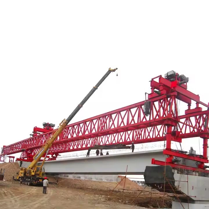
Heavy Load Capacity Bridge Concrete Beam Erection Machine factory

Heavy Load Capacity Bridge Concrete Beam Erection Machine best

Heavy Load Capacity Bridge Concrete Beam Erection Machine high quality
Heavy Load Capacity Bridge Concrete Beam Erection Machine
A Heavy Load Capacity Bridge Concrete Beam Erection Machine is also called a Bridge Girder Launcher, Beam Launcher, or Bridge Erection Gantry. It is specialized heavy construction equipment used to lift, transport, and place massive precast concrete bridge beams during highway, railway, metro, and viaduct construction projects.

Main Functions
The machine performs:
Lifting precast concrete girders
Transporting beams along the bridge alignment
Positioning beams precisely on bridge piers
Launching forward to the next span automatically
Key Design Parameters & Performance Specifications
| Parameter | Specification |
|---|---|
| Lifting Capacity (per girder) | 150-180ton Metric Tons |
| Maximum Span (Pier to Pier) | 50 meters (Typical), customizable up to 60m |
| Minimum Curve Radius | 2,000 meters (can be designed for tighter radii) |
| Maximum Supported Grade | ±4% |
| Lifting Hoists | 2 x Main Hoists (typically 120-ton capacity each) |
| Hoist Lifting Speed | 0-5 m/min (variable speed control) |
| Trolley Traversing Speed | 0-10 m/min (variable speed control) |
| Main Beam Launching Speed | 0-5 m/min (variable speed control) |
| Machine Self-Propelling Speed | 0-5 m/min (variable speed control) |
| Control System | Centralized PLC with frequency control for all motions. Remote control operation. |
| Power Supply | 380V / 50Hz / 3 Phase (or as per project requirement) |

Pictures & Components
A Heavy Load Capacity Bridge Concrete Beam Erection Machine consists of several major structural, mechanical, hydraulic, and electrical components that work together to lift and place precast bridge girders safely and accurately.
Main Components
1. Main Girder (Launcher Girder)
The primary steel truss or box structure of the machine.
Functions:
Carries the lifting load
Supports hoists and trolleys
Transfers beam weight to support legs
2. Front Support Leg
Located near the front end of the launcher.
Functions:
Supports machine during launching
Transfers load to bridge pier
Stabilizes front section
Features:
Adjustable height
Hydraulic support cylinders
Roller assemblies
3. Rear Support Leg
Located at the rear side of the machine.
Functions:
Balances rear load
Supports launcher during beam movement
Assists forward launching
4. Lifting Trolley / Winch Trolley
Travels along the main girder.
Functions:
Lifts concrete beam
Moves beam longitudinally
Positions beam accurately
Components:
Electric hoist
Winch drums
Wire ropes
Pulley blocks
Motors and brakes
Capacity:
Often 100–500+ tons
5. Hoisting System
The actual lifting mechanism.
Includes:
Wire rope drums
Hydraulic winches
Hook blocks
Sheaves/pulleys
Lifting spreader beams
Purpose:
Raises and lowers girders safely
6. Traveling Mechanism
Allows machine movement.
Types:
Rail-mounted wheels
Bogie assemblies
Self-propelled hydraulic drive
Movement:
Longitudinal travel
Transverse travel
Launching movement
7. Hydraulic System
Provides controlled power for lifting and launching.
Components:
Hydraulic cylinders
Pumps
Valves
Hydraulic hoses
Oil reservoir
Functions:
Jacking
Leg adjustment
Steering
Synchronization
8. Electrical Control System
Controls machine operation and automation.
Includes:
PLC controller
VFD drives
Sensors
Remote control
Operator cabin
Limit switches
Functions:
Synchronized lifting
Safety monitoring
Motion control
9. Launching Nose (Front Nose)
A lightweight front extension.
Functions:
Helps machine cross between piers
Reduces cantilever load
Improves stability during launching
Usually:
Steel truss construction
Lighter than main girder
10. Beam Carrying Device
Supports the concrete girder during movement.
Includes:
Lifting clamps
Spreader beams
Temporary supports
Suspension frames
Purpose:
Prevent beam damage
Ensure balanced lifting
11. Rail Track System
Guides movement of the machine.
Components:
Steel rails
Rail clamps
Anchors
Sleepers/supports
Used in:
Rail-mounted erection machines
12. Safety Devices
Critical for heavy-load operation.
Includes:
Overload limiter
Emergency stop
Wind alarm
Anti-collision sensor
Hydraulic lock valves
Limit switches
Tilt monitoring system

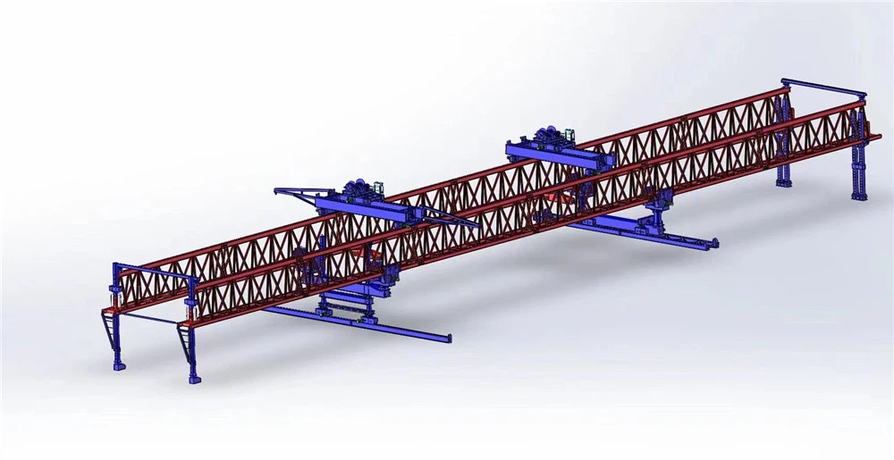
Sketch

Advantages
1. High Lifting Capacity
These machines are designed to handle extremely heavy precast concrete girders.
Advantages:
Can lift beams from 50 tons to over 1000 tons
Suitable for long-span bridges
Handles large box girders safely
2. Faster Bridge Construction
Beam erection machines significantly reduce construction time.
Benefits:
Rapid girder placement
Continuous span-by-span erection
Reduced project delays
High daily installation productivity
Typical productivity:
1–4 girders installed per day depending on span and site conditions
3. Reduced Need for Ground Support
The machine works from the completed bridge structure itself.
Advantages:
Minimal scaffolding
Less falsework
Reduced temporary supports
Ideal for rivers, valleys, highways, and deep ravines
4. Improved Safety
Modern erection machines include advanced safety systems.
Safety benefits:
Controlled synchronized lifting
Stable beam handling
Reduced manual labor at height
Lower accident risk
Automated overload protection
Common safety systems:
Wind monitoring
Emergency brakes
Hydraulic locking
Anti-collision devices
5. High Precision Beam Placement
Provides accurate girder alignment.
Advantages:
Millimeter-level positioning
Better bearing alignment
Reduced installation errors
Improved bridge quality
Especially important for:
High-speed rail bridges
Metro viaducts
Segmental bridges
6. Suitable for Difficult Terrain
Can operate where cranes are difficult or impossible to use.
Ideal locations:
Mountainous areas
Rivers and lakes
Urban expressways
Deep valleys
Existing traffic corridors
7. Reduced Traffic Disruption
Useful for bridges over active roads or railways.
Advantages:
Minimal lane closures
Faster installation windows
Reduced impact on public transportation
Commonly used in:
Metro projects
Urban flyovers
Expressway widening
8. Cost Efficiency for Large Projects
Although initial investment is high, it reduces total project cost over large-scale work.
Cost-saving areas:
Lower labor requirements
Faster completion
Reduced crane rental
Less temporary structure work
Lower traffic management costs
Best suited for:
Repetitive span construction
Long viaduct projects
9. Continuous Self-Launching Capability
The machine can move itself forward span by span.
Advantages:
No dismantling after each span
Continuous workflow
Higher efficiency
Reduced setup time
10. Adaptability
Modern systems can handle:
Straight and curved bridges
Variable spans
Different girder shapes
Sloped alignments
Compatible with:
T-beams
I-girders
Box girders
U-girders
Segmental sections
11. Better Quality Control
Precast beam construction combined with mechanized erection improves consistency.
Advantages:
Factory-produced girders
Reduced on-site concrete work
Better dimensional accuracy
Improved durability
12. Environmental Benefits
Reduced environmental impact compared to traditional methods.
Benefits:
Less ground disturbance
Reduced material waste
Lower noise in some applications
Smaller temporary footprint

Application
Applications of Heavy Load Capacity Bridge Concrete Beam Erection Machines
A Heavy Load Capacity Bridge Concrete Beam Erection Machine is widely used in modern infrastructure projects for lifting, transporting, and installing large precast concrete girders and bridge segments.
Main Applications
1. Highway Bridge Construction
Used extensively for:
Expressways
Flyovers
Interchanges
Elevated roadways
Applications:
Installing precast I-girders
Box girder erection
Multi-span highway bridges
Advantages:
Fast construction
Reduced traffic disruption
Minimal ground scaffolding
2. Railway Bridge Construction
Widely used in:
Conventional railways
Freight corridors
Heavy-haul rail systems
Functions:
Installing prestressed railway girders
Long-span rail viaduct erection
Track bridge construction
Benefits:
High alignment accuracy
Stable beam positioning
Heavy-load handling capability
3. High-Speed Rail Viaducts
One of the most important applications.
Used for:
Continuous viaduct systems
Segmental box girder erection
Long elevated rail corridors
Requirements:
Extremely high precision
Fast repetitive span erection
High safety standards
4. Metro and Urban Transit Projects
Common in cities for elevated metro systems.
Applications:
Elevated metro corridors
Urban rail transit
Monorail structures
Advantages:
Works in congested urban areas
Reduced road closure time
Faster night-time installation
Especially useful over:
Busy highways
Rail crossings
Dense urban streets
5. Segmental Bridge Construction
Used for precast segment assembly.
Applications:
Box segment erection
Balanced cantilever bridges
Long-span segmental viaducts
Functions:
Lifting individual segments
Accurate segment alignment
Temporary support during stressing
6. River and Sea Crossing Bridges
Ideal where ground access is difficult.
Applications:
River bridges
Coastal viaducts
Estuary crossings
Advantages:
No need for extensive falsework in water
Reduced marine traffic interruption
Safer over-water operation
7. Mountainous and Valley Bridges
Useful in inaccessible terrain.
Applications:
Deep valley bridges
Mountain highways
Gorge crossings
Benefits:
Minimal temporary access roads
Reduced crane dependency
Safer operation on steep terrain
8. Urban Flyover and Interchange Projects
Used in busy cities with limited working space.
Applications:
Flyovers
Elevated interchanges
Multi-level junctions
Advantages:
Compact working area
Faster span erection
Reduced public disruption
9. Long Viaduct Construction
Best suited for repetitive span projects.
Applications:
Long transportation corridors
Continuous elevated structures
Industrial transport bridges
Benefits:
Continuous launching operation
High efficiency
Cost-effective over long distances
10. Prestressed Concrete Beam Installation
Specifically designed for:
T-beams
U-girders
I-girders
Box girders
Functions:
Lifting heavy precast beams
Accurate bearing placement
Span-by-span installation

Production Procedure
Production Procedure of a Heavy Load Capacity Bridge Concrete Beam Erection Machine
The production of a Bridge Concrete Beam Erection Machine (Launching Gantry / Beam Launcher) involves structural fabrication, machining, welding, assembly, testing, and commissioning. Because these machines handle extremely heavy loads, manufacturing follows strict engineering and quality-control standards.
1. Design & Engineering Stage
The process begins with detailed engineering design.
Activities
Load calculation
Structural analysis
Finite Element Analysis (FEA)
Stability analysis
Fatigue analysis
Hydraulic system design
Electrical control design
Design Considerations
Beam weight capacity
Span length
Wind load
Deflection limits
Safety factors
Transportation constraints
Common software:
AutoCAD
SolidWorks
ANSYS
STAAD Pro
2. Raw Material Procurement
High-strength structural materials are selected.
Main Materials
High-tensile steel plates
Structural steel sections
Hydraulic components
Wire ropes
Electric motors
PLC systems
Common Steel Grades
Q345B
Q420
ASTM A572
EN S355
Material inspections include:
Chemical composition testing
Ultrasonic testing
Mill certification verification
3. Steel Plate Cutting
Steel components are cut to required dimensions.
Methods Used
CNC plasma cutting
Flame cutting
Laser cutting
Components Produced
Web plates
Flange plates
Stiffeners
Connection plates
4. Machining Process
Precision machining is performed on critical components.
Machined Parts
Wheel assemblies
Bearing housings
Gearboxes
Pin joints
Shaft systems
Machines Used
CNC milling
Lathe machines
Boring machines
Drilling machines
Purpose:
Achieve dimensional accuracy
Ensure smooth assembly
5. Structural Fabrication
Main structural sections are fabricated.
Fabricated Structures
Main girder
Support legs
Launching nose
Trolley frame
Brackets
Operations
Plate rolling
Fit-up alignment
Tack welding
Structural assembly
6. Welding Process
Heavy-duty welding is one of the most critical stages.
Welding Methods
Submerged Arc Welding (SAW)
MIG welding
FCAW welding
Manual arc welding
Important Areas
Main girder joints
Load-bearing connections
Support frames
Quality control:
Weld penetration inspection
Crack inspection
Distortion control
7. Non-Destructive Testing (NDT)
All major welds are inspected.
NDT Methods
Ultrasonic Testing (UT)
Magnetic Particle Testing (MT)
Radiographic Testing (RT)
Dye Penetrant Testing (PT)
Purpose:
Detect internal cracks
Verify weld integrity
Ensure structural safety
8. Surface Preparation
Steel surfaces are cleaned before painting.
Processes
Sandblasting
Shot blasting
Surface grinding
Standard:
SA 2.5 surface preparation
Purpose:
Remove rust and scale
Improve paint adhesion
9. Painting & Corrosion Protection
Protective coatings are applied.
Coating System
Primer coat
Intermediate epoxy coat
Polyurethane finish coat
Benefits:
Corrosion resistance
Weather protection
Extended service life
Common colors:
Yellow
Orange
Red
10. Mechanical Assembly
Mechanical systems are installed.
Installed Components
Trolleys
Wheels
Motors
Gearboxes
Wire ropes
Brakes
Bearings
11. Hydraulic System Installation
Hydraulic components are integrated.
Components Installed
Hydraulic cylinders
Pumps
Control valves
Hydraulic hoses
Oil tanks
Functions:
Lifting
Leg adjustment
Launching operations
12. Electrical & Control System Installation
Automation and electrical systems are connected.
Installed Systems
PLC control panels
Sensors
Limit switches
VFD drives
Remote control systems
Operator cabin controls
Purpose:
Motion synchronization
Safety monitoring
Automation control
13. Trial Assembly
The machine is partially or fully assembled in the factory.
Objectives
Verify alignment
Check dimensions
Test moving systems
Inspect assembly quality
14. Load Testing
Critical testing stage before delivery.
Tests Performed
No-load test
Static load test
Dynamic load test
Overload test
Testing usually:
110%–125% of rated capacity
Purpose:
Verify structural strength
Confirm operational safety
15. Disassembly & Transportation
Large machines are dismantled for shipping.
Transportation Methods
Flatbed trailers
Rail transport
Container shipment
Barge transport
Large sections include:
Main girders
Support legs
Trolleys
16. Site Installation & Commissioning
Final assembly occurs at the project site.
Activities
Structural erection
Rail installation
Electrical connection
Hydraulic calibration
Functional testing
Final checks:
Alignment
Safety systems
Synchronization
Operational trials


Workshop View
The company has installed an intelligent equipment management platform, and has installed 310 sets (sets) of handling and welding robots. After the completion of the plan, there will be more than 500 sets (sets), and the equipment networking rate will reach 95%. 32 welding lines have been put into use, 50 are planned to be installed, and the automation rate of the entire product line has reached 85%.


Hot Tags: heavy load capacity bridge concrete beam erection machine, China heavy load capacity bridge concrete beam erection machine manufacturers, suppliers, factory
Previous
200ton Bridge Erecting MachineYou Might Also Like


Send Inquiry