


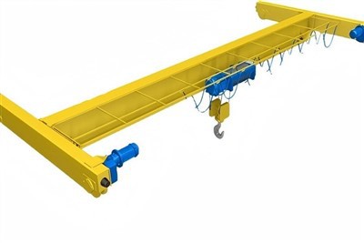
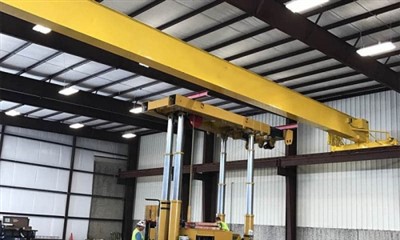
LH Model Workshop Application Overhead Crane
Products Description
What is an LH Model Overhead Crane?
The LH series typically refers to a single girder overhead crane with an electric hoist. It's characterized by its economical design, standardized components, and ease of installation. It's the workhorse crane for general material handling where extreme capacities or heavy-duty cycling are not required.
Key Characteristics:
Structure: Single girder (usually a rolled steel I-beam or a welded box girder).
Hoist: A standardized, packaged electric wire rope hoist (CD/MD type or similar) that runs along the bottom flange of the girder.
Drive: End trucks with electric motors for bridge travel; the trolley travel is integrated into the hoist unit.
Control: Most commonly pendant push-button control. Radio remote is an upgrade option.
Capacity Range: Typically from 1 ton to 20 tons.
Span: Usually up to 28-31.5 meters.
Duty Class: Generally A3 (Medium Duty) or A4 (Heavy Duty) under FEM/ISO standards, suitable for several lifts per hour.
Configuration Options for Specific Needs
While standard, the LH crane can be configured to enhance workshop utility:
Hoist Type: Choice between standard (CD) and dual-speed (MD) hoists for more precise load spotting.
Girder Type: Rolled steel girder (for shorter spans, lower cost) vs. welded box girder (for longer spans, less deflection).
Control: Pendant control (most common) or radio remote control (for better visibility and safety when the operator needs to be near the load).
Lifting Attachments: Equipped with lifting magnets for handling steel sheets, C-hooks for coils, or sheet lifters.
Special Environments: Can be built with upgraded insulation for foundry duty or explosion-proof components for hazardous areas (though this is less common for basic LH models).
Comparison with More Robust Options
| Feature | LH (Single Girder) Workshop Crane | QDY (Double Girder) Crane |
|---|---|---|
| Best For | Light/Medium duty, general workshop tasks | Heavy duty, intensive, high-precision tasks |
| Capacity | Up to 20 tons (typically 1-10t) | 5 tons to 500+ tons |
| Cost | Lowest initial and operating cost | Significantly higher |
| Headroom | Excellent (hoist under girder) | Good, but requires more built-in height |
| Duty Cycle | Intermittent to Medium (A3-A4) | Heavy to Continuous (A4-A7) |
| Precision | Good for general use | Superior (stiffer girder, top-running trolley) |
| Workshop Fit | Ideal for small to medium-sized workshops | For large industrial plants with heavy processes |
Core Components: Gearbox, Motor, Gear
Place of Origin: Henan, China
Warranty: 1 Year
Weight (KG): 10000 kg
Video outgoing-inspection: Provided
Machinery Test Report: Provided
Selling Units: Single item
Single package size: 600X300X300 cm
Single gross weight: 200.000 kg

Pictures & Components
Core Structural Components
1. Main Girder Assembly
Single Main Girder: Typically a rolled steel I-beam (for spans < 20m) or welded box girder (for spans > 20m). This is the primary horizontal load-bearing member.
End Ties/Connectors: Structural members connecting the two end trucks, providing lateral stability to the entire bridge structure.
Crane Rail: A small A45 or A55 steel rail mounted on the bottom flange of the main girder for the hoist trolley to run along.

2. End Truck Assemblies
End Truck Frame: Steel frames at each end of the crane that house the wheels and drive mechanisms.
Bridge Travel Wheels: Double-flanged steel wheels (usually 2-4 per end truck) that run on the runway rails mounted to the workshop building structure.
Bridge Drive Unit: Consists of:
Drive Motor: 0.4-1.5 kW electric motor (depending on crane weight and speed).
Reducer/Gearbox: Right-angle helical gear reducer mounted directly to the wheel shaft.
Brake: Often an electrically-released, spring-applied brake integrated into the motor.
 |
 |
Hoisting & Trolley System
3. Electric Wire Rope Hoist (Standard CD/MD Type)
This is a pre-assembled, packaged unit that serves as both the lifting mechanism and the trolley.
Hoist Frame/Shell: Enclosed steel housing containing all mechanical components.
Hoist Motor: Dual-speed (MD type) or single-speed (CD type) squirrel cage motor with thermal protection.
Reducer: Multi-stage helical gear reduction unit for torque multiplication.
Wire Rope Drum: Grooved steel drum for winding the wire rope, with precision machining for even layering.
Wire Rope: 6x19 or 6x37 class steel wire rope with independent wire rope core (IWRC).
Hook Block: Swivel hook with precision roller bearings, rated for the crane capacity with safety latch.
Upper/Lower Limit Switches: Mechanical or electronic switches to prevent over-hoisting.
4. Trolley Mechanism
Trolley Wheels: Four wheels (two driven, two idler) that run along the rail on the main girder's bottom flange.
Trolley Drive: Integrated into the hoist unit with a separate small motor and reducer for lateral movement.
Bumpers: Rubber or polyurethane buffers at trolley ends to absorb impact at travel limits.
 |
 |
Electrical & Control System
5. Power Supply System
Conductor System: One of three types:
Festoon System: Sliding trolleys on I-beam with flexible cables (most common for LH).
Conductor Bars: Enclosed insulated bars with collector shoes.
Cable Reel: For circular runways or specific applications.
Main Circuit Breaker: Located in a wall-mounted panel or on the crane bridge.
6. Control System
Pendant Control Station: Hanging push-button station with:
Up/Down buttons for hoist
Left/Right for trolley
Forward/Back for bridge travel
Emergency stop button
Control Panel: Contains:
Contactors for all three motions
Overload relays for motor protection
Control transformer (380V to lower control voltage)
Terminal blocks for wiring
Limit Switches: For bridge travel limits at both ends of the runway.

Runway System (Building Structure Interface)
7. Runway Beams & Supports
Runway Beams: Typically steel I-beams (usually larger than the crane girder) fixed to the building columns or roof structure.
Runway Rails: Standard A45, A55, or A65 crane rails mounted on top of runway beams.
Rail Clips & Bolts: Heavy-duty spring clips or bolted clamps to secure rails to beams.
Bumpers/Stops: End stops at both ends of the runway to prevent crane over-travel.
Electrical Isolation: Insulated rail joints to prevent stray currents.

Safety & Auxiliary Components
8. Essential Safety Devices
Overload Limiter: Mechanical (shear pin) or electronic device to prevent lifting beyond rated capacity (optional but recommended).
Anti-Drop Device: Secondary brake or safety gear on the hoist as backup.
Warning Devices: Buzzer or horn activated when crane moves.
Phase Failure Protection: Prevents motor operation under phase loss conditions.
Grounded Conductor: Proper grounding of all conductive parts.

.
9. Optional Workshop-Specific Attachments
Rotating Hook: For precise positioning of loads.
Magnet System: For handling steel sheets/plates (requires separate generator).
Vacuum Lifters: For non-ferrous materials or delicate surfaces.
Special Grabs: For drums, coils, or specific workshop materials.
Lighting: Crane-mounted LED work lights.

Manufacturing & Assembly Process Highlights
Girder Fabrication: Rolled I-beams are cut to span length with end connections welded. Box girders are welded from steel plate with internal stiffeners.
End Truck Assembly: Wheels, bearings, and drive units are mounted to fabricated end frames.
Painting: All components are shot-blasted and painted with industrial primer and topcoat (typically workshop grey or safety yellow).
Pre-Assembly Test: At factory, the crane is partially assembled to test functions before disassembly for shipping.
Site Installation: Components shipped separately and assembled on-site using bolted connections (no welding required).

Sketch

Main technical

Advantages
1. Exceptional Cost-Efficiency
Lower Initial Investment: Typically 30-50% less expensive than comparable double girder cranes, with simpler installation requiring less structural modification to existing buildings.
Reduced Operating Costs: Energy-efficient single motor drives (versus multiple synchronized motors) and minimal maintenance requirements translate to lower lifetime costs.
Affordable Spare Parts: Standardized, mass-produced components ensure readily available and competitively priced replacement parts.
2. Space-Optimized Design
Maximized Headroom: The underhung configuration (hoist running beneath the girder) provides optimal hook height – critical in workshops with limited ceiling clearance.
Minimal Floor Space Occupation: Unlike mobile cranes or forklifts, the LH crane operates overhead, keeping valuable floor space clear for production equipment and workflow.
Compact Profile: The single girder design creates a sleeker visual profile that feels less imposing in smaller workshop environments.
3. Installation & Operational Simplicity
Modular Assembly: Pre-engineered components allow for rapid installation (often 1-3 days) with minimal disruption to ongoing operations.
Easy Operation: Intuitive pendant controls require minimal operator training, allowing shop floor personnel to safely operate the crane with brief instruction.
Straightforward Maintenance: All critical components are easily accessible from workshop floor or portable platforms, simplifying routine inspections and repairs.
4. Reliable Performance for Standard Duties
Proven Technology: Utilizes decades-old, well-understood engineering principles with minimal failure points.
Adequate Duty Cycle: Designed for FEM/ISO A3 (Medium Duty) classification – perfect for the intermittent but regular lifting needs of most workshops (typically ≤ 150 starts/hour).
Sufficient Precision: Standard dual-speed hoists (MD type) provide both rapid movement and precise load spotting (±10mm) for most workshop tasks.
5. Safety & Compliance
Built-in Safety Features: Includes essential protections: overload limiters (optional but recommended), upper/lower limit switches, emergency stop, and phase protection.
Reduced Manual Handling Risks: Eliminates the need for dangerous manual lifting, reducing workplace injuries and associated costs.
Regulatory Compliance: When properly installed and maintained, meets or exceeds OSHA, ANSI, and other national workshop safety standards.
6. Versatility & Customization
Wide Capacity Range: Available from 1 to 20 tons, covering 95% of typical workshop lifting requirements.
Adaptable to Various Workshop Layouts: Can be configured with different span lengths, lifting heights, and power supply options (festoon, conductor bars, or cable reels).
Attachment Compatibility: Easily integrated with standard lifting attachments: hooks, magnets, vacuum lifters, and specialized grabs.
Application:
Manufacturing & Fabrication Workshops
Machine Loading/Unloading:
Feeding raw materials (steel plates, bars, billets) into CNC machines, lathes, and milling centers
Removing finished parts from work tables
Typical use: 3-5 ton capacity, 15-20m span
Workpiece Positioning:
Holding components for welding or assembly
Rotating parts for multi-side machining
Positioning heavy fixtures and jigs
Tool & Die Handling:
Installing/removing medium-weight dies in stamping presses
Moving mold assemblies in plastic injection workshops
Automotive & Transportation Workshops
Engine & Transmission Work:
Removing and installing engines in repair bays (2-3 ton capacity typical for automotive)
Handling truck/equipment transmissions (5-10 ton capacity)
Chassis & Frame Handling:
Moving vehicle frames through assembly or repair stations
Positioning heavy chassis components
Component Maintenance:
Lifting axles, differentials, and large suspension components
Handling large body panels during restoration
Maintenance & Repair Facilities
Equipment Overhaul:
Removing motors, pumps, compressors, and gearboxes for servicing
Positioning heavy machinery during maintenance
Plant Support:
Installing/removing HVAC units, air handlers, and ductwork
Handling transformers and electrical panels during upgrades
Assembly & Production Operations
Component Feeding:
Supplying parts to assembly stations in sequence
Transferring sub-assemblies between work cells
Product Movement:
Moving assembled products to testing or packaging areas
Loading finished goods onto delivery vehicles
Warehousing & Logistics (Workshop-Integrated)
Material Handling:
Moving raw materials from storage to production areas
Handling finished goods within workshop storage zones
Loading Dock Support:
Transferring heavy items between workshop and delivery vehicles
Positioning crates and containers for shipping
Crane production procedure
Stage 1: FEM-Based Design & Engineering
This is the most critical stage, where the crane's operational profile is defined according to FEM 1.001.
Client Requirement & FEM Classification:
Determine the exact FEM Duty Group (e.g., 2m, 3m, 4m) and Load Spectrum (e.g., L1, L2, L3) based on the client's operational data (hours of use per day, lifts per hour, average load as a percentage of capacity).
Advanced Engineering Calculations:
Structural Analysis (FEA): The single girder (I-beam or box) is modeled and calculated for deflection and stress under dynamic loads specific to the assigned FEM class, not just the static load.
Component Life Calculation: The expected number of cycles for the hoist, trolley, and travel drives is calculated. Components are then selected whose designed lifespan meets or exceeds this number.
Fatigue Analysis: Critical welded connections and structural elements are analyzed for fatigue life according to the FEM standard's requirements for the duty group.
Bill of Materials (BOM): Every component, from the hoist motor to bearings and electrical contacts, is specified from suppliers who can provide components rated for the required FEM duty.
Stage 2: Material Procurement & Preparation
Procurement: Sourcing certified steel and FEM-classified components. For example, procuring a hoist that is explicitly rated for FEM 3m duty, not just a generic hoist of a certain capacity.
Material Preparation: Steel is cut and prepared. For higher FEM classes (e.g., 4m), more stringent material certifications and preparation standards may apply.
Stage 3: Structural Fabrication & Assembly
Girder Fabrication:
The main girder is fabricated, often from a rolled I-beam for lighter classes or a welded box for higher rigidity in moderate classes.
Welding: All welds are performed by certified welders using procedures qualified for the specific steel grades. Weld quality is critical for achieving the calculated fatigue life.
Dimensional Verification: The girder is checked for straightness and camber (a slight upward bend) to ensure it meets the deflection criteria under load as per the design.
Stage 4: Mechanical Assembly
End Truck Assembly: Wheels, axles, and bearings are assembled into the end trucks. The wheel and bearing sizes are directly influenced by the FEM class, which determines the total number of wheel revolutions over the crane's life.
Bridge Assembly: The main girder is connected to the end trucks.
Trolley and Hoist Mounting: The FEM-rated hoist unit is mounted onto the trolley, which is then placed on the girder.
Stage 5: Electrical & Control System Installation
Component Installation: Electrical panels, contactors, and relays are installed. These are selected for their mechanical and electrical endurance, which must align with the number of operating cycles in the FEM classification.
Wiring: All cabling is installed according to the schematic, with a focus on secure and protected routing to prevent failure.
Safety Devices: Limit switches and overload protection devices are installed and calibrated.
Stage 6: FEM-Compliant Testing & Inspection (FAT)
The crane undergoes rigorous testing that reflects its FEM classification.
Visual & Dimensional Inspection: Verification of all components and workmanship.
No-Load Test: All motions are tested for smooth operation, noise, and alignment.
Load Testing:
Static Load Test: Lifting a test load of 125% of the rated capacity to verify structural integrity and brake hold. This is a universal requirement.
Dynamic Load Test: Lifting 110% of the rated capacity and running it through all motions. The test duration and cycles may be more extensive for a higher FEM class to simulate its intense duty cycle.
Functionality & Safety Tests: All safety devices are tested to ensure they can perform reliably for the required number of cycles.
Stage 7: Dismantling, Painting & Packaging
Dismantling: The crane is disassembled for shipment.
Painting: A corrosion-protection paint system is applied.
Documentation & Certification: Crucially, the manufacturer prepares a FEM Conformity File or certificate, stating the crane's duty class and confirming it was built to the standard.
Stage 8: Site Installation & Commissioning (SAT)
Erection: The crane is reassembled on the client's runway.
Final Commissioning & SAT: The crane is tested again on-site to ensure it was installed correctly and performs as intended.
Handover: The FEM documentation is provided to the client, along with operator training.

Workshop view:
The company has installed an intelligent equipment management platform, and has installed 310 sets (sets) of handling and welding robots. After the completion of the plan, there will be more than 500 sets (sets), and the equipment networking rate will reach 95%. 32 welding lines have been put into use, 50 are planned to be installed, and the automation rate of the entire product line has reached 85%.


Hot Tags: lh model workshop application overhead crane, China lh model workshop application overhead crane manufacturers, suppliers, factory, Single Girder Overhead Crane, Single Girder Overhead Travelling Crane
You Might Also Like


Send Inquiry