







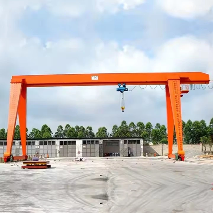

Mh Type Single Girder Gantry Crane
Products Description
SPECIALIZED VARIANTS
Light Lifting Gantry: Aluminum construction, manual travel (100kg-2 ton)
Semi-Gantry Crane: One leg, one building-mounted runway (for wall-side work)
Portable Gantry: Collapsible design with casters
Adjustable Width: Legs can be repositioned for different spans
Outdoor Heavy Duty: Corrosion protection, higher wind rating
COMPARISON: SINGLE vs. DOUBLE GIRDER GANTRY
| Factor | Single Girder | Double Girder |
|---|---|---|
| Cost | Lower (30-50% less) | Higher |
| Capacity | Up to 20 tons | Up to 500+ tons |
| Span | Up to 25m | Up to 50m+ |
| Hook Height | Lower (hoist below beam) | Higher (hoist between beams) |
| Headroom | Requires more | Requires less |
| Stability | Good for centered loads | Excellent for eccentric loads |
| Maintenance | Easier access | More complex |
| Installation | Simpler, faster | More complex |
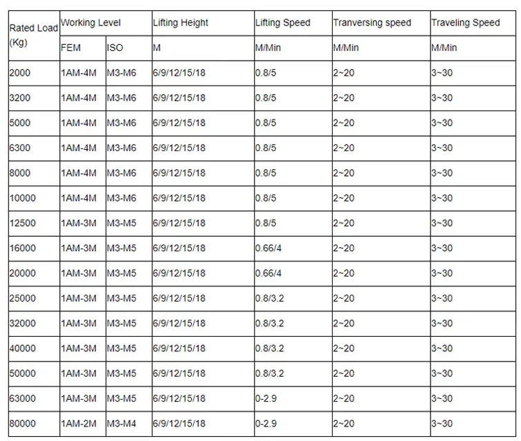
Lifting Capacity 320 tons
Span (Width) 3 - 12 meters (adjustable)
Lifting Height 3 - 10 meters
Working Class A3-A5 (light to medium duty)
Hoisting Speed 0.5 - 8 m/min (variable)
Main Beam Type Single/double girder (box-type)
Power Supply 220V/380V 3-phase or manual
Control Mode Pendant control/wireless remote
Hoist Type Electric chain hoist/wire rope hoist
Travel Drive Manual push or motorized
Corrosion Protection Hot-dip galvanized or marine-grade paint
Wind Resistance Up to Beaufort scale 6 (for outdoor use)
Operating Temp -20°C to +50°C

Pictures & Components
1. STRUCTURAL COMPONENTS (The Skeleton)
Main Girder (The Primary Beam)
Function: Primary load-bearing element that spans the working area and supports the trolley/hoist.
Types & Construction:
Standard I-Beam (Rolled Section): Most economical for spans <10m and capacities <10 tons. Material: Q235B or equivalent.
Welded Box Girder: Fabricated from steel plates (S355JR) for spans >10m or higher capacities. Provides superior torsional stiffness.
Truss Girder: Made from angle bars for very light duty or extremely long spans where weight is critical.
Key Features:
Camber: Pre-set upward deflection (typically 1/1000 of span) to compensate for deflection under load.
Running Surface: The bottom flange is often reinforced or machined smooth for trolley travel.
Connections: Drilled and machined ends for precise bolting to end carriages.

End Carriages (Leg Assemblies)
Function: Support the main girder, provide vertical stability, and house the travel wheels and drives.
Components:
Legs: Vertical columns (often box-section or built-up I-sections). Height determines hook height.
Fixed Height: Standard construction.
Telescopic: Two-section design with pin holes for height adjustment.
Top/Bottom Cross Beams: Horizontal members connecting the legs. The top beam connects to the main girder; the bottom beam stabilizes the legs and may house drive components.
End Truck (Wheel Assembly): The frame housing the wheels, axles, and bearings. Mounts to the bottom of the legs.
Runway System (The Track)
Function: Provides the travel path for the gantry crane.
Types:
Steel Rails: Standard P24 (24kg/m) or P38 (38kg/m) rails fixed to concrete sleepers or embedded in a concrete foundation.
Flat Surface (for rubber-tired): Requires a smooth, level concrete floor (minimum compressive strength 25MPa).
2. MECHANICAL & LIFTING COMPONENTS (The Muscle)
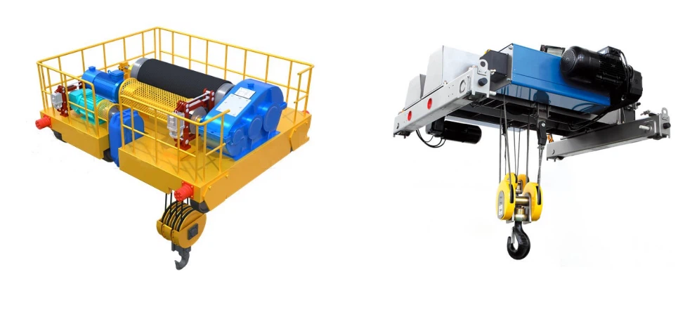
Hoist Unit
Function: The primary lifting device.
Types:
Wire Rope Electric Hoist: Standard for MH-type. Components:
Hoist Motor: Brake motor (typically 2-speed or variable frequency).
Gearbox: Multi-stage helical gear reduction.
Drum: Grooved for rope winding.
Wire Rope: 6x19 or 6x37 class, galvanized.
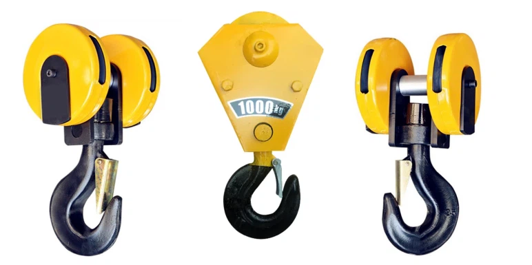
Hook Block: Swiveling hook with safety latch.
Upper/Lower Limit Switches: Mechanical or electronic.
Chain Hoist: For lighter capacities (<5 ton). Electric or hand chain.
Trolley (Hoist Carrier)
Function: Carries the hoist along the main girder.
Types:
Manual Trolley: Operator pushes/pulls the load. Simple roller or V-groove wheels.
Motorized Trolley: Electric drive for longitudinal travel. Consists of:
Trolley Frame: Steel frame with wheels.
Drive Motor & Gearbox: Small, flange-mounted.
Wheels: Double-flanged steel wheels running on bottom flange of main girder.

Travel Drive System (Gantry Motion)
Function: Moves the entire crane along the runway.
Components:
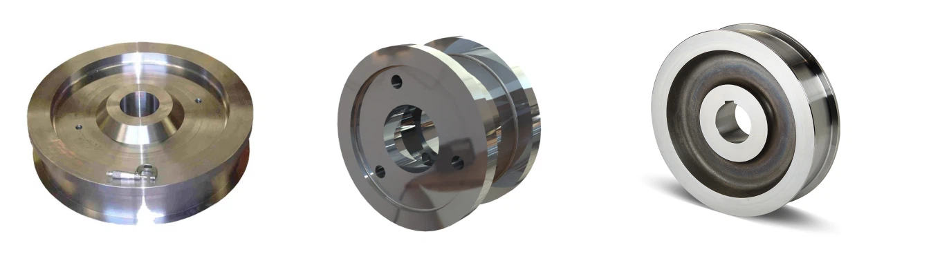
Drive Wheels: Usually 2 driven wheels (one per end carriage). Diameter: 250-500mm.
Travel Motors: Two motors (one per side) for synchronized travel, or one motor with cross-shaft.
Gearboxes: Right-angle or parallel shaft reducers.
Brakes: Motor-mounted disc or drum brakes.
Wheels & Axles
Wheels: Forged or cast steel (ZG340-640), heat-treated. Can be double-flanged (for rail) or flat (for floor running).
Axles: High-tensile steel (40Cr or equivalent), machined and heat-treated. Mounted in anti-friction bearings (spherical roller bearings).
3. ELECTRICAL & CONTROL SYSTEMS (The Nerves & Brain)
Power Supply System
Festoon System: Overhead sliding cable carrier (for longer travel). Contains power and control cables.
Cable Reel: Spring-driven or motorized drum for collecting/paying out cable.
Conductor Bar (Bus Bar): Insulated copper bars mounted along runway; crane collects power via sliding shoes. For heavy-duty, high-cycle applications.
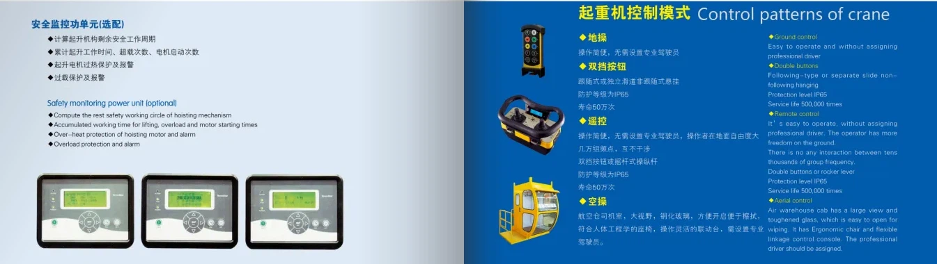
Control System
Pendant Control Station: Hanging push-button box with buttons for UP/DOWN, LEFT/RIGHT, FORWARD/BACKWARD. Connected via flexible cable.
Radio Remote Control: Transmitter (belt-pack or handheld) and receiver unit on crane. Allows operator freedom of movement.
Control Panel/Cabinet: Houses:
Contactors & Relays: For power switching.
Variable Frequency Drives (VFDs): For smooth acceleration and precise speed control (optional).
Programmable Logic Controller (PLC): For advanced control logic and diagnostics (optional).
Overload Protector: Electronic device that cuts power if load exceeds setpoint.
Safety & Limit Devices
Limit Switches:
Hoist Upper/Lower Limit: Mechanical lever-type or rotary encoder-based.
Travel Limit: Stops crane at ends of runway.
Trolley Limit: Stops trolley at ends of girder.
Emergency Stop Buttons: Mushroom-head buttons on pendant and at strategic crane locations.
Warning Devices: Buzzer or rotating beacon for motion warning.
Anti-Collision System: Infrared or ultrasonic sensors for multi-crane installations (optional).
Anemometer: Wind speed indicator/alarm for outdoor cranes (optional).


4. ACCESSORIES & AUXILIARY COMPONENTS
Lifting Attachments
Standard Hook: Forged steel, swiveling type with safety latch.
Special Hooks: C-hooks, coil hooks, etc.
Below-the-Hook Devices: Lifting beams, magnets, grabs, vacuum lifters.
Buffer & Bumper System
Rubber Buffers: Mounted on end carriages to absorb impact at runway ends.
Wheel Bumpers: Metal stops at end of rails as final travel limit.
Platforms & Ladders
Service Platform: At one end for motor and electrical maintenance access.
Access Ladder: Fixed to leg for reaching service platform.
Lighting
Work Area Lights: LED floodlights mounted on girder to illuminate lift zone.

MAINTENANCE CRITICAL COMPONENTS
| Component | Inspection Focus | Failure Signs |
|---|---|---|
| Wire Rope | Broken wires, corrosion, diameter reduction | 10% broken wires in one lay length |
| Wheels | Flange wear, tread wear, cracks | Flange thickness <80% original |
| Brakes | Lining wear, adjustment | Excessive stopping distance |
| Electrical Contacts | Pitting, burning, cleanliness | Erratic operation, overheating |
| Structural Bolts | Looseness, corrosion | Visible movement, rust |
SKETCH
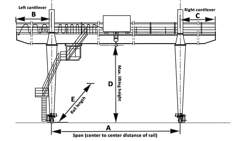
Main technical
Advantages
1. Economic Advantages (Most Compelling)
Lower Initial Investment: Costs 40-60% less than double girder cranes of equivalent capacity
Minimal Infrastructure Cost: No need for expensive overhead runway steel structures or building modifications
Reduced Installation Cost: Can be installed in 1-3 days with basic tools and minimal foundation work
Lower Operating Costs: Simpler design means fewer components to maintain; energy consumption is typically 30-50% lower than larger systems
Tax & Depreciation Benefits: Often qualifies as equipment rather than building modification
2. Installation & Flexibility Advantages
Quick Deployment: From order to operation can be as little as 2-4 weeks for standard models
No Building Modifications: Ideal for rental properties or temporary facilities
Relocatable: Can be disassembled and moved to different locations within a facility or to entirely new sites
Adaptable to Existing Spaces: Works in buildings with irregular column spacing or limited headroom
Outdoor Capable: Can operate in yards, docks, and open areas without special weather protection
3. Operational & Performance Benefits
Ease of Operation: Simple controls require minimal operator training
Space Efficiency: Uses otherwise wasted vertical space above work areas
Versatile Layout: Can serve multiple workstations along its travel path
Quick Material Flow: Reduces forklift traffic and associated congestion
Good Maneuverability: Can navigate around fixed obstacles when floor-running
4. Maintenance & Reliability
Simpler Maintenance: Fewer components and accessible design reduce maintenance complexity
Lower Spare Parts Inventory: Standardized components are readily available
Less Downtime: Modular design allows quick component replacement
Proven Technology: Uses standardized, widely available hoists and electrical components
5. Safety Benefits
Predictable Path: Fixed runway reduces risk of collisions with other equipment
Clear Visibility: Open design allows operators to maintain visual contact with loads
Reduced Ground Traffic: Minimizes pedestrian/vehicle interactions compared to mobile cranes
Inherent Stability: Four-point ground support provides stable lifting platform
Application
1. Manufacturing & Production
| Application | Typical Use | Key Requirements |
|---|---|---|
| Machine Shops | Loading/unloading lathes, mills, press brakes | 1-10 tons, 6-15m span, precise positioning |
| Welding/Fabrication | Positioning plates, structures for welding | Rotating hooks, good maneuverability |
| Assembly Lines | Component placement in vehicle/machine assembly | 2-5 tons, smooth variable speed control |
| Maintenance Bays | Engine/component removal, equipment repair | 3-15 tons, adjustable height capability |
2. Warehousing & Logistics
| Application | Typical Use | Key Requirements |
|---|---|---|
| Loading Docks | Truck/trailer loading/unloading | 2-10 tons, quick cycle times, outdoor rated |
| Storage Yards | Stacking pallets, materials, equipment | 5-20 tons, 15-25m span, weatherproof |
| Rail Car Loading | Loading/unloading bulk materials from rail cars | Material-specific attachments (coil hooks, etc.) |
| Container Handling | Small container operations (1-2 TEU) | 10-20 tons, spreader attachments |
3. Construction & Infrastructure
| Application | Typical Use | Key Requirements |
|---|---|---|
| Precast Concrete | Handling concrete panels, beams, pipes | 5-20 tons, rotating capability, precise control |
| Steel Erection | Positioning structural steel members | 5-15 tons, good outdoor performance |
| Equipment Maintenance | Servicing excavators, bulldozers, trucks | 10-20 tons, adjustable width for different vehicles |
| Temporary Sites | Bridge repair, plant shutdown maintenance | Portable designs, quick assembly |
4. Specialized Applications
| Application | Typical Use | Key Requirements |
|---|---|---|
| Scrap Yards | Light scrap handling, sorting operations | 3-10 tons, magnet or grapple attachments |
| Agricultural | Equipment repair, feed handling, hay bales | 2-5 tons, wide spans for barns, dust protection |
| Marine/Shipyards | Small boat maintenance, engine handling | Corrosion protection, spark-resistant options |
| Event Production | Stage equipment, lighting rigs, sets | Portable, lightweight, quiet operation |
Crane production process
The production of an MH Type Single Girder Gantry Crane is a streamlined but precise manufacturing process that transforms raw materials into a reliable lifting system. Unlike the complex fabrication of double girder bridge cranes, this process emphasizes efficiency, standardization, and cost-effectiveness while maintaining essential quality.
Here is the complete production workflow, from order to shipment:
PHASE 1: ENGINEERING & PLANNING (1-3 Days)
1.1 Design & Detailing
Order Review: Technical team reviews client specifications (capacity, span, lift height, duty cycle, control type).
CAD Modeling & Analysis:
Standard models are pulled from a library and modified.
Structural Calculation: Basic stress analysis for main girder deflection (usually limited to ≤Span/750 under full load).
Component Selection: Standard hoist models, motors, and electrical components are selected from approved vendor lists.
Drawing Generation:
General Arrangement (GA) drawings for client approval.
Detailed fabrication drawings for the workshop.
Electrical schematic and wiring diagrams.
1.2 Bill of Materials (BOM) & Scheduling
BOM Creation: Lists all raw materials (steel plates, beams) and purchased components (hoist, wheels, motors, electrical panels).
Production Scheduling: Job is slotted into the production line, typically following a flow-shop model.
PHASE 2: MATERIAL & COMPONENT PROCUREMENT (Parallel to Fabrication)
Raw Materials: Steel plates (S355JR) and sections (I-beams, channels) are ordered from mill or stock.
Purchased Components: Standard items are sourced, often from stock:
Complete Hoist Unit: Wire rope hoist (e.g., from CM, Kito, Demag).
Drive Package: Travel motors, gearboxes, and brakes.
Electrical Kit: Control pendant, contactors, limit switches.
Mechanical Parts: Wheels, axles, bearings.
PHASE 3: CORE FABRICATION PROCESS (5-10 Days)
3.1 Main Girder Fabrication
This is the most critical fabrication step.
Step A: Material Preparation
For I-Beam Girders: Standard rolled I-beam (e.g., GB/T 706) is cut to length.
For Welded Box Girders:
Plates are shot-blasted and primed.
Web and flange plates are cut to size using CNC plasma cutting.
Step B: Assembly & Welding
Jigging: Plates are placed in a large assembly jig to ensure straightness and correct geometry.
Welding: Main longitudinal welds are made using Submerged Arc Welding (SAW) for deep penetration and quality. Stiffeners are welded inside using MAG welding.
Camber Induction: For spans >10m, a slight upward camber (pre-deflection) is often induced during welding by positioning the jig.
Step C: Machining & Finishing
End Machining: Girder ends are milled square to ensure perfect fit with end carriages.
Drilling: Bolt holes for end carriage connections are drilled using a radial drill.
Running Surface Prep: The bottom flange (trolley runway) is ground smooth if needed.
3.2 End Carriage Fabrication
Leg Fabrication: Box sections are welded from steel plate. Critical points are the connections to the top cross beam and the wheel axle housing.
Cross Beam Fabrication: Top and bottom connecting beams are fabricated.
Wheel Assembly Build:
Axles are pressed into wheels with heavy-duty bearings.
The complete wheel block is assembled into the end truck frame.
Drive motors and gearboxes are mounted for powered travel.
PHASE 4: SUB-ASSEMBLY & TRIAL FIT-UP (1-2 Days)
Dry Assembly: The main girder is bolted to the two end carriages on the shop floor.
Alignment Check:
Squareness: Diagonal measurements are taken to ensure the frame is square (tolerance: ±5mm).
Level: The main girder is checked for level along its length.
Wheel Alignment: All four (or more) wheels are checked to be in the same plane.
Purpose: This critical step identifies any fit-up issues before painting, when corrections are still easy.
PHASE 5: SURFACE TREATMENT (2-3 Days)
Disassembly: The crane is taken apart into main components (girder, two end carriages).
Abrasive Blasting: All components are blasted to Sa 2.5 standard to remove mill scale and rust, creating a surface profile for paint adhesion.
Painting:
Priming: Zinc-rich epoxy primer is applied (70-80μm) for corrosion protection.
Intermediate Coat: Epoxy paint layer (80-100μm) for build and chemical resistance.
Top Coat: Polyurethane topcoat (50-60μm) in the client's color. This provides UV and weather resistance.
Marking: Component identification numbers and lifting points are stenciled.
PHASE 6: FINAL ASSEMBLY, INTEGRATION & TESTING (3-5 Days)
6.1 Mechanical Re-Assembly
Painted components are bolted together using high-strength friction-grip bolts (Grade 10.9).
Hoist and Trolley Mounting: The purchased hoist unit is mounted onto its trolley (motorized or manual), and the complete assembly is placed on the girder's running flange.
6.2 Electrical System Integration
Panel Wiring: Control panel is wired according to schematics.
On-Board Wiring: Motors, limit switches, pendant stations, and warning devices are wired.
Power Feed Installation: Festoon system or cable reel is mounted.
PLC Programming (if applicable): Basic logic for control and safety interlocks is loaded.
6.3 Factory Acceptance Testing (FAT) - MANDATORY
Visual Inspection: Check for completeness, paint quality, and proper labeling.
No-Load Functional Test:
Operate all motions: Hoist up/down, trolley travel, gantry travel.
Verify direction, brake function, and limit switch operation.
Load Testing (Per ISO 8686-1/FEM 9.755):
Static Load Test: Lift a test weight equal to 125% of Rated Capacity. Hold for 10 minutes. Inspect for permanent deformation, check brake holding.
Dynamic Load Test: Lift and operate all motions with 110% of Rated Capacity.
Safety Device Verification: Test all emergency stops, overload limiter (if equipped), and audio/visual alarms.
Electrical Tests: Insulation resistance, earth continuity, phase sequence.
PHASE 7: DISASSEMBLY, PACKING & SHIPPING (1-2 Days)
Strategic Disassembly: Crane is broken down into shipment-friendly packages:
Package 1: Main Girder
Package 2 & 3: Left and Right End Carriages (with wheels attached)
Package 4: Hoist & Trolley unit
Package 5: Electrical Panels and accessories box
Packaging: Components are wrapped in plastic and secured in wooden crates or on timber skids. Critical machined surfaces are protected.
Documentation: Final packing list, test certificates, assembly manual, and parts manual are prepared for shipment.

Workshop view:
The company has installed an intelligent equipment management platform, and has installed 310 sets (sets) of handling and welding robots. After the completion of the plan, there will be more than 500 sets (sets), and the equipment networking rate will reach 95%. 32 welding lines have been put into use, 50 are planned to be installed, and the automation rate of the entire product line has reached 85%.




Hot Tags: mh type single girder gantry crane, China mh type single girder gantry crane manufacturers, suppliers, factory, Single Girder Gantry Crane, Gantry Crane, Electric Hoist Single Girder Gantry Crane
You Might Also Like


Send Inquiry