


Rubber Tyred Double Girder Gantry Crane
Products Description
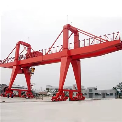
What is a Rubber Tyred Double Girder Gantry Crane?
It is a large gantry crane where the entire structure-comprising two main girders supported by legs at each end-runs on rubber tires instead of fixed rails embedded in the ground. Each leg is mounted on a bogie (wheel assembly) with multiple tires, powered by independent drive motors. It is often self-propelled and may require a clear, paved, and level operating surface.
Disadvantages and Considerations
1. Higher Operating Cost (vs. Electric Overhead Cranes): Diesel-powered units have significant fuel and maintenance costs for engines and hydraulic systems.
2. Complex Maintenance: The tire, bogie, and steering systems require regular maintenance (tire pressure, alignment, wear).
3. Surface Dependency: Performance is entirely dependent on the quality, levelness, and bearing capacity of the ground surface. Soft ground can be problematic.
4. Lower Precision in Travel: Slightly less precise than a rail-mounted crane, especially on uneven surfaces, though modern control systems compensate well.
5. Higher Initial Cost: Typically more expensive than a comparable single girder gantry or a fixed-base crane due to its complex drive and steering systems.
Comparison with Rail-Mounted Gantry Cranes (RMG)
| Feature | Rubber Tyred Gantry (RTG) | Rail-Mounted Gantry (RMG) |
|---|---|---|
| Mobility | Free-ranging, omnidirectional movement. | Confined to fixed rail tracks. |
| Site Prep | Requires a paved, level surface. Lower initial civil cost. | Requires heavy foundation and rail installation. Higher initial civil cost. |
| Precision | Good, but can be affected by ground conditions. | Excellent, fixed path allows for automated, highly repeatable positioning. |
| Operating Cost | Higher (fuel, tire wear, more complex drives). | Lower (electric power, simpler wheel/rail maintenance). |
| Ideal For | Dynamic, changing layouts; multiple work zones; outdoor yards. | Repetitive, high-density storage; automated systems; long-term fixed operations. |
| Capacity/Stability | Very High (uses outriggers for lifting). | Extremely High (inherently stable on rails). |
Conclusion
The Rubber Tyred Double Girder Gantry Crane is the premier choice for heavy lifting applications that demand both massive capacity and free-roaming mobility. It eliminates the constraint of fixed rails, offering unparalleled flexibility to cover vast, open areas and adapt to changing site layouts. While it comes with higher operational complexity and surface requirements, its ability to bring heavy-lift capability directly to where the load is-whether in a port yard, on a construction site, or a sprawling fabrication facility-makes it an indispensable tool in heavy industry and logistics.
Lifting Capacity 320 tons
Span (Width) 3 - 12 meters (adjustable)
Lifting Height 3 - 10 meters
Working Class A3-A5 (light to medium duty)
Hoisting Speed 0.5 - 8 m/min (variable)
Main Beam Type Single/double girder (box-type)
Power Supply 220V/380V 3-phase or manual
Control Mode Pendant control/wireless remote
Hoist Type Electric chain hoist/wire rope hoist
Travel Drive Manual push or motorized
Corrosion Protection Hot-dip galvanized or marine-grade paint
Wind Resistance Up to Beaufort scale 6 (for outdoor use)
Operating Temp -20°C to +50°C

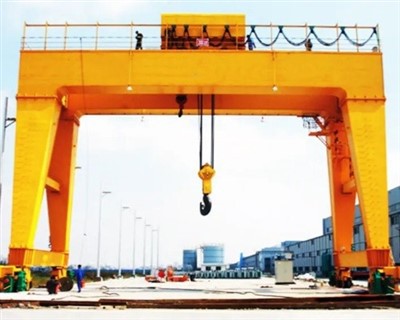
Pictures & Components
The Rubber Tyred Double Girder Gantry Crane (RTG) is a complex machine where each component plays a critical role in its mobility, strength, and safety. Understanding these parts is key to appreciating its operation and maintenance.
Here is a detailed breakdown of its major components, organized by system.
1. Main Structural Components (The Skeleton)
These form the primary load-bearing frame.
Main Girders (Double): Two heavy-duty, fabricated steel beams that span the width of the crane. They are designed with camber (upward pre-bend) to counteract deflection under load. They support the trolley and distribute the load to the legs.
Legs / End Frames: Two vertical structures (one at each end) that support the main girders and transfer the entire load to the bogies and tires. They house or support the drive machinery, operator's cab, and often the main power source.
Trolley Frame: The steel structure that runs on rails along the top of the main girders. It carries the hoist unit and all trolley travel machinery.
Bogie Frames: The heavy, wheeled substructures attached to the bottom of each leg. They contain the axles, wheels, tires, and often the travel drive motors and steering mechanisms.

2. Mobility & Running System (The "Rubber Tyred" Foundation)
This system defines the crane's unique flexibility.
Rubber Tires: Large, high-capacity pneumatic (or sometimes solid) tires. They are arranged in sets (e.g., 4x2, 8x2 per bogie) to distribute ground pressure. Key specifications include ply rating, tread pattern, and inflation pressure, which are critical for stability and surface protection.
Wheels & Axles: Robust axles and wheel hubs that connect the tires to the bogie frame. They are built to withstand immense radial and axial loads.
Travel Drive Units: Electric motors coupled with high-torque reduction gearboxes, mounted on the bogies to drive the wheels. Typically, multiple motors are used (e.g., one per wheel or axle) and are synchronized electronically.

Steering System: A complex hydraulic or electromechanical system that turns the bogies (and sometimes individual axles). It enables multiple steering modes:
90° (Crab Steering): All wheels turn in the same direction for sideways movement.
Circle (Pivotal): Wheels on each bogie turn opposite directions for tight rotation.
Diagonal: For traveling at an angle across the yard.
Two-Wheel / Four-Wheel: Standard forward/reverse steering.
Outriggers / Stabilizers: Hydraulic cylinders that extend vertically from the legs down to ground pads. They are crucially deployed before lifting to:
Stabilize the crane by taking the load off the tires.
Distribute the concentrated load to the ground.
Prevent tire deformation and potential bounce or sway.

3. Lifting & Hoisting System (The Workhorse)
This is the core lifting mechanism, mounted on the trolley.
Hoist Unit: The complete assembly for vertical lifting. It consists of:
Hoist Motor: A high-power electric motor (often with a built-in brake).
Reducer (Gearbox): A multi-stage helical gearbox to reduce motor speed and dramatically increase output torque.
Wire Rope Drum: A machined steel drum onto which the wire rope is wound in multiple layers.
Wire Rope: High-strength, non-rotating steel cable, sized for the crane's capacity.
Hook Block: The assembly at the end of the rope, featuring a heavy-duty swivel hook, sheaves (pulleys), and bearings. May include a safety latch.

Trolley Travel System: The mechanism that moves the hoist laterally across the girders. Includes:
Trolley Drive Motors & Gearboxes.
Trolley Wheels: Running on rails fixed to the top of the main girders.
Rail & Rail Clamps (optional): Clamps can secure the trolley in position during transport or in high winds.

4. Power & Control System (The Nerve Center)
Prime Power Source:
Diesel Generator Set: The most common for full autonomy. A large diesel engine drives an AC generator to produce power for all electric drives.
Electric Cable Reel: For use in defined areas. A motorized reel pays out/collects a heavy-duty power cable connected to a shore-side substation.
Hybrid System: Combines a smaller diesel generator with a battery bank for peak shaving, silent operation, or emission-free travel.
Control Cabin: An enclosed, often air-conditioned operator's cab. It is usually located high on one leg for optimal visibility and may be elevatable. Contains:
Master controllers (joysticks/levers)
Instrumentation (load indicator, engine gauges)
Alarm panels and visualization screens.

Radio Remote Control System: An alternative to the cab. The operator carries a portable, weatherproof transmitter, allowing for safer and more flexible positioning on the ground.
Electrical Control Panels: Cabinets containing:
Variable Frequency Drives (VFDs): For smooth, precise control of all travel and hoist motors (acceleration, deceleration, speed regulation).
Programmable Logic Controller (PLC): The "brain" that coordinates all motions, safety interlocks, and steering modes.
Contactors, Circuit Breakers, and Transformers.

5. Safety & Ancillary Components (Essential Protections)
Load Moment Indicator (LMI) / Rated Capacity Limiter (RCL): The most critical safety device. A computer system that monitors hook load (via a sensor) and boom angle/radius, calculating the lifting moment. It warns the operator and can automatically cut off dangerous movements.
Anti-Collision Systems: Uses laser, radar, or GPS to detect obstacles or other RTGs in the area and provides warnings or automatic stops.
Limit Switches: Mechanical or proximity switches to prevent over-travel of the hoist (upper/lower limit), trolley, and gantry travel.

Anemometer & Wind Alarm: Measures wind speed. Provides audible/visual warnings and may automatically disable crane functions in high winds.
Fire Suppression System: Especially important in the engine/generator compartment.
Lighting & Signaling: Strobe lights, travel lights, and audible travel alarms for safety in low visibility or to alert ground personnel.
Bumpers & Guards: Rubber or polyurethane bumpers on the legs to absorb minor impacts.

SKETCH

Main technical

Advantages
1. Ultimate Mobility & Flexibility
Rail-Free Operation: The defining advantage. Unlike fixed rail gantries, RTGs operate on standard paved surfaces, eliminating the need for expensive embedded track systems.
Omnidirectional Steering: Advanced steering systems enable crab (sideways), pivotal (circle), and diagonal movement, allowing precise positioning in congested areas.
Site Adaptability: Can be easily redeployed across different work zones or even between project sites, offering unmatched operational flexibility.
2. Superior Lifting Performance
High Capacity & Stability: The double girder design provides exceptional rigidity, minimizing deflection under load. Capacities typically range from 20 to over 500 tons.
Excellent Hook Height: Hoist mounted on top of girders maximizes lift height-critical for stacking or handling tall cargo.
Smooth & Precise Control: Modern RTGs utilize Variable Frequency Drives (VFDs) and PLC control for jerk-free acceleration, precise load spotting, and anti-sway capabilities.
3. Cost-Effective Infrastructure
Lower Initial Civil Works: Requires only a properly compacted and leveled asphalt or concrete pad, avoiding the high cost of rail beds, foundations, and associated earthworks.
Reduced Installation Time: Can be commissioned rapidly after surface preparation, speeding up project timelines.
Scalable Coverage: A single RTG can service multiple storage lanes or work areas, reducing the need for multiple fixed cranes.
4. Operational Safety & Stability
Integrated Outriggers: Hydraulic stabilizers deploy during lifts, transferring load directly to the ground, eliminating tire compression and ensuring rock-solid stability.
Advanced Safety Systems: Standard features include:
Load Moment Indicator (LMI) with automatic cut-off
Anti-Collision systems (laser/GPS)
Wind speed monitoring with automatic shutdown
Tilt sensors for ground condition monitoring
Enhanced Visibility: Elevated operator cabins provide panoramic views, while radio remote control allows ground-level operation in hazardous zones.
5. Environmental & Operational Adaptability
Multiple Power Options:
Diesel-Electric: Full autonomy for remote yards.
Cable Reel/Electric: For eco-friendly factory operations.
Hybrid/Battery: Emerging technology reducing emissions and noise.
All-Weather Capability: Designed for outdoor operation with corrosion protection, lighting, and climate-controlled cabs.
Application
1. Ports & Intermodal Terminals
Break-Bulk & Project Cargo: Ideal for handling heavy machinery, transformers, wind turbine components, and steel structures in general cargo terminals.
Container Handling (Specialized): While smaller than mega-port RTGs, double girder versions handle out-of-gauge containers, heavy equipment, and Ro-Ro cargo.
Barge & Feeder Vessel Operations: Mobile along quaysides to service multiple vessels.
2. Heavy Fabrication & Industrial Yards
Steel Service Centers: Handling steel coils, plates, and beams in outdoor storage yards. Can service multiple storage bays from a single travel aisle.
Shipbuilding & Offshore: Moving large hull sections, modules, and offshore platform components across sprawling fabrication yards.
Heavy Machinery Manufacturing: For plants with extensive outdoor assembly areas (mining trucks, agricultural equipment, locomotives).
3. Construction & Infrastructure Projects
Bridge Construction: Erecting precast concrete girders and steel trusses. Mobility allows the crane to "walk" the bridge length during construction.
Power Plant Construction: Handling turbines, generators, heat exchangers, and pressure vessels at thermal, hydro, and nuclear sites.
Industrial Plant Erection: Installing process equipment, reactors, and large structural elements in refinery and chemical plant construction.
4. Logistics & Warehousing
Heavy Equipment Storage Yards: For military depots, agricultural equipment dealers, and mining equipment logistics centers.
Precast Concrete Plants: Handling and storing large precast elements (wall panels, beams, tunnel segments).
Forest Products: Handling log packages and lumber bundles in sawmill yards.
5. Specialized Applications
Disaster Recovery & Heavy Salvage: Rapidly deployable for clearing wreckage or recovering heavy machinery.
Event Staging: Installing large stage components, concert roofs, and exhibition structures.
Aerospace: Moving large aircraft components between buildings or to test facilities.
Crane production process
The production of a Rubber Tyred Double Girder Gantry Crane is a sophisticated, multi-stage engineering project that blends heavy steel fabrication, precision mechanical assembly, and complex electrical integration. Unlike fixed cranes, the RTG's mobility systems add significant complexity to its manufacture.
Phase 1: Engineering & Design (The Digital Blueprint)
This phase defines the crane's capabilities and ensures all components will function as an integrated system.
Client Specification Analysis: Engineers review detailed requirements: Capacity (e.g., 100 tons), Span (e.g., 30m), Lifting Height, Duty Class (A5-A7 for heavy cycling), and operational environment (e.g., seaport, steel mill).
Structural Finite Element Analysis (FEA): Advanced CAD/CAE software simulates stress, deflection, dynamic loading, and wind effects on the main girders, legs, and bogie frames. This ensures structural integrity under all operational scenarios.
Mobility & Steering System Design: A critical differentiator from fixed cranes. Engineers design the bogie configuration (wheel arrangement: 4x2, 8x2, etc.), steering kinematics (calculations for crab, circle, and diagonal modes), and hydraulic or electromechanical actuation.
Electrical & Control Systems Design: Creating schematics for power distribution, drive synchronization, PLC logic, and safety interlocks. Special attention is given to load sharing between multiple travel motors and steering coordination.
Bill of Materials (BOM) Generation: A comprehensive list of all raw materials and specialized purchased components.
Phase 2: Procurement of Specialized Components
RTGs require unique, high-value components not found in standard overhead cranes.
Rubber Tires & Rims: Heavy-duty, high-ply pneumatic tires (e.g., 14.00-25, 18.00-25) with specific load ratings. Often sourced from specialized industrial tire manufacturers.
Bogie & Steering Assemblies: Complete steerable bogie units, including axles, hubs, kingpins, and hydraulic steering cylinders or electric rack-and-pinion systems. May be manufactured in-house or sourced from specialized suppliers.
Power Pack: Diesel Generator Set (engine + alternator) of appropriate kW rating, or components for electric cable reel systems or hybrid/battery packs.
Specialized Drives: High-torque, low-speed travel drive motors with planetary gear reducers, often featuring integrated fail-safe brakes.
Safety & Control Electronics: Load Moment Indicator (LMI) system with sensors, anti-collision systems (laser/GPS), and steering angle sensors.
Phase 3: Heavy Steel Fabrication & Machining
A. Main Girder Fabrication
CNC Cutting: Main web and flange plates are precision-cut using CNC plasma or oxy-fuel cutting.
Sub-assembly Welding: Internal stiffeners (diaphragms) are welded to the web plates in automated welding stations.
Girder Box Assembly: The web and flanges are assembled into a box-section girder on massive, computer-controlled jigs that ensure correct camber (pre-set upward curve).
Automated Welding: Critical main seams are welded using Submerged Arc Welding (SAW) for deep penetration and superior quality. The process is often performed simultaneously on both sides to control distortion.
Stress Relieving: The complete girders undergo Vibratory Stress Relief (VSR) or thermal annealing in a large furnace to eliminate internal welding stresses.
Precision Machining: The girder ends and trolley rail mounting surfaces are machined on large planer-millers or gantry mills to ensure perfect flatness and parallelism.
B. Leg & Bogie Frame Fabrication
Legs are fabricated as welded box sections with reinforced connection points for the girders and bogies.
Bogie frames are made from extremely thick steel plate to handle massive bending moments. They are drilled and machined to precise tolerances for axle and steering component mounting.
Phase 4: Mechanical Assembly & Integration
This phase transforms fabricated parts into functional systems.
Bogie Assembly: Tires, axles, bearings, and travel drive units (motor + gearbox) are mounted onto the bogie frame. The steering mechanism (hydraulic rams or motor-driven gears) is installed and tested for free movement.
Leg-Bogie Integration: The bogies are connected to the legs. Hydraulic outrigger cylinders are installed on the legs.
Bridge Assembly: The two main girders are lifted and precisely aligned on temporary supports. They are connected by end ties and the trolley rails are bolted down with laser-leveled alignment.
Trolley Assembly: The trolley frame is built, and the main hoist (drum, motor, gearbox, sheaves) and trolley travel drives are installed. The complete trolley is then placed on the bridge rails.
Phase 5: Electrical & Hydraulic Systems Installation
Cable Tray & Conduit Installation: Extensive trays are mounted along girders and legs for power and control cables.
Drives & Control Panel Installation: VFD cabinets for all motions, the main PLC control panel, and the engine control panel (for diesel units) are mounted in protected enclosures.
Wiring & Piping: Hundreds of meters of power, control, and feedback cables are pulled and terminated. Hydraulic lines for steering and outriggers are installed, fitted, and pressure-tested.
Sensor Installation: Load cells (for the LMI), wind anemometers, limit switches, bump sensors, and steering angle encoders are fitted and connected.
Operator Interfaces: The control cabin (with joysticks, screens, and seats) is installed, or radio remote control systems are configured.
Phase 6: Surface Treatment & Painting
Abrasive Blasting: The entire structure is shot-blasted to SA 2.5 (Near-White Metal) cleanliness for optimal paint adhesion.
Multi-Coat Painting: Applied in controlled, ventilated paint booths:
Primer: Zinc-rich epoxy primer for cathodic corrosion protection.
Intermediate Coat: High-build epoxy for barrier protection.
Topcoat: Polyurethane enamel for UV resistance and color (often standard safety yellow/black).
Specialized Coatings: Undercarriage and areas prone to chemical splash may receive extra-thick or specialized coatings.
Phase 7: Pre-Delivery Factory Acceptance Testing (FAT)
Testing is more comprehensive than for fixed cranes due to the mobility systems.
Structural & Visual Inspection: Verification of all dimensions, weld quality, and assembly.
Functional Tests (No-Load):
Steering Mode Tests: Verification of all steering modes (90°, circle, diagonal, etc.).
All Motions Test: Hoisting, trolley, and gantry travel in all directions and speeds.
Outrigger Operation: Cycle testing of hydraulic stabilizers.
Load Testing:
Static Load Test: Hoist 125% of rated capacity, hold for 10+ minutes. Inspect for permanent deformation. Outriggers must be deployed.
Dynamic Load Test: Operate all motions at 110% rated capacity.
Safety System Tests:
LMI/RCL Calibration: Verify accuracy and automatic functions at multiple radii.
Anti-Collision System Test.
Emergency Stop & Limit Switch Verification.
Tilt Alarm Test (simulating unstable ground).
Phase 8: Dismantling, Preservation & Shipping
The crane is systematically dismantled into major modules: Girders, Legs (with bogies attached), Trolley, Power Pack, and Control Panels.
All exposed hydraulic ports and machined surfaces are sealed and preserved.
Components are specially crated or mounted on transport frames for ocean or heavy haulage road shipment.
Phase 9: Site Erection & Commissioning (Post-Delivery)
Foundation Check: Verification of ground bearing capacity and levelness of the operating area.
Mechanical Re-assembly: Components are reconnected using high-strength bolts.
System Re-connection: Electrical and hydraulic lines are re-connected.
Final Site Testing: Re-testing of functions, steering calibration on the actual surface, and final LMI calibration with certified test weights.

Workshop view:
The company has installed an intelligent equipment management platform, and has installed 310 sets (sets) of handling and welding robots. After the completion of the plan, there will be more than 500 sets (sets), and the equipment networking rate will reach 95%. 32 welding lines have been put into use, 50 are planned to be installed, and the automation rate of the entire product line has reached 85%.


Hot Tags: rubber tyred double girder gantry crane, China rubber tyred double girder gantry crane manufacturers, suppliers, factory
You Might Also Like


Send Inquiry