


Mg-u Type Double Girder Gantry Cranes
Product Introduction
DEFINITION & CORE CONCEPT
MG-u Type Double Girder Gantry Cranes are a standardized series of high-capacity, universal gantry cranes designed according to specific industrial standards (typically Russian GOST or similar Eastern European norms). The designation breaks down as:
MG = Mostovoy Gantry (Bridge Gantry)
u = Universal/General Purpose
Double Girder = Two main load-bearing beams
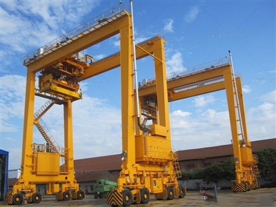
These are rail-mounted, outdoor gantry cranes with legs that run on ground-level tracks, forming a movable "gate" structure capable of spanning large work areas without requiring building support.
DEFINITION & CORE CONCEPT
MG-u Type Double Girder Gantry Cranes are a standardized series of high-capacity, universal gantry cranes designed according to specific industrial standards (typically Russian GOST or similar Eastern European norms). The designation breaks down as:
MG = Mostovoy Gantry (Bridge Gantry)
u = Universal/General Purpose
Double Girder = Two main load-bearing beams
These are rail-mounted, outdoor gantry cranes with legs that run on ground-level tracks, forming a movable "gate" structure capable of spanning large work areas without requiring building support.
Typical Technical Parameters
Lifting Capacity: 20–500 t
Span: 18–50 m (customizable)
Lifting Height: 10–30 m
Working Duty: A5–A7
Control Mode: Cabin / Pendant / Remote

Pictures & Components
1. MAIN METAL STRUCTURE COMPONENTS
1.1 Bridge (Main) Structure
Main Girders (2x): Primary load-carrying beams.
Construction: Welded box girders with internal stiffening plates/diaphragms
Material: S355JR steel (or equivalent GOST St3/St4 steel)
Features: Cambered for deflection compensation (typically L/1000)
End Connections: Machined surfaces with high-strength bolt connections to end frames
Girder Connecting Beams: Transverse beams at each end connecting the two main girders
Trolley Rails: P43 or QU-type rails mounted on top of main girders
Rail Fasteners: Bolt-type or welded clips to secure rails
Rail Joints: Ground smooth for seamless trolley travel
1.2 End Frames (Leg Structures)
Rigid Legs (2x): Vertical or slightly inclined columns
Construction: Box section or lattice design
Bracing: Diagonal cross-bracing for stability
Ladder/Access: Fixed ladders with safety cages for maintenance access
Leg-to-Girder Connection: High-strength bolted flange connection with alignment pins
Machined Pads: Precision surfaces for accurate girder mounting
1.3 End Carriages (Travel Bogies)
Travel Bogie Frames: Structural frames housing wheels and drives
Wheel Assemblies (per bogie):
Wheels: Forged steel wheels with double flanges
Wheel Axles: Solid steel shafts with keyways
Bearings: Tapered roller bearings in sealed housings
Wheel Covers: Protective covers against debris
Buffer Plates: Mounted at ends of end carriages
Rail Sweepers: Angled plates ahead of wheels to clear debris from rails
 .
.
2. HOISTING MECHANISM COMPONENTS
2.1 Hoist Assembly (Mounted on Trolley)
Hoist Motor: AC induction motor (wound rotor or squirrel cage)
Power: 7.5-150 kW depending on capacity
Insulation: Class F or H for thermal endurance
Mounting: Foot-mounted with flexible coupling
Hoist Gearbox: Two-stage helical gear reducer
Gear Ratio: Typically 40:1 to 80:1
Housing: Cast iron or welded steel
Lubrication: Oil bath with sight glass
Brake System:
Main Brake: Electromagnetic thruster brake on high-speed shaft
Emergency/Safety Brake: Spring-loaded mechanical brake
Brake Wheel/Lining: Replaceable friction material
Rope Drum:
Construction: Welded steel with machined grooves
Rope Layers: Designed for multiple rope layers
Drum Ends: Flanged with rope anchor points
Drum Shaft: Supported by heavy-duty bearings
Rope Guide: Helical groove follower to ensure proper spooling
2.2 Rope System
Wire Rope: 6x36WS or 6x19S construction
Diameter: 11-32mm depending on capacity
Grade: 1770 N/mm² or higher
Lubrication: Pre-lubricated during manufacture
Rope Anchorage: Wedge-type or clamp-type anchors on drum
Sheaves/Pulleys:
Head Sheave: Grooved cast steel sheave on trolley frame
Equalizing Sheaves: For multiple fall reeving
Bearings: Sealed roller bearings in each sheave
Hook Block:
Hook: Forged steel hook with safety latch
Swivel: Thrust bearing assembly for 360° rotation
Sheave Assembly: Multiple sheaves for rope reeving
Load Cell Pocket: (Optional) for weight measurement

3. TROLLEY COMPONENTS
3.1 Trolley Frame
Main Frame: Welded steel frame with cross-bracing
Wheel Assemblies (4 or 8 wheels):
Wheels: Double-flanged steel wheels
Axle Boxes: Cast steel housings with bearings
Wheel Balancing: Dynamic balancing performed
Bumpers: Rubber or spring buffers at trolley ends
Skirt Plates: Safety plates around moving parts
3.2 Trolley Drive Mechanism
Drive Motor: AC motor with brake
Drive Gearbox: Helical gear reducer
Drive Wheels: One or two driven wheels
Coupling: Flexible or gear-type coupling
3.3 Trolley Platforms & Walkways
Maintenance Platform: Grid steel platform around mechanisms
Handrails: 1m high with kick plates
Access Ladder: From main girder walkway


4. GANTRY TRAVEL MECHANISM
4.1 Long Travel Drives
Travel Motors (2 or 4 total):
Power: 3-30 kW each
Mounting: Vertical or horizontal configuration
Brakes: Spring-set brakes on each motor
Travel Gearboxes:
Type: Parallel shaft or right-angle gear reducers
Mounting: Directly to bogie frame
Drive Wheels: Flanged wheels keyed to gearbox output
Coupling: Gear-type or rigid coupling
4.2 Rail System Components
Crane Rails: QU70, QU80, QU100, or P43/P50 rails
Rail Fasteners: Fish plates, bolts, and clips
Rail Pads: Neoprene or steel pads under rails
Rail Joints: Welded or bolted with smooth transition
Rail Anchors: To prevent rail creeping
Rail Lubricators (Optional): Automatic flange lubricators
 |
 |
 |
5. ELECTRICAL SYSTEM COMPONENTS
5.1 Power Supply System
Conductor System (One of these):
Conductor Bars: Enclosed copper or steel conductor bars
Festoon System: Cables in festoon carriers
Cable Reel: Spring- or motor-driven cable drum
Collector Shoes/Carriages: Current collection devices
Main Circuit Breaker: Air circuit breaker in main panel
Disconnect Switch: Manual isolation switch
5.2 Control & Protection
Control Panel:
Contactors: AC3 duty contactors for motor control
Overload Relays: Thermal or electronic motor protection
Timer Relays: For acceleration/deceleration control
Terminal Blocks: DIN-rail mounted with labeling
Operator's Cabin:
Cabin Structure: Welded steel with safety glass
Control Devices: Master controllers or joysticks
Instrumentation: Ammeters, indicator lights
Heating/AC: Climate control systems
Seat: Adjustable operator seat
Resistor Banks (for wound rotor motors):
Resistor Grids: Cast iron or steel grid resistors
Enclosure: Ventilated steel cabinet
Mounting: Isolated from structure
5.3 Safety & Limit Devices
Limit Switches:
Hoist Upper/Lower: Rotary cam or lever type
Trolley Limits: At both ends of girder
Gantry Travel Limits: At rail ends
Overload Protection:
Load Cell (electronic) or Load Limiter (mechanical)
Display Unit: In operator's cabin
Anti-Collision System (for multiple cranes):
Sensors: Ultrasonic or laser distance sensors
Control Unit: Programmable controller
Emergency Stop Buttons:
Cabin: Red mushroom buttons
Local Stations: At strategic locations on structure
 |
 |
 |
6. SAFETY & AUXILIARY COMPONENTS
6.1 Safety Equipment
Audible Warning: Electric horn or siren
Visual Warning: Rotating beacon lights (red/amber)
Wind Monitoring (for outdoor):
Anemometer: Cup-type with transmitter
Display: Wind speed indicator in cabin
Alarm: Audio-visual alarms at set points
Rail Clamps:
Manual or Hydraulic: For parking in high winds
Activation: Manual lever or electric pump
Fire Extinguishers: CO₂ or dry powder type in cabin and on structure
First Aid Kit: Standard industrial first aid supplies
6.2 Maintenance & Access Features
Walkways: Full-length catwalks along main girder
Decking: Steel grating or chequer plate
Handrails: 1.1m high with mid-rails
Toeboards: 100mm high at edges
Access Ladders: From ground to platforms
Safety Cages: For ladders over 6m
Rest Platforms: Every 6-9m of vertical climb
Lighting:
Flood Lights: For work area illumination
Path Lights: Along walkways for night maintenance
Lifting Lugs: For component replacement
Drain Holes: In box sections to prevent water accumulation
6.3 Paint & Protection System
Surface Preparation: Shot blasting to Sa 2.5 standard
Primer: Zinc-rich epoxy primer (50-75μm)
Intermediate Coat: Epoxy build coat (100-125μm)
Top Coat: Polyurethane enamel (50-75μm)
Color Coding:
Main Structure: Light gray or orange
Moving Parts: Yellow warning stripes
Handrails: Yellow or black/white
Corrosion Protection: Anodic protection in critical areas

.
7. OPTIONAL COMPONENTS
7.1 Enhanced Control Systems
Variable Frequency Drives (VFDs):
Hoist VFD: For precise speed control
Travel VFDs: For smooth acceleration
Programmable Logic Controller (PLC):
Main Processor: Modular PLC system
I/O Modules: Digital and analog inputs/outputs
HMI: Touch screen display in cabin
Remote Control:
Radio Remote: Pendant or belt-pack transmitter
Infrared Control: For hazardous areas
Automation Systems:
Auto Positioning: Pre-set position memory
Anti-Sway Control: Load sway damping system
7.2 Monitoring & Data Systems
Weight Measurement:
Load Cells: Strain gauge sensors in rope system
Display: Digital readout with data logging
Condition Monitoring:
Vibration Sensors: On motors and gearboxes
Temperature Sensors: For bearings and brakes
Maintenance Management:
Hour Meters: For each major mechanism
Lift Counter: Records number of cycles
7.3 Special Attachments
Magnet Systems:
DC Lifting Magnet: With cable reel
Control Panel: Magnet control in cabin
Grapple Attachments:
Rotator: 360° rotation device
Hydraulic Power Pack: For hydraulic attachments
Spreader Beams:
Adjustable: Telescopic or link-adjustable
Multi-Lift: For simultaneous handling of multiple loads

8. FOUNDATION & SUPPORT COMPONENTS
8.1 Rail Support System
Rail Sleepers/Beams: Concrete or steel sleepers
Fastening Systems: Rail clips, bolts, and anchors
Rail Alignment Tools: For installation and maintenance
8.2 Electrical Infrastructure
Power Feed Points: Along the runway length
Grounding System: Copper ground grid under rails
Lightning Protection: For outdoor installations

Sketch

Main technical

Advantages
Advantages of MG-U Type Double Girder Gantry Cranes
1. High Load Capacity
Designed for medium to ultra-heavy lifting
Typical capacity range: 20–500 tons
Suitable for heavy steel structures and large components
2. U-Type Structure for Higher Lifting Height
U-shaped double girders allow the trolley to run inside the girder
Maximizes usable lifting height
Ideal for handling tall or bulky loads
3. Excellent Structural Stability
Double girder box structure offers:
High rigidity
Strong torsional resistance
Improved wind resistance
Stable operation even under high loads
4. Large Span & Wide Working Area
Suitable for long spans and wide yards
Covers large storage or production areas with minimal crane quantity
5. Smooth & Reliable Operation
Independent crane and trolley traveling mechanisms
Optional frequency inverter (VFD) control for smooth speed regulation
Low vibration and precise positioning
6. Flexible Lifting Configurations
Can be equipped with:
Electric winch trolley
Grab bucket
Electromagnetic lifter
Customized lifting beams or spreaders
7. Designed for Outdoor Use
Equipped with:
Wind alarms
Rail clamps
Weather-resistant electrical components
Reliable performance in harsh environments
8. Multiple Control Options
Operator cabin with wide visibility
Pendant push-button control
Wireless remote control (optional)
Application:
Applications of MG-U Type Double Girder Gantry Cranes
The MG-U gantry crane is widely used in heavy industry and outdoor material handling.
1. Steel Plants & Steel Yards
Handling steel plates, beams, coils, and billets
Loading and unloading heavy steel products
2. Shipyards & Dockyards
Lifting ship components and steel blocks
Assembly and maintenance operations
3. Construction & Bridge Yards
Handling precast concrete girders and bridge segments
Transporting large construction components
4. Power Plants & Heavy Equipment Factories
Installation and maintenance of heavy machinery
Handling generators, transformers, and turbines
5. Cargo & Industrial Storage Yards
Bulk cargo handling
Large material storage and transfer operations
Crane production procedure
MG-U Type Double Girder Gantry Crane – Production Process
The MG-U Type Double Girder Gantry Crane is a heavy-duty lifting system manufactured under strict quality control to ensure high load capacity, structural stability, and long-term reliability. Production complies with GB/T, FEM, ISO, and CE standards.
1. Engineering Design & Technical Confirmation
Confirm:
Lifting capacity
Span and lifting height
Working duty (A5–A7)
Trolley type (winch / grab / magnet)
Structural strength and deflection calculation
Wind load and seismic design for outdoor use
Electrical and safety system configuration
2. Raw Material Selection & Inspection
High-strength structural steel (Q235B / Q345B or equivalent)
Material certificate verification
Ultrasonic testing (UT) for plates and key parts
Shot blasting or surface cleaning before fabrication
3. CNC Cutting & Component Preparation
CNC flame or plasma cutting of:
U-type main girder plates
Gantry leg panels
End beam components
Stiffeners and diaphragms
Edge beveling for welding
Dimensional inspection and marking
4. U-Type Main Girder Fabrication
4.1 Assembly
Assembly of U-shaped box girders using special fixtures
Camber control to meet design requirements
4.2 Welding
Submerged arc welding for main seams
CO₂ gas-shielded welding for secondary structures
4.3 Straightening & Stress Relief
Mechanical straightening after welding
Vibration or thermal stress relief (if required)
4.4 Weld Inspection
Visual inspection
Ultrasonic testing (UT)
Magnetic particle testing (MT) on critical welds
5. Gantry Legs & End Beam Manufacturing
Fabrication of rigid leg and flexible leg
Welding of box-type or tubular structures
CNC machining of wheel seats and connection surfaces
Assembly of end beams with bearing housings
6. Traveling Mechanism Assembly
Installation of:
Crane traveling motors
Gear reducers
Braking systems
Assembly of crane wheels
Alignment and smooth-travel testing
7. Trolley (Winch) Manufacturing & Installation
Assembly of electric winch trolley:
Lifting motor
Gearbox
Drum
Wire rope
Hook block
Installation of trolley rails inside U-type girders
Trolley traveling mechanism assembly
8. Electrical System Assembly
Installation of main electrical control cabinet
Wiring of lifting, trolley, and crane traveling systems
Installation of:
Overload limiter
Limit switches
Emergency stop system
Optional VFD installation for smooth speed control
9. Safety System Installation
Rail clamps and wind alarm
Buffers and anti-collision devices
Grounding and lightning protection system
Safety signage and warning lights
10. Surface Treatment & Painting
10.1 Shot Blasting
Steel surface treatment to Sa2.5 standard
10.2 Painting System
Epoxy zinc-rich primer
Epoxy intermediate coating
Polyurethane topcoat
Paint thickness and color per customer requirement
11. Factory Assembly & Testing
Full crane assembly or modular assembly
No-load operation test
Static load test (125% rated load)
Dynamic load test (110% rated load)
Functional testing of all safety devices
12. Packing & Transportation
Electrical components packed in wooden crates
Trolley and motors protected against moisture
Steel structures wrapped for safe transportation
13. On-Site Installation & Commissioning
Installation of ground rails and crane structure
Electrical connection and grounding
On-site testing and commissioning
Operator training and safety instruction
14. Final Inspection & Acceptance
Performance and safety acceptance
Delivery of:
Quality certificates
Test reports
Operation & maintenance manuals
Warranty and after-sales service support

Workshop view
Material Inspection
Quality Inspection: Strict quality inspection is carried out on the purchased raw materials to ensure that they meet the design requirements and national standards.
Material Storage: Qualified materials are stored according to classification to prevent corrosion or damage.
Cutting and Forming
Steel Cutting: Use plasma cutting, laser cutting or flame cutting and other technologies to cut the steel according to the size of the design drawing.
Forming Processing: Form the steel plate through bending, rolling, welding and other processes to manufacture the main beam, end beam and other structural parts.
Welding
Component Welding: The cut and formed steel parts are welded into the main structures such as the main beam, end beam and trolley. The welding process needs to be strictly controlled to ensure the structural strength and welding quality.
Weld Inspection: Use non-destructive testing technology (such as ultrasonic testing, radiographic testing) to inspect the welds to ensure that there are no cracks or other defects.
Machining
Precision Machining: Precision machining is performed on the key components of the crane, such as wheel sets, bearing seats, pulleys, etc., to ensure their dimensional accuracy and surface quality.
Assembly of the whole machine
General assembly: On the basis of pre-assembly, the overall assembly of the crane is carried out, including the final installation of the main beam, end beam, lifting mechanism, walking mechanism, etc.
Commissioning and testing
Under dynamic conditions, the operating performance of the crane is tested, including the testing of lifting, walking, steering and other functions. The overall size of the assembled bridge crane is checked to ensure that all dimensions meet the design requirements.
Spraying and anti-corrosion treatment
Surface treatment Rust removal: Rust removal on the surface of the crane, common methods include sandblasting, pickling, etc. Primer spraying: Spray anti-corrosion primer on the treated surface to prevent metal oxidation and corrosion. Topcoat spraying Color spraying: Spray topcoat according to customer requirements or industry standards to give the crane a protective and decorative effect. Marking: After spraying, mark the crane's identification information in accordance with the specifications, such as model, rated load, etc.
Factory and installation
Packaging and transportation
Packaging protection: Protectively package the key components of the crane to prevent damage during transportation. Transportation arrangement: According to the equipment size and transportation conditions, select a suitable transportation method to transport the crane to the customer's site.
Acceptance and delivery
Customer acceptance
On-site acceptance: The customer conducts on-site acceptance of the crane according to the contract requirements and technical specifications to check the performance and quality of the equipment.
Problem rectification: If any problems are found, the manufacturer needs to rectify them in time to ensure that the equipment fully meets the customer's requirements. Delivery and use Operation training: The manufacturer usually trains the customer's operators to ensure that they can operate the crane correctly and safely.


Hot Tags: mg-u type double girder gantry cranes, China mg-u type double girder gantry cranes manufacturers, suppliers, factory
You Might Also Like


Send Inquiry