


25T Rubber Tyre Container Gantry Crane
Products Description
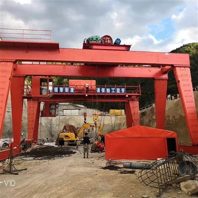
The 25T Rubber Tyred Gantry Crane is a fundamental piece of equipment for the horizontal transport and vertical stacking of containers in a port yard. Its unique combination of high lifting capacity, mobility, and high stacking capability makes it indispensable for efficient terminal operations, despite the ongoing challenges of automation and environmental impact.
Limitations and Considerations
Higher Operating Costs (Diesel RTGs): Significant fuel consumption and maintenance costs (engines, tires).
Tire Wear and Replacement: The massive tires are expensive and subject to wear and damage.
Emissions and Noise (Diesel RTGs): Produce local emissions and noise, whereas e-RTGs solve this problem.
Less Precision than RMGs: Can be affected by ground conditions and tire pressure.
Comparison: RTG vs. RMG
| Feature | RTG (Rubber-Tired Gantry) | RMG (Rail-Mounted Gantry) |
|---|---|---|
| Mobility | High - Rubber Tires | Low - Fixed Rails |
| Flexibility | Can move between yard blocks | Confined to one yard block |
| Infrastructure Cost | Lower (paved surface) | Higher (rails & foundation) |
| Operating Cost | Higher (fuel, tires) | Lower (electric power) |
| Precision & Stability | Good | Superior |
| Environmental Impact | Higher (Diesel) / Zero (e-RTG) | Zero (Electric) |
Conclusion: The Rubber Tyre Container Gantry Crane (RTG) is the workhorse of flexible container terminal operations. Its unique combination of mobility, high stacking capability, and versatility makes it the preferred choice for ports and yards that require adaptable container management. The industry's shift towards e-RTGs is addressing its traditional drawbacks of fuel cost and emissions, ensuring its continued relevance in modern, eco-conscious port operations.
Lifting Capacity 320 tons
Span (Width) 3 - 12 meters (adjustable)
Lifting Height 3 - 10 meters
Working Class A3-A5 (light to medium duty)
Hoisting Speed 0.5 - 8 m/min (variable)
Main Beam Type Single/double girder (box-type)
Power Supply 220V/380V 3-phase or manual
Control Mode Pendant control/wireless remote
Hoist Type Electric chain hoist/wire rope hoist
Travel Drive Manual push or motorized
Corrosion Protection Hot-dip galvanized or marine-grade paint
Wind Resistance Up to Beaufort scale 6 (for outdoor use)
Operating Temp -20°C to +50°C

Pictures & Components
1. Structural System (The Crane's Skeleton)
This is the main framework that supports all other components and withstands the loads.
Main Girder / Bridge Girder: The large, horizontal beam that spans the width of the container stacks. It travels along the length of the yard on the legs.
Legs: The vertical structures that support the main girder. RTGs typically have two legs at one end and one at the other to straddle a row of containers.
A-Frame / Rigid Legs: The two legs on one side are often connected by a diagonal brace, forming a rigid "A" structure for stability.
C-Frame / Cantilevered Leg: The single leg on the other side allows for easy truck traffic to pass underneath for picking up and dropping off containers.
End Trucks / Bogies: The assemblies at the bottom of each leg that house the wheels, tires, and drive motors. They are the "feet" of the crane.

2. Hoisting System (Lifts the Load)
This system is responsible for the primary function of lifting and lowering the container.
Trolley: The assembly that runs back and forth along the main girder, positioning the spreader laterally across the width of the container row.
Hoist Winch / Drum: The motor-driven drum located on the trolley around which the wire ropes are wound.
Wire Ropes / Hoist Ropes: High-strength steel cables that connect the hoist drum to the spreader.
Sheaves / Pulleys: Grooved wheels that guide the wire ropes, providing mechanical advantage and directing the path of the ropes.

Spreader: The device that physically locks onto the container. It's a complex component itself, often with:
Twistlocks: Hydraulically or mechanically operated pins that engage into the corner castings of a container.
Container Size Adjustment: Ability to telescopically adjust its length to handle 20ft, 40ft, 45ft, and sometimes even 48ft or 53ft containers.
Spreader Beam: The main structural member of the spreader.
3. Travel System (Moves the Crane)
This system allows the entire crane to move along the yard.
Tires / Wheels: Large, heavy-duty, pneumatic rubber tires (typically 8 or more). They are designed to carry immense loads.
Drive Motors: Electric motors (usually AC) that power the wheels. Each end truck will have several driven wheels.
Steering System: A critical system that allows all wheels to be steered, enabling the crane to:
90° Crabbing: Move diagonally across the yard.

Axis Steering: Move the crane in a straight line parallel to the container rows.
Tramming: Move the crane from one stack to another perpendicularly.
Braking System: Includes service brakes (for normal stopping) and parking/emergency brakes.

4. Power System (Provides Energy)
RTGs can be powered in several ways, but the 25T model is commonly diesel-electric.
Diesel Generator Set: A large diesel engine coupled with a generator to produce electricity for all the crane's functions (hoist, trolley, gantry travel). This makes the RTG self-powered and highly mobile.
Alternative Power Sources:

Electric RTG (e-RTG): Connects to the terminal's electrical grid via a cable reel, reducing noise and emissions.
Hybrid RTG: Uses a smaller diesel generator combined with a battery pack or supercapacitors to capture regenerative energy (from lowering loads/braking) and provide peak power, significantly saving fuel.
Power Distribution Panel / PCC (Power Control Center): Manages and distributes electrical power to all drives and auxiliary systems.
5. Control & Operator System (The Brain and Nerve Center)
This system allows the operator to control the crane safely and efficiently.
Operator's Cab: Located on the main girder, it provides the operator with a clear view of the spreader and container handling area. It is equipped with:

Master Switches / Joysticks: For precise control of hoisting, trolley travel, and gantry travel.
Control Panels & Displays: For monitoring crane functions, diagnostics, and spreader status.
Safety Devices: Emergency stop buttons, fire extinguisher, etc.
Programmable Logic Controller (PLC): The "brain" of the crane. It processes all operator commands and sensor inputs to control the motors and other devices.
Remote Control System: Many modern RTGs can be operated remotely from a control room in the terminal building, improving operator comfort and safety.

Safety & Protection Devices:
Anti-Collision Systems: Prevents collisions with other cranes and objects.
Container Stack Monitoring: Ensures safe stacking heights and stability.
Load Moment Indicator (LMI): Prevents overloads.
Anemometer: Measures wind speed and triggers alarms or shutdowns.
Anti-Sway System: Automatically reduces container swing.
Spread Lock Monitoring: Ensures twistlocks are properly engaged before lifting.

6. Safety & Auxiliary Systems (Protection and Support)
These are critical for safe and reliable operation.
Anti-Collision System: Uses sensors (laser, radar, or GPS) to prevent the crane from colliding with other cranes, stationary objects, or personnel.
Limit Switches: Prevent the trolley and hoist from moving beyond their safe physical limits.
Load Moment Indicator (LMI) / Rated Capacity Indicator (RCI): Monitors the load on the hoist and warns the operator if they are approaching or exceeding the crane's safe working limits.
Anemometer & Wind Speed Indicator: Measures wind speed and alarms or automatically stops crane operations if winds become dangerous.
Tire Pressure Monitoring System (TPMS): Continuously monitors the pressure in all tires to prevent damage and ensure stability.
Lighting & Warning Devices: Strobes, beacons, and horns to alert ground personnel when the crane is moving.
Fire Suppression System: Especially important in the engine room where the diesel generator is located.
Summary for a 25T RTG:
The "25T" specifically refers to its lifting capacity-it can lift 25 metric tonnes. All the components listed above are designed and scaled to handle this specific load, plus the weight of the spreader, within the specific span (e.g., stacking 1-over-5 or 1-over-6 containers wide) and height required by the container yard.

SKETCH

Main technical

Advantages
Advantages of Rubber Tyre Container Gantry Cranes
1. Superior Mobility and Flexibility
This is the defining advantage of RTGs over their rail-mounted counterparts (RMGs).
Rubber Tires: Unlike RMGs that are confined to fixed rails, RTGs run on rubber tires, allowing them to move freely across the terminal yard. They can easily transfer between different stacking blocks or work areas.
No Fixed Infrastructure: They do not require extensive and expensive fixed rail tracks to be installed across the yard. This makes them ideal for greenfield projects or for expanding existing terminals with minimal civil works.
Cross-Travel and Traversing: An RTG can move (or "traverse") sideways over a row of containers, as well as travel the length of the stacking block. This 2-dimensional movement is crucial for efficient container spotting.
2. High Space Utilization and Stacking Density
RTGs are designed to maximize the use of valuable terminal real estate.
Narrow Aisle Operation: They can operate in relatively tight spaces, typically requiring only a single lane for the crane itself and minimal space on either side for container clearance. This allows for dense stacking of containers.
High Stacking Capability: A standard 25T RTG can typically stack containers 1-over-5 or 1-over-6 high (meaning 5 or 6 containers high, plus one on the top of the stack), and across 6+ rows plus a truck lane. This vertical stacking dramatically increases a yard's storage capacity.
3. Operational Efficiency and Versatility
RTGs streamline the flow of containers between different modes of transport.
Direct Truck Interaction: They can directly load and unload trucks from the stack without requiring a secondary piece of equipment. The truck simply drives into the lane under the crane for a quick transfer.
Compatibility with Terminal Tractors: The workflow between an RTG and a terminal tractor (shuttle truck) is highly efficient, creating a continuous flow of containers to and from the quay crane.
Flexible Work Assignments: Because they are mobile, RTGs can be dynamically reassigned to different parts of the yard to handle peak loads, vessel work, or import/export areas as needed.
4. Cost-Effectiveness
For many terminals, RTGs offer a compelling financial advantage.
Lower Initial Infrastructure Cost: The absence of extensive rail networks and associated foundations significantly reduces the initial capital investment compared to an RMG system.
Scalability: It is easier and cheaper to expand a yard served by RTGs. You simply need to pave a new area and deploy an additional crane.
High Resale Value: RTGs are standardized, mobile assets that hold their value well and can be sold to other terminals if a terminal's needs change.
5. Modern Technological Enhancements
Today's RTGs are far more advanced and automated than their predecessors.
Auto-Steering/Guidance Systems: Using GPS, magnetic tags, or laser guidance, RTGs can drive themselves down stacking lanes with high precision, reducing driver fatigue and improving safety.
Container Position Verification: Automated systems (using spreader cameras or lasers) identify the exact location and skew of a container, allowing for semi- or fully-automatic landing.
Spreaders: They can be equipped with telescopic spreaders that handle 20ft, 40ft, and 45ft containers, and even twin-lift spreaders for moving two 20ft containers simultaneously, doubling productivity.
Electric and Hybrid Options: Modern RTGs often use diesel-electric generators or even hybrid systems with energy storage (batteries or supercapacitors) to capture regenerative energy from hoisting and lowering, leading to significant fuel savings and reduced emissions.
Application
Primary Applications
The 25T capacity makes it an extremely versatile workhorse in various material handling sectors. Its applications are broadly categorized as follows:
1. Port Container Terminals and Intermodal Yards
This is the most classic and widespread application.
Container Stacking: RTGs are used to create dense, high-capacity storage yards. They stack containers 1-over-4 or 1-over-5 high (meaning 4 or 5 containers on the ground, with one on top) and in multiple rows.
Transfer Operations: They move containers between the quay (where ship-to-shore cranes unload) and the storage yard, and then to trucks or trains for further transport.
Truck and Rail Loading/Unloading: RTGs efficiently service arriving and departing trucks and trains, picking up and dropping off containers directly onto the vehicle chassis or railcars.
2. Industrial and Manufacturing Plants
Factories with heavy raw materials or finished products extensively use 25T RTGs.
Steel Mills and Metal Fabrication: Handling coils of steel, sheets, and other heavy metal products.
Heavy Machinery Manufacturing: Moving large components like engines, turbines, and machine frames.
Logistics Warehouses for Heavy Goods: Managing the storage and movement of heavy items like large machinery, construction equipment, or pre-cast concrete elements.
3. Logistics and Freight Stations
Beyond major ports, smaller freight stations and logistics hubs use 25T RTGs to manage containerized cargo efficiently.
Consolidation and Deconsolidation: Sorting and organizing containers before they are sent to their final destination.
Temporary Storage: Providing a flexible storage solution without the need for permanent infrastructure.
4. Construction Projects
On large construction sites, especially for infrastructure projects.
Handling Pre-cast Concrete Elements: Lifting and placing large segments for bridges, tunnels, and buildings.
Positioning Heavy Materials: Moving steel beams, generators, and other heavy equipment to their required locations.
Crane production process
Phase 1: Design & Engineering
This is the foundational phase where the crane is conceived digitally.
Conceptual Design & Client Consultation: Engineers work with the client to determine key specifications:
Lifting Capacity: 25 Tons (and up to, for example, 40-50T under the spreader).
Span: The distance between the legs (e.g., 6+1 container rows wide).
Lifting Height: The height under the spreader (e.g., 1-over-5 or 1-over-6 containers high).
Power System: Diesel-electric, electric (with cable reel), or hybrid.
Control Systems: Cabin control, remote control, or both.
Detailed Engineering:
Structural Analysis: Using Finite Element Analysis (FEA) software to simulate stresses, deflections, and dynamic loads on the main girders, legs, and end carriages. This ensures structural integrity and compliance with international standards like FEM, ISO, or CMAA.
Mechanical Design: Detailed drawings for all mechanical components: hoist units, trolley, wheels, bogies, and steering systems.
Electrical & Control System Design: Schematics for the power distribution, motor drives, PLC (Programmable Logic Controller), safety systems, and communication networks.
Bill of Materials (BOM): A comprehensive list of all raw materials, purchased components, and standard parts is created.
Phase 2: Procurement & Sourcing
Raw Materials: High-strength steel plates (e.g., Q345B), profiles (I-beams, H-beams), and sheets are sourced.
Major Purchased Components: These are often sourced from specialized manufacturers:
Hoist & Trolley Assembly: The heart of the lifting system.
Motors & Drives: For hoisting, trolley travel, and gantry travel.
Electrics: PLC, variable frequency drives (VFDs), sensors, limit switches, cabling.
Power Pack: Diesel engine and generator set.
Wheels, Axles, and Bearings.
Operator's Cabin.
Phase 3: Fabrication & Manufacturing
This is the core physical production phase, primarily focused on the steel structure.
Steel Preparation:
Marking & Cutting: Steel plates are marked according to CAD drawings and cut using CNC plasma or flame cutting machines for precision.
Edge Preparation: Beveling edges for welding.
Sub-Assembly Fabrication:
Main Girder: The primary bridge beam is fabricated. Thick steel plates are welded into box-sections. Internal stiffeners and diaphragms are added to prevent buckling. This is a critical weld, often using submerged arc welding (SAW) for quality and penetration.
Legs & End Carriages: The supporting structures are built. They house the travel wheels, bogies, and steering mechanisms.
Trolley Frame: The frame that carries the hoist and travels along the main girder is fabricated.
Machining:
Critical mating surfaces, such as the rail running surfaces on the main girder and the connection points for legs, are machined on large boring mills or planers to ensure perfect flatness and alignment.
Phase 4: Assembly & Integration
The fabricated components and purchased parts are brought together.
Primary Structural Assembly (in the factory hall):
The main girder is placed on supports.
The legs and end carriages are bolted and/or welded to the main girder. This connection is crucial and heavily reinforced.
The entire structure is now recognizable as a gantry crane.
Mechanical System Installation:
The trolley rails are installed on the main girder.
The trolley is lifted onto the girder.
The hoist unit is installed on the trolley.
The gantry travel system (wheels, axles, gearboxes, motors) is assembled onto the end carriages.
Electrical System Installation:
Cable Trays & Conduits are installed along the main girder and down the legs.
Power and Control Cables are pulled through.
Motors, Drives, and the PLC Cabinet are installed and wired.
Safety Devices are installed: limit switches, anti-collision sensors, anemometers (wind sensors), and emergency stop buttons.
The operator's cabin is installed and connected.
Phase 5: Factory Acceptance Testing (FAT)
Before disassembly for shipment, the crane is tested at the factory to ensure it functions as designed.
Visual Inspection: Checking weld quality, paintwork, and assembly.
Dimensional Inspection: Verifying span, leg center distance, and other key dimensions.
Electrical Tests: Insulation resistance, continuity, and functional checks of all controls and safety devices.
No-Load Tests: Running all motions (hoist, trolley, gantry travel) without load to check for smooth operation, noise, and alignment.
Load Testing (The Critical Test):
Static Load Test: Lifting a test load 25-50% greater than the rated capacity (e.g., 31.25T for a 25T crane) and holding it to check for structural deflection and integrity.
Dynamic Load Test: Lifting the rated load (25T) and performing all operational functions to verify performance under real-world conditions.
The client or a third-party surveyor is often present to witness the FAT.
Phase 6: Dismantling, Painting & Shipping
Dismantling: The crane is carefully dismantled into major modules for transport:
Main Girder (often split into 2 or 3 sections)
Legs and End Carriages
Trolley
Electrical Panels
Cab
Surface Preparation & Painting:
Blasting: All steel surfaces are shot-blasted to SA 2.5 standard to remove rust and mill scale, creating a perfect surface profile for paint adhesion.
Painting: A multi-layer paint system is applied, typically an epoxy zinc-rich primer, an epoxy intermediate coat, and a polyurethane topcoat for weather and corrosion resistance. This is crucial for the crane's longevity in a harsh port environment.
Packaging & Shipping: Modules are securely packaged, protected, and loaded onto ships for transport to the client's port terminal.
Phase 7: Site Erection & Commissioning
Site Preparation: The client prepares the site, including a level, compacted gravel yard and installing the running rails.
Erection: Using mobile cranes, the manufacturer's erection team assembles the crane modules on-site.
Re-connection: All mechanical and electrical connections are re-established.
Site Acceptance Testing (SAT): A final round of testing is performed on-site to ensure the crane was reassembled correctly and operates perfectly in its final environment. This includes load testing, often with water-filled containers or calibrated weights.

Workshop view:
The company has installed an intelligent equipment management platform, and has installed 310 sets (sets) of handling and welding robots. After the completion of the plan, there will be more than 500 sets (sets), and the equipment networking rate will reach 95%. 32 welding lines have been put into use, 50 are planned to be installed, and the automation rate of the entire product line has reached 85%.


Hot Tags: 25t rubber tyre container gantry crane, China 25t rubber tyre container gantry crane manufacturers, suppliers, factory
You Might Also Like


Send Inquiry