


Rtg Tyre Container Gantry Crane
Products Description
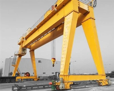
What is an RTG Tyre Container Gantry Crane?
An RTG (Rubber-Tired Gantry) Tyre Container Gantry Crane is a massive, self-propelled, mobile gantry crane used in port terminals, intermodal yards, and logistics hubs for stacking and moving shipping containers. Its defining feature is its use of rubber tires, which give it the freedom to travel anywhere within the container yard, unlike its rail-bound counterpart, the RMG (Rail-Mounted Gantry).
Think of it as a highly mobile, container-stacking giant that can drive from one stack to another, providing unparalleled flexibility in container yard management.
Advantages of RTG Tyre Container Gantry Cranes
High Mobility and Flexibility: Can be driven anywhere in the container yard, allowing for flexible stack organization and easy relocation between yard blocks.
High Stacking Density: Can stack containers 5-6 high and 6+ containers wide, maximizing yard space utilization.
Rapid Transfer Operations: Ideal for quickly moving containers between stacks, trucks, and railcars.
No Fixed Infrastructure Required: Unlike RMGs, they do not require expensive, fixed rail tracks, offering a lower initial infrastructure cost.
Adaptability: Easily integrated into existing terminals and can be used in various yard layouts.
Comparison: RTG vs. RMG
| Feature | RTG (Rubber-Tired Gantry) | RMG (Rail-Mounted Gantry) |
|---|---|---|
| Mobility | High - Rubber Tires | Low - Fixed Rails |
| Flexibility | Can move between yard blocks | Confined to one yard block |
| Infrastructure Cost | Lower (paved surface) | Higher (rails & foundation) |
| Operating Cost | Higher (fuel, tires) | Lower (electric power) |
| Precision & Stability | Good | Superior |
| Environmental Impact | Higher (Diesel) / Zero (e-RTG) | Zero (Electric) |
Conclusion: The RTG Tyre Container Gantry Crane is the workhorse of flexible container terminal operations. Its unique combination of mobility, high stacking capability, and versatility makes it the preferred choice for ports and yards that require adaptable container management. The industry's shift towards e-RTGs is addressing its traditional drawbacks of fuel cost and emissions, ensuring its continued relevance in modern, eco-conscious port operations.
Lifting Capacity 320 tons
Span (Width) 3 - 12 meters (adjustable)
Lifting Height 3 - 10 meters
Working Class A3-A5 (light to medium duty)
Hoisting Speed 0.5 - 8 m/min (variable)
Main Beam Type Single/double girder (box-type)
Power Supply 220V/380V 3-phase or manual
Control Mode Pendant control/wireless remote
Hoist Type Electric chain hoist/wire rope hoist
Travel Drive Manual push or motorized
Corrosion Protection Hot-dip galvanized or marine-grade paint
Wind Resistance Up to Beaufort scale 6 (for outdoor use)
Operating Temp -20°C to +50°C

Pictures & Components
Here is a detailed breakdown of the components of an RTG Tyre Container Gantry Crane.
1. Primary Structural System (The Skeleton)
Portal Frame & Legs: The massive steel framework that forms the main structure straddling the container stacks. Typically consists of 4-8 legs depending on the span and capacity. Designed to withstand heavy dynamic loads.
Lifting Girder / Boom: The primary horizontal beam(s) that connect the legs and provide the track for the trolley to travel across the width of the container rows.
Rubber Tires & Suspension:
Tires: Typically 8 or 16 massive, heavy-duty pneumatic tires. The multi-wheel configuration helps distribute the extreme weight of the crane and load.
Suspension System: Hydraulic or mechanical system that ensures all wheels maintain ground contact and helps stabilize the crane on uneven ground.

2. Container Handling System (The Workhorse)
Spreader: The intelligent container-lifting device.
Telescopic Mechanism: Adjusts length to handle 20ft, 40ft, and 45ft containers.
Twistlocks: Rotating conical locks that engage the container's corner castings.
Weighing System: Integrated load cells for weighing containers during handling.

Hoist System:
Hoist Motors: High-torque electric motors for main and auxiliary lifting.
Wire Rope Drums: Large drums that spool the hoist wires.
Wire Ropes: High-strength steel cables for lifting containers.
Trolley Assembly:
Trolley Frame: Steel structure that carries the hoist machinery.
Trolley Wheels & Drive: Flanged wheels and drive motors that run on rails on the boom.
Rope Sheaves: Pulleys that guide the wire ropes from the hoist to the spreader.

3. Power & Drive Systems (The Muscles)
Power Generation System:
Diesel Engine: A large, high-horsepower diesel engine (typically 500-1000 kW).
Generator: Converts engine power to electrical power.
Alternatives: Newer models may be e-RTGs (Electric RTGs) that draw power from a central grid or use hybrid diesel-electric systems.
Travel Drives:
Drive Motors: Electric motors at each wheel or axle for propulsion.
Gearboxes & Wheels: Transmit power to the tires.

Steering System:
Hydraulic Steering Actuators: Provide power for wheel turning.
Control Modes: Allows for coordinated all-wheel steering, including:
90-degree steering (crab steering)
Articulated steering
Diagonal steering
Trolley & Hoist Drives: Separate electric motor systems for cross-traverse and lifting motions.

4. Control & Safety Systems (The Brain & Nerves)
Operator Control Systems:
Operator's Cab: An elevated, climate-controlled cabin mounted on the portal frame, giving the operator a panoramic view of the spreader and container stacks.
Control Consoles: Joysticks, switches, and screens for controlling all crane functions.
Automation & Sensing Systems:
Container Position Automation: Automatically positions the spreader over the target container.
Optical Character Recognition (OCR): Cameras that automatically read container numbers.
Laser Scanning & GPS: For precise container positioning and stack measurement.

Safety & Protection Devices:
Anti-Collision Systems: Prevents collisions with other cranes and objects.
Container Stack Monitoring: Ensures safe stacking heights and stability.
Load Moment Indicator (LMI): Prevents overloads.
Anemometer: Measures wind speed and triggers alarms or shutdowns.
Anti-Sway System: Automatically reduces container swing.
Spread Lock Monitoring: Ensures twistlocks are properly engaged before lifting.

5. Auxiliary Systems
Lighting: High-intensity lights for night operations.
Fire Protection: Fire detection and suppression systems.
Communication: Intercom and radio systems.
Monitoring & Diagnostics: Continuous monitoring of crane systems with remote diagnostics capability.
Tire Pressure Monitoring System (TPMS): Critical for maintaining stability and preventing tire damage.

SKETCH

Main technical

Advantages
Advantages of RTG Tyre Container Gantry Cranes
RTG Cranes offer a unique set of benefits that make them indispensable in modern container terminal operations.
1. Unmatched Mobility and Flexibility
Free-Roaming Capability: Unlike rail-mounted cranes, RTGs can drive anywhere within the terminal, allowing operators to easily reposition them between different yard blocks as workload demands change.
Adaptable Operations: This mobility provides terminal operators with the flexibility to reorganize storage layouts, respond to changing vessel schedules, and manage peak workloads efficiently.
2. High Stacking Density
Space Optimization: RTGs can typically stack containers 5 high and 6 to 8 containers wide under a single crane span, maximizing the utilization of valuable yard space.
High Yard Capacity: This dense stacking capability allows terminals to store a large number of containers in a relatively compact area.
3. Rapid Operational Deployment
Quick Truck Servicing: RTGs are excellent for quickly loading and unloading trucks, as they can be driven directly to the required container stack without complex scheduling.
Fast Container Transfers: They enable efficient reshuffling of containers within the yard and rapid movement between storage areas.
4. Infrastructure Versatility
Lower Initial Infrastructure Cost: RTGs require only a paved surface to operate, which is significantly less expensive than installing the reinforced concrete foundations and rails required for RMGs.
Easier Yard Expansion: Adding more RTGs or expanding the storage yard is generally simpler and more cost-effective than expanding fixed rail systems.
5. Advanced Technology Integration
Automation Ready: Modern RTGs are often equipped with features like automatic stacking, optical character recognition, and GPS guidance, which can lead towards semi- or full-automation.
Comprehensive Safety Systems: Include spreader lock monitoring, anti-collision systems, and load moment indicators, creating a safer work environment.
Application
Applications of RTG Tyre Container Gantry Cranes
RTG Cranes are specialized for specific, high-volume container handling scenarios.
1. Container Ports and Terminals (Primary Application)
Yard Stacking Operations: This is the core application. RTGs are used for storing containers in the yard, moving them between stacks, and organizing them based on vessel, destination, or priority.
Truck Handling: Servicing import and export trucks by quickly retrieving containers from storage or placing containers into storage.
Vessel Support: Working in conjunction with quay cranes, RTGs transport containers to and from the quayside for loading onto and unloading from ships.
2. Intermodal Rail Yards
Train Loading/Unloading: Transferring containers directly between railcars and the storage yard.
Rail Yard Sorting: Organizing containers within the rail yard based on their destination or train schedule.
3. Inland Container Depots (ICDs) and Logistics Hubs
Long-Term Storage: Providing flexible and dense storage for containers away from the main port area.
Cargo Consolidation: Handling containers in facilities where goods are packed or unpacked, requiring frequent movement and reorganization of containers.
Crane production process
The production process for an RTG Tyre Container Gantry Crane is a complex, multi-stage procedure that involves advanced engineering, heavy fabrication, precision assembly, and rigorous testing. Here is a detailed breakdown.
Stage 1: Design & Engineering
This is the foundational stage where the crane's performance and safety are defined.
Client & Terminal Specification Analysis: Reviewing requirements: stacking capacity (e.g., 1-over-5 or 1-over-6), span (e.g., 7+1 or 8+1), lifting capacity (typically 40-50 tons under spreader), and operational needs (diesel-electric, e-RTG, automation level).
Advanced Engineering:
Structural Analysis (FEA): Using Finite Element Analysis to model the entire portal structure, legs, and boom under dynamic loads, including wind, seismic, and collision scenarios.
Mechanical Design: Designing the high-speed hoist machinery, trolley, complex steering system, and travel drives.
Electrical & Control Design: Creating schematics for the power generation system (or e-RTG power intake), motor drives (VFDs), PLC networks, and the integration of all automation systems (OCR, GPS, auto-steering).
Bill of Materials (BOM) Creation: A comprehensive list of all raw materials and thousands of purchased components.
Stage 2: Material Procurement & Preparation
Procurement: Sourcing certified high-tensile steel plates and sections. Ordering specialized components from global suppliers: Caterpillar/Cummins engines, Siemens/ABB motors and drives, R&M spreaders, etc.
Material Preparation: Steel plates are shot-blasted and primed. They are then cut to size using massive CNC plasma or flame cutting machines for precision.
Stage 3. Structural Fabrication & Assembly
This is where the crane's massive skeleton is built.
Panel and Sub-Assembly Fabrication:
Leg & Boom Sections: The legs and boom are fabricated as large box girders from steel plate. Internal stiffeners are welded in to prevent buckling.
Process: Components are fit in massive, custom jigs. Critical welds are performed using Automated Submerged Arc Welding (SAW). All critical welds are inspected via Ultrasound (UT) or X-ray (RT).
Stress Relieving: The completed major sections (legs, boom segments) are heated in a computer-controlled furnace to relieve internal stresses from welding, preventing future distortion.
Machining: Connection points, rail mounting surfaces, and drive mounting pads are machined to ensure perfect alignment.
Stage 4: Mechanical Assembly
The structural frame is integrated with the mechanical systems.
Mega-Blocks Assembly: Large sub-sections, like a full leg with its steering and drive assembly, are pre-assembled.
Portal Frame Assembly: The main boom sections are joined to the legs to form the complete portal structure.
Drive & Steering Unit Installation: The travel drive assemblies (motor, gearbox, wheel) and the complex hydraulic steering actuators are installed.
Hoist and Spreader Assembly: The high-speed hoist units are mounted onto the trolley. The spreader is assembled and tested separately.
Stage 5: Electrical & Control System Installation
The crane's "nervous system" is installed.
Power System Installation:
For Diesel-Electric: The large diesel engine and generator set are installed and aligned.
For e-RTG: The cable reel or conductor bar system is installed.
Cable Installation: Kilometers of power and control cables are laid in protective cable trays.
Panel Installation: Main switchboards, VFD drive cabinets, and PLC control panels are installed.
Sensor and Automation System Installation: GPS antennas, OCR cameras, laser scanners, and anti-collision sensors are mounted and wired.
Operator Cab Installation: The elevated, climate-controlled cab is installed with all control consoles.
Stage 6: Pre-Delivery Testing & Inspection (FAT)
Before disassembly, the fully erected crane undergoes rigorous testing.
Visual & Dimensional Inspection: Verifying workmanship and all critical dimensions.
No-Load Test: Running all motions (hoist, trolley, gantry travel, steering) without a load.
Load Testing:
Static Load Test: Lifting a test load of 125% of the rated capacity.
Dynamic Load Test: Lifting 110% of the rated capacity and running it through all motions.
Functionality & Safety Tests: Verifying all limit switches, E-stops, overload protection, steering modes, and automated systems.
Stage 7: Dismantling, Painting & Shipment
Systematic Dismantling: The crane is carefully disassembled into transportable modules (leg sections, boom segments, trolley, spreader).
Final Painting: A high-performance, multi-coat paint system is applied for corrosion protection in harsh saltwater environments.
Packaging & Shipment: Components are securely packaged and shipped via heavy-lift vessels to the client's port.
Stage 8: Site Erection & Commissioning (SAT)
Site Preparation: The terminal's paved area is verified for suitability.
Erection: Using large mobile cranes, the manufacturer's specialized crew reassembles the RTG on-site.
Final Connections & Testing: All systems are re-connected and subjected to a final Site Acceptance Test (SAT).
Operator Training: Comprehensive training is provided for the terminal's personnel.

Workshop view:
The company has installed an intelligent equipment management platform, and has installed 310 sets (sets) of handling and welding robots. After the completion of the plan, there will be more than 500 sets (sets), and the equipment networking rate will reach 95%. 32 welding lines have been put into use, 50 are planned to be installed, and the automation rate of the entire product line has reached 85%.


Hot Tags: rtg tyre container gantry crane, China rtg tyre container gantry crane manufacturers, suppliers, factory
You Might Also Like


Send Inquiry